EP1106426A2 - Rotatable headrest - Google Patents
Rotatable headrest Download PDFInfo
- Publication number
- EP1106426A2 EP1106426A2 EP00126116A EP00126116A EP1106426A2 EP 1106426 A2 EP1106426 A2 EP 1106426A2 EP 00126116 A EP00126116 A EP 00126116A EP 00126116 A EP00126116 A EP 00126116A EP 1106426 A2 EP1106426 A2 EP 1106426A2
- Authority
- EP
- European Patent Office
- Prior art keywords
- portions
- stay
- headrest
- frame body
- connecting portion
- Prior art date
- Legal status (The legal status is an assumption and is not a legal conclusion. Google has not performed a legal analysis and makes no representation as to the accuracy of the status listed.)
- Granted
Links
- 230000002093 peripheral effect Effects 0.000 claims description 6
- 238000005452 bending Methods 0.000 claims 1
- 238000005187 foaming Methods 0.000 abstract description 11
- 239000011347 resin Substances 0.000 abstract description 10
- 229920005989 resin Polymers 0.000 abstract description 10
- 238000000465 moulding Methods 0.000 abstract description 4
- 238000010097 foam moulding Methods 0.000 description 5
- 239000011324 bead Substances 0.000 description 3
- 238000003466 welding Methods 0.000 description 3
- 239000002184 metal Substances 0.000 description 2
- 238000000034 method Methods 0.000 description 2
- 230000008878 coupling Effects 0.000 description 1
- 238000010168 coupling process Methods 0.000 description 1
- 238000005859 coupling reaction Methods 0.000 description 1
- 230000001105 regulatory effect Effects 0.000 description 1
- 239000007787 solid Substances 0.000 description 1
Images



Classifications
-
- B—PERFORMING OPERATIONS; TRANSPORTING
- B60—VEHICLES IN GENERAL
- B60N—SEATS SPECIALLY ADAPTED FOR VEHICLES; VEHICLE PASSENGER ACCOMMODATION NOT OTHERWISE PROVIDED FOR
- B60N2/00—Seats specially adapted for vehicles; Arrangement or mounting of seats in vehicles
- B60N2/80—Head-rests
- B60N2/806—Head-rests movable or adjustable
- B60N2/838—Tiltable
- B60N2/841—Tiltable characterised by their locking devices
- B60N2/847—Tiltable characterised by their locking devices with stepwise positioning
Definitions
- the present invention relates to a headrest device having a headrest frame body and a stay, which is used in an automobile seat, and more particularly to a headrest device of which the headrest frame body covers a pair of leg member portions of the stay.
- a headrest device used in an automobile seat includes, an inverse U-shaped stay having opposing leg member portions which are held by a seat back frame of a vehicle and a connecting portion which connects the leg member portions, and a headrest frame body which supports a headrest pad made of foaming resin.
- the headrest frame body is extended to a position above the connecting portion of the stay.
- the connecting portion and the headrest frame body are connected by using brackets or by way of bushings such that a portion of the headrest frame body is curled on the connecting portion.
- the leg member portions of the stay become an exposed state to the headrest frame body. Accordingly, the rotational movement of the headrest in the back and forth direction becomes difficult due to the integrated foam molding of the headrest pad.
- a headrest frame body adopts an overlapped structure made of two sheets of pressed members or a structure made of a single sheet of plate-like pressed member by a press-molded process, wherein the press-molded member cover leg member portions of a stay and a restricting portion which enables the tilting or the movement of the headrest in the back and forth direction is provided.
- the tilting of the headrest in the back and forth direction becomes easy and there is no possibility that the tilting of the headrest which has an integral structure made of a headrest pad and a headrest frame body by a foam molding is hampered by the headrest pad.
- the present invention provides a headrest device including an inverse U-shaped stay having opposing leg member portions held by a seat back frame of a vehicle and a connecting portion which connects the leg member portions, and a headrest frame body which is supported on the stay such that the headrest frame body is rotatable in the back and forth direction about the connecting portion of the stay, wherein the headrest frame body is comprised of a pair of opposing plate bodies, each plate body comprises a support portion of an approximately semicircular cross section which has a portion coming into contact with the connecting portion of the stay and restricting portions of an approximately U-shaped cross section which cover the leg member portions of the stay and restrict the rotation of the headrest frame body about the connecting portion of the stay, and both plate bodies have a relationship where both plates have support portions and restricting portions thereof opposed and fixedly secured to each other.
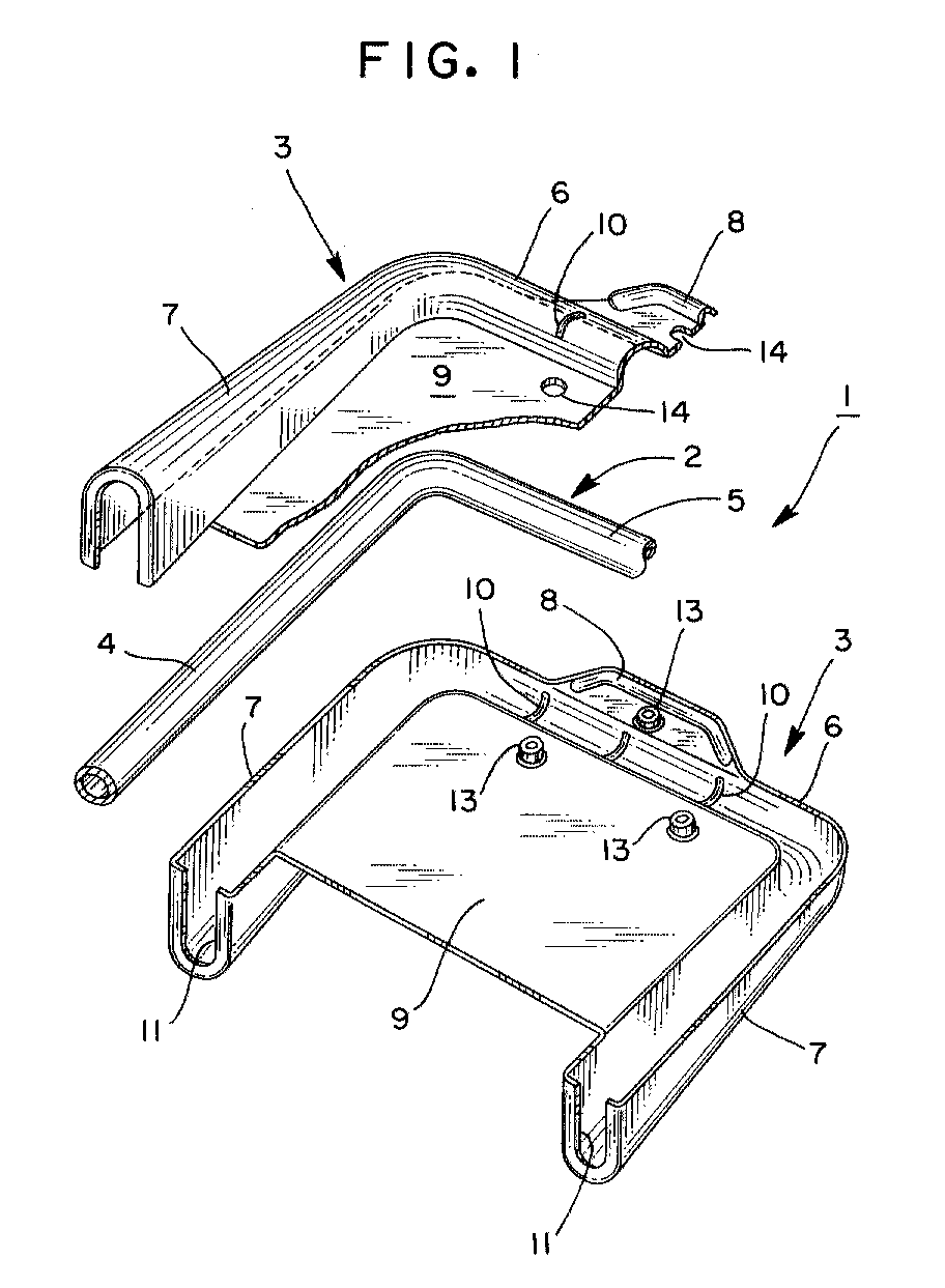
- Fig. 1 is a perspective view with a part cut away of a headrest device of an embodiment of the present invention.
- Fig. 2 is a side view of the headrest device of the embodiment shown in Fig. 1 in the assembled state.
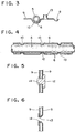
- Fig. 3 is a partial cross-sectional view showing a bead portion.
- Fig. 4 is a cross-sectional view of a friction holding portion defined between a stay and a headrest frame body.
- Fig. 5 is a cross-sectional view showing a pin caulking.
- Fig. 6 is a cross-sectional view showing a burring caulking.
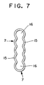
- Fig. 7 is a bottom view showing an inner space of a restricting portion.
- Fig. 8 is a partial perspective view showing another embodiment of the present invention.
- a headrest device 1 is comprised of an inverted U-shaped stay 2 and a pair of plate bodies 3, 3.
- the stay 2 is constituted by opposing leg member portions 4 which are held by a seat back frame of a vehicle not shown in the drawing and a connecting portion 5 which connects both leg member portions 4.
- the stay 2 is made of a pipelike or solid rod having a circular cross section.
- Each plate body 3 is formed by pressing a metal sheet and is comprised of a support portion 6 which has an approximately semicircular cross section and covers the connecting portion 5 of the stay 2 and restricting portions 7, 7 which each has an approximately U-shaped cross section and a triangular side surface (in side view) having a wider width at its free end and covers each of the leg member portions 4 of the stay 2.
- the plate body 3 has a bead portion 8 (see Fig. 3) designated by the laws and regulations.
- a planar portion 9 is formed between both restricting portions 7, 7.
- a plurality of protruding portions 10 which bulge inwardly are formed on an inner peripheral surface of the support portion 6. These protruding portions 10 are brought into friction contact with an outer peripheral surface of the connecting portion 5 of the stay 2 thus providing a frictional movement of the headrest (see Fig. 4).
- Flange portions 11 which are directed inwardly are formed on free end peripheries of the restricting portions 7, 7.
- Respective plate bodies 3, 3 are arranged in the left-and-right (or front-and-rear) symmetry and have the equal shape. Both plate bodies 3, 3 are jointed such that both plates bodies 3, 3 are coupled by performing a pin caulking using pins 12 as shown in Fig. 5 or by forming burring 13 on one planer portion 9 and performing a burring caulking through a hole 14 formed on the other planer portion 9 as shown in Fig. 6.
- the coupled plate bodies 3, 3 constitute a headrest frame body.
- the caulking position may be arranged at three positions as shown in Fig. 1, wherein the caulking is performed at two left-and-right symmetrical positions at an upper portion of the planar portion 9 and the caulking is performed on a center line of the planar portion 9 disposed between the bead portion 8 and the support portion 6.
- portions of respective plate bodies 3, 3 may be brought into contact with each other and are adhered to each other by a spot welding.
- the relative movement between the headrest frame body constituted by the plate bodies 3, 3 and the stay 2 is restricted by bringing the flange portions 11 into contact with the leg member portions 4 of the stay 2. Further, the headrest frame body constituted by the plate bodies 3, 3 can maintain its position by the frictional engagement between the support portions 6 of the plate bodies 3, 3 and the connecting portion 5 of the stay 2.
- a headrest pad (indicated by a chain line in Fig. 2) made of foaming resin is integrally formed with the headrest frame body constituted by the plate bodies 3, 3 by a foam molding.
- the flange portions 11 can prevent the wraparound of the foaming resin into the inside of the restricting portions 7 or can prevent the wraparound of the foaming resin between both opposing planar portions 9 thereby the integrated foam molding of the headrest can be facilitated.
- the inner wall surface which defines a space portion 16 of the restricting portion 7 may have a corrugated shape 15 as shown in Fig. 7.
- the corrugated shape 15 is formed by contiguously connecting arcuate surfaces having a diameter corresponding to a diameter of the leg member portion 4 of the stay 2.
- the headrest frame body constituted by the plate bodies 3, 3 When it is necessary to change the relative position of the headrest frame body constituted by the plate bodies 3, 3 with respect to the stay 2, the headrest frame body constituted by the plate bodies 3, 3 is pushed in a given direction such that the leg member portion 4 of the stay 2 gets over a small ridge formed between contiguous arcuate surfaces.
- an insert having the corrugated form 15 may be prepared as a separate member and may be inserted into the space portion 16 of the restricting portion 7.
- a headrest frame body is produced by forming a pair of frame portions 20 by molding a sheet of metal plate with a press.
- a pair of frame portions 20 have the equal shape and respective frame portions 20 are arranged in the left-and-right (or front-and-rear) symmetry.
- Each frame portion 20 which constitutes the headrest frame body includes an upper groove portion 21, side groove portions 22 and a lower groove portion 23 at a side peripheral portion thereof.
- the upper groove portion 21 has a semicircular cross section to receive a connecting portion 5 of an inverse U-shaped stay 2.
- Cutout grooves 25 are formed in the upper groove portion 21 at two portions, preferably, at left and right portions thereof and the upper groove portion 21 extending between the cutout grooves 25 are brought into friction contact with the connecting portion 5 of the stay 2 so as to apply resistance to the tilting of the headrest frame body constituted by the frame portions 20, 20 about the connecting portion 5.
- the cutout grooves 25 contributes to the adjustment of the friction force between the stay 2 and the connecting portion 5.
- the side groove portions 22 have a shape for receiving leg member portions, that is, leg portions 4 of the stay 2.
- the side groove portions 22 preferably increases the depth of the groove as the side groove portions 22 move in the downward direction such that the side groove portions 22 have a triangular shape when viewed from both sides thereof.
- the lower groove portion 23 has a shape suitable for ensuring the rigidity of the frame bodies 20, 20 and is provided with opening portions 26 for allowing the leg portions 4 of the stay 2 to pass therethrough at a lower surface portion thereof. These opening portions 26 restrict the tilting of the headrest frame body to the stay 2.
- the flat planer portions 24 of respective frame portions 20, 20 may be brought into contact with each other at the spot welding portions and remaining portions may be spaced apart from each other in an opposed manner. In this case, an amount of distance between the remaining portions is increased as it moves downwardly.
- a headrest device ensures the movement of a headrest frame body to a stay and enables a foaming resin molding of a headrest.
- a support portion having a semicircular cross section and restricting portions having an approximately U-shape cross section are formed on aplate body. Two sheets of plate bodies are connected with each other in an opposed manner. Then, a headrest pad made of foaming resin is integrally formed with the plate bodies.
Landscapes
- Engineering & Computer Science (AREA)
- Aviation & Aerospace Engineering (AREA)
- Transportation (AREA)
- Mechanical Engineering (AREA)
- Chair Legs, Seat Parts, And Backrests (AREA)
- Seats For Vehicles (AREA)
Abstract
Description
Claims (9)
- A headrest device including an inverted U-shaped stay having opposing leg member portions adapted to be held by a seat back frame of a vehicle and a connecting portion which connects the leg member portions, and a headrest frame body which is supported on the stay such that the headrest frame body is rotatable in the back and forth directions about the connecting portion of the stay,
wherein the headrest frame body is comprised of a pair of opposing plate bodies, which each comprises a support portion of an approximately semicircular cross section which has a portion coming into contact with the connecting portion of the stay and restricting portions which cover the leg member portions of the stay and restrict the rotation of the headrest frame body about the connecting portion of the stay, both plate bodies having a relationship where both plates have support portions and restricting portions thereof opposed to each other and fixedly secured to each other. - A headrest device according to claim 1, wherein the restricting portions of the plate bodies have an approximately U-shaped cross section and triangular side surfaces which have a wider width at free ends thereof and peripheral portions of the free ends have flange portions bent inwardly.
- A headrest device according to claim 1, wherein inner peripheral surfaces of the support portions of the plate bodies have protruding portions which are bulged inwardly and the protruding portions are brought into contact with an outer peripheral surface of the connecting portion of the stay.
- A headrest device according to claim 2, wherein the plate bodies have planar portions between both restricting portions and both planar portions which oppose each other are joined by caulking.
- A headrest device according to claim 4, wherein a pair of plate bodies has the equal shape.
- A headrest device according to claim 2, wherein inner wall surfaces which define inner space portions of the restricting portions have a corrugated shape.
- A headrest device including an inverted U-shaped stay adapted to be held by a top portion of a seat back, a headrest frame body having an upper end portion thereof rotatably supported in the back and forth directions on a connecting portion which connects upper end portions of left and right leg portions of the stay, and a headrest pad which surrounds the headrest frame body and forms a head rest body together with the headrest frame body, wherein the headrest body is rotatable in the back and forth direction about the connecting portion of the stay which works as the center of rotation, the headrest frame body being constituted by making a pair of front and rear plate-like frame portions which are integrally connected at upper end portions thereof oppose and join each other, fitting grooves having an approximately semicircular cross section and into which an upper portion of the stay is fitted being provided between both frame portions, a pair of left and right side restricting portions which are extended downwardly from respective left and right ends of the fitting grooves and into which respective left and right leg portions of the stay are fitted and through which respective left and right leg portions pass downwardly, the fitting grooves being formed into a shape which applies a given rotational friction force to the connecting portion of the stay being in the state that the stay is accommodated in the fitting grooves, and each side restricting portions being formed into a shape which allows the rotation of a given amount of the headrest frame body in the back and forth direction about the connecting portion of the stay.
- A headrest device according to claim 7, wherein the stay is formed by bending a column-like rod in an approximately U-shape, the fitting grooves of the headrest frame body being formed into a circular cross section corresponding to the connecting portion of the stay, and each side restricting portions of the headrest frame body being formed into a shape which gradually increases a back-and-forth width thereof in the downward direction.
- A headrest device according to claim 7, wherein cutout portions are formed in the frame portions such that the cutout portions are formed at both sides of the fitting grooves.
Applications Claiming Priority (2)
| Application Number | Priority Date | Filing Date | Title |
|---|---|---|---|
| JP33979099A JP4272319B2 (en) | 1999-11-30 | 1999-11-30 | Headrest device |
| JP33979099 | 1999-11-30 |
Publications (3)
| Publication Number | Publication Date |
|---|---|
| EP1106426A2 true EP1106426A2 (en) | 2001-06-13 |
| EP1106426A3 EP1106426A3 (en) | 2003-09-10 |
| EP1106426B1 EP1106426B1 (en) | 2008-01-02 |
Family
ID=18330840
Family Applications (1)
| Application Number | Title | Priority Date | Filing Date |
|---|---|---|---|
| EP00126116A Expired - Lifetime EP1106426B1 (en) | 1999-11-30 | 2000-11-29 | Rotatable headrest |
Country Status (4)
| Country | Link |
|---|---|
| US (1) | US6412872B2 (en) |
| EP (1) | EP1106426B1 (en) |
| JP (1) | JP4272319B2 (en) |
| DE (1) | DE60037633T2 (en) |
Cited By (3)
| Publication number | Priority date | Publication date | Assignee | Title |
|---|---|---|---|---|
| FR2804387A1 (en) * | 2000-01-28 | 2001-08-03 | Aisin Seiki | HEADSET APPARATUS FOR VEHICLE SEAT |
| FR2947777A1 (en) * | 2009-07-09 | 2011-01-14 | Faurecia Sieges D Automobiles | Tiltable headrest for use on seat of vehicle, has clamp comprising curved bottom portion with preformed plane faces that are circumferentially distributed on bottom portion of clamp and extend parallel to rotation axis |
| FR3003211A1 (en) * | 2013-03-18 | 2014-09-19 | Cera | HEADREST FOR THE SEAT OF A MOTOR VEHICLE |
Families Citing this family (32)
| Publication number | Priority date | Publication date | Assignee | Title |
|---|---|---|---|---|
| JP4465782B2 (en) | 2000-02-29 | 2010-05-19 | アイシン精機株式会社 | Headrest device |
| US20050127734A1 (en) * | 2003-12-16 | 2005-06-16 | Lear Corporation | Energy management head restraint insert |
| US7537282B2 (en) * | 2003-12-16 | 2009-05-26 | Lear Corporation | Head restraint arrangement for a vehicle seat and a method of manufacture |
| USD536566S1 (en) * | 2004-04-28 | 2007-02-13 | Burch S Arthur | School bus seat back envelope cushion |
| US7740322B2 (en) * | 2004-09-30 | 2010-06-22 | Selwyn Arthur Burch | School bus seat with energy absorber |
| US7338119B2 (en) | 2004-09-30 | 2008-03-04 | Selwyn Arthur Burch | School bus seat with energy absorber |
| US8647544B2 (en) * | 2004-09-30 | 2014-02-11 | Selwyn Arthur Burch | Method for manufacturing school bus seat with energy absorber and using same |
| DE102005015292B3 (en) * | 2005-04-01 | 2006-11-30 | Johnson Controls Gmbh | Headrest for a vehicle, method for making a headrest and vehicle seat |
| JP2008253333A (en) * | 2007-03-31 | 2008-10-23 | T S Tec Kk | Headrest and vehicle seat equipped with this headrest |
| JP5059485B2 (en) * | 2007-05-25 | 2012-10-24 | 有限会社オダ技商 | Headrest device |
| US20090167069A1 (en) * | 2007-12-28 | 2009-07-02 | Tachi-S Co., Ltd. | Inclinable headrest |
| KR200451797Y1 (en) | 2008-06-13 | 2011-01-12 | 정해일 | Headrest Angle Adjustment |
| JP5428308B2 (en) * | 2008-11-28 | 2014-02-26 | 東海化成工業株式会社 | Headrest device |
| US7931331B2 (en) * | 2009-03-26 | 2011-04-26 | Faurecia Automotive Seating, Inc. | Headrest with energy dissipater for rear passenger |
| US8322790B2 (en) * | 2009-04-08 | 2012-12-04 | Lear Corporation | Seat assembly having a multi-position head restraint assembly |
| US8163704B2 (en) * | 2009-10-20 | 2012-04-24 | Novartis Ag | Glycoside derivatives and uses thereof |
| JP5685026B2 (en) * | 2010-07-30 | 2015-03-18 | 日本テクニカ株式会社 | Headrest bracket support structure |
| DE102012012684B3 (en) * | 2012-06-27 | 2013-11-21 | Johnson Controls Gmbh | FASTENING ARRANGEMENT, HEADREST AND ASSEMBLY PROCEDURE |
| USD699959S1 (en) | 2012-09-20 | 2014-02-25 | Steelcase Inc. | Chair |
| USD781605S1 (en) | 2015-04-24 | 2017-03-21 | Steelcase Inc. | Chair |
| DE102013208316B3 (en) * | 2013-05-07 | 2014-05-15 | Lear Corp. | Headrest for use with vehicle seat, has socket element formed with recess to secure headrest components together, where headrest components are disengaged from socket element by loosening plug element |
| US9174559B2 (en) * | 2013-07-16 | 2015-11-03 | Bose Corporation | Headrest |
| WO2015195653A1 (en) * | 2014-06-16 | 2015-12-23 | Zodiac Seats Us Llc | Lightweight headrests with suspension mesh and supporting frame |
| USD760526S1 (en) | 2015-04-24 | 2016-07-05 | Steelcase Inc. | Headrest assembly |
| USD781604S1 (en) | 2015-04-24 | 2017-03-21 | Steelcase Inc. | Chair |
| USD759415S1 (en) | 2015-04-24 | 2016-06-21 | Steelcase Inc. | Headrest |
| USD758774S1 (en) | 2015-04-24 | 2016-06-14 | Steelcase Inc. | Headrest assembly |
| US12337742B2 (en) * | 2020-08-31 | 2025-06-24 | Ts Tech Co., Ltd. | Headrest for a passenger seat of a vehicle |
| KR20220087996A (en) * | 2020-12-18 | 2022-06-27 | 현대자동차주식회사 | Headrest of vehicle for improving crash performance |
| CN116424188A (en) * | 2023-04-26 | 2023-07-14 | 重庆宏汇汽车部件有限公司 | An electric adjustment mechanism for side wings of a car seat headrest |
| JP2024165440A (en) * | 2023-05-17 | 2024-11-28 | 株式会社タチエス | Headrest |
| US12485805B2 (en) * | 2023-07-12 | 2025-12-02 | Matsumoto Industry Co., Ltd. | Coupling structure between headrest stay and core member, headrest, and method for manufacturing the same |
Citations (2)
| Publication number | Priority date | Publication date | Assignee | Title |
|---|---|---|---|---|
| JPS61113653U (en) | 1984-12-28 | 1986-07-18 | ||
| JPH09382A (en) | 1995-04-20 | 1997-01-07 | Araco Corp | Tiltable headrest |
Family Cites Families (22)
| Publication number | Priority date | Publication date | Assignee | Title |
|---|---|---|---|---|
| DE2405774B2 (en) * | 1974-02-07 | 1980-09-18 | Gebr. Happich Gmbh, 5600 Wuppertal | Headrest for vehicle seats |
| DE2734506A1 (en) * | 1977-07-30 | 1979-02-15 | Happich Gmbh Gebr | HEADREST |
| JPS62207409A (en) * | 1986-03-06 | 1987-09-11 | 田中 永一郎 | Car headrest with cervical vertebrae support |
| DE3625691A1 (en) * | 1986-07-30 | 1988-02-04 | Fhs Stahlverformung Gmbh | HEIGHT AND TILT ADJUSTABLE HEADREST WITH MIDDLE WINDOW FOR MOTOR VEHICLE SEATS |
| US4720146A (en) | 1986-08-28 | 1988-01-19 | General Motors Corporation | Vehicle seat headrest apparatus and method |
| JPH0414045Y2 (en) | 1987-06-30 | 1992-03-31 | ||
| US5316372A (en) | 1987-09-10 | 1994-05-31 | Ford Motor Company | Headrest for a motor vehicle |
| US4861107A (en) | 1988-06-13 | 1989-08-29 | Hoover Universal, Inc. | Head rest with forwardly pivotable pad mounted on friction hinge |
| US4840428A (en) | 1988-06-24 | 1989-06-20 | Tachi-S Co., Ltd. | Head rest adjusting device |
| US5181763A (en) * | 1990-09-20 | 1993-01-26 | Ronald P. Dellanno | Apparatus for preventing whiplash |
| US5257853A (en) * | 1992-02-07 | 1993-11-02 | Hoover Universal, Inc. | Headrest armature for seats |
| JPH05269030A (en) | 1992-03-23 | 1993-10-19 | Eiichiro Tanaka | Headrest |
| DE4239272A1 (en) | 1992-11-23 | 1994-05-26 | Hammerstein Gmbh C Rob | Head support for vehicle seat - uses frame and support column made from light metal alloy and has upholstered body releasably attached to support frame |
| JP3221207B2 (en) | 1994-02-23 | 2001-10-22 | アイシン精機株式会社 | Headless equipment |
| JPH07289387A (en) | 1994-04-21 | 1995-11-07 | Aisin Seiki Co Ltd | Headless device |
| JP3827352B2 (en) * | 1995-11-28 | 2006-09-27 | 株式会社イノアックコーポレーション | Automotive headrest |
| JP3564834B2 (en) | 1995-11-30 | 2004-09-15 | アイシン精機株式会社 | Headrest device |
| DE19548339C2 (en) | 1995-12-22 | 1998-05-28 | Daimler Benz Ag | Headrest for a vehicle seat |
| IT1284666B1 (en) | 1996-07-16 | 1998-05-21 | Bruzolo Manifatt Gestind Mb | HEADREST FOR VEHICLE SEATS. |
| DE29614238U1 (en) | 1996-08-16 | 1996-12-12 | Trw Occupant Restraint Systems Gmbh, 73551 Alfdorf | Headrest for a vehicle seat |
| DE19739131C1 (en) | 1997-09-06 | 1998-12-10 | Daimler Benz Ag | Headrest for motor vehicle |
| US6183045B1 (en) * | 1998-06-03 | 2001-02-06 | Magna Interior Systems Inc. | Method of manufacturing an interior automotive component and components made therefrom |
-
1999
- 1999-11-30 JP JP33979099A patent/JP4272319B2/en not_active Expired - Fee Related
-
2000
- 2000-11-29 DE DE60037633T patent/DE60037633T2/en not_active Expired - Lifetime
- 2000-11-29 EP EP00126116A patent/EP1106426B1/en not_active Expired - Lifetime
- 2000-11-30 US US09/725,723 patent/US6412872B2/en not_active Expired - Fee Related
Patent Citations (2)
| Publication number | Priority date | Publication date | Assignee | Title |
|---|---|---|---|---|
| JPS61113653U (en) | 1984-12-28 | 1986-07-18 | ||
| JPH09382A (en) | 1995-04-20 | 1997-01-07 | Araco Corp | Tiltable headrest |
Cited By (3)
| Publication number | Priority date | Publication date | Assignee | Title |
|---|---|---|---|---|
| FR2804387A1 (en) * | 2000-01-28 | 2001-08-03 | Aisin Seiki | HEADSET APPARATUS FOR VEHICLE SEAT |
| FR2947777A1 (en) * | 2009-07-09 | 2011-01-14 | Faurecia Sieges D Automobiles | Tiltable headrest for use on seat of vehicle, has clamp comprising curved bottom portion with preformed plane faces that are circumferentially distributed on bottom portion of clamp and extend parallel to rotation axis |
| FR3003211A1 (en) * | 2013-03-18 | 2014-09-19 | Cera | HEADREST FOR THE SEAT OF A MOTOR VEHICLE |
Also Published As
| Publication number | Publication date |
|---|---|
| JP4272319B2 (en) | 2009-06-03 |
| US6412872B2 (en) | 2002-07-02 |
| US20010004167A1 (en) | 2001-06-21 |
| DE60037633D1 (en) | 2008-02-14 |
| EP1106426A3 (en) | 2003-09-10 |
| EP1106426B1 (en) | 2008-01-02 |
| JP2001149168A (en) | 2001-06-05 |
| DE60037633T2 (en) | 2009-01-08 |
Similar Documents
| Publication | Publication Date | Title |
|---|---|---|
| US6412872B2 (en) | Headrest device | |
| US5588703A (en) | Lumbar support device for vehicle seat | |
| EP2193976A2 (en) | Steering column system | |
| GB2299936A (en) | Tilt-type headrest | |
| KR0162944B1 (en) | Folding chair | |
| JP4075452B2 (en) | Headrest device | |
| JP7648916B2 (en) | Vehicle seats | |
| JP3175529B2 (en) | Shock absorbing steering device | |
| JP2693157B2 (en) | Automotive sun visor and method of manufacturing the same | |
| JP2003512251A (en) | Holding spring and wiper device for making joint connection of wiper blade with wiper arm of vehicle | |
| JPH0510695Y2 (en) | ||
| JP2001149169A (en) | Headrest device | |
| KR970003876Y1 (en) | Lumber support foundation structure of seat back for a car | |
| JP2002154312A (en) | Spring seat bracket for axle housing | |
| JP7542167B1 (en) | Armrest | |
| JPH0418172Y2 (en) | ||
| JPH0415534Y2 (en) | ||
| JP3384313B2 (en) | Vehicle seat rotation device | |
| JPH0620165U (en) | Shock absorption steering device | |
| JPH0240835Y2 (en) | ||
| JP3571101B2 (en) | Seat equipment | |
| JPH0431859Y2 (en) | ||
| JPH0627495Y2 (en) | Automotive reservoir tank mounting structure | |
| JP2019073215A (en) | Back frame | |
| JP3695961B2 (en) | Mounting structure of resin swirl tank |
Legal Events
| Date | Code | Title | Description |
|---|---|---|---|
| PUAI | Public reference made under article 153(3) epc to a published international application that has entered the european phase |
Free format text: ORIGINAL CODE: 0009012 |
|
| 17P | Request for examination filed |
Effective date: 20001129 |
|
| AK | Designated contracting states |
Kind code of ref document: A2 Designated state(s): AT BE CH CY DE DK ES FI FR GB GR IE IT LI LU MC NL PT SE TR |
|
| AX | Request for extension of the european patent |
Free format text: AL;LT;LV;MK;RO;SI |
|
| PUAL | Search report despatched |
Free format text: ORIGINAL CODE: 0009013 |
|
| AK | Designated contracting states |
Kind code of ref document: A3 Designated state(s): AT BE CH CY DE DK ES FI FR GB GR IE IT LI LU MC NL PT SE TR |
|
| AX | Request for extension of the european patent |
Extension state: AL LT LV MK RO SI |
|
| RIC1 | Information provided on ipc code assigned before grant |
Ipc: 7B 60N 2/48 A Ipc: 7A 47C 7/38 B |
|
| AKX | Designation fees paid |
Designated state(s): DE FR GB |
|
| 17Q | First examination report despatched |
Effective date: 20050726 |
|
| GRAP | Despatch of communication of intention to grant a patent |
Free format text: ORIGINAL CODE: EPIDOSNIGR1 |
|
| GRAS | Grant fee paid |
Free format text: ORIGINAL CODE: EPIDOSNIGR3 |
|
| GRAA | (expected) grant |
Free format text: ORIGINAL CODE: 0009210 |
|
| AK | Designated contracting states |
Kind code of ref document: B1 Designated state(s): DE FR GB |
|
| REG | Reference to a national code |
Ref country code: GB Ref legal event code: FG4D |
|
| REF | Corresponds to: |
Ref document number: 60037633 Country of ref document: DE Date of ref document: 20080214 Kind code of ref document: P |
|
| ET | Fr: translation filed | ||
| PLBE | No opposition filed within time limit |
Free format text: ORIGINAL CODE: 0009261 |
|
| STAA | Information on the status of an ep patent application or granted ep patent |
Free format text: STATUS: NO OPPOSITION FILED WITHIN TIME LIMIT |
|
| 26N | No opposition filed |
Effective date: 20081003 |
|
| GBPC | Gb: european patent ceased through non-payment of renewal fee |
Effective date: 20081129 |
|
| PG25 | Lapsed in a contracting state [announced via postgrant information from national office to epo] |
Ref country code: GB Free format text: LAPSE BECAUSE OF NON-PAYMENT OF DUE FEES Effective date: 20081129 |
|
| PGFP | Annual fee paid to national office [announced via postgrant information from national office to epo] |
Ref country code: FR Payment date: 20141110 Year of fee payment: 15 Ref country code: DE Payment date: 20141125 Year of fee payment: 15 |
|
| REG | Reference to a national code |
Ref country code: DE Ref legal event code: R119 Ref document number: 60037633 Country of ref document: DE |
|
| REG | Reference to a national code |
Ref country code: FR Ref legal event code: ST Effective date: 20160729 |
|
| PG25 | Lapsed in a contracting state [announced via postgrant information from national office to epo] |
Ref country code: DE Free format text: LAPSE BECAUSE OF NON-PAYMENT OF DUE FEES Effective date: 20160601 |
|
| PG25 | Lapsed in a contracting state [announced via postgrant information from national office to epo] |
Ref country code: FR Free format text: LAPSE BECAUSE OF NON-PAYMENT OF DUE FEES Effective date: 20151130 |