EP1105781B1 - Resistance based process control device diagnostics - Google Patents
Resistance based process control device diagnostics Download PDFInfo
- Publication number
- EP1105781B1 EP1105781B1 EP99941064A EP99941064A EP1105781B1 EP 1105781 B1 EP1105781 B1 EP 1105781B1 EP 99941064 A EP99941064 A EP 99941064A EP 99941064 A EP99941064 A EP 99941064A EP 1105781 B1 EP1105781 B1 EP 1105781B1
- Authority
- EP
- European Patent Office
- Prior art keywords
- electrical element
- index
- circuitry
- resistance
- self heating
- Prior art date
- Legal status (The legal status is an assumption and is not a legal conclusion. Google has not performed a legal analysis and makes no representation as to the accuracy of the status listed.)
- Expired - Lifetime
Links
Images
Classifications
-
- G—PHYSICS
- G05—CONTROLLING; REGULATING
- G05B—CONTROL OR REGULATING SYSTEMS IN GENERAL; FUNCTIONAL ELEMENTS OF SUCH SYSTEMS; MONITORING OR TESTING ARRANGEMENTS FOR SUCH SYSTEMS OR ELEMENTS
- G05B9/00—Safety arrangements
- G05B9/02—Safety arrangements electric
Definitions
- the present invention relates to equipment of the type used in the process control industry. More specifically, the invention relates to diagnostics for process control device in which the diagnostics is a function of a resistance.
- Process control devices are used to monitor process variables and control industrial processes.
- a process control transmitter might monitor temperature and transmit such information back to a control room.
- a process controller such as a valve controller is used to control the process.
- a device in a process control system includes an electrical element which has a resistance.
- Self heating circuitry coupled to the element provides a self heating signal related to the resistance of the electrical element.
- Diagnostic circuitry provides an output as a function of the self heating signal output, for example, a residual life estimate of the element or a calibration output.
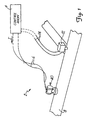
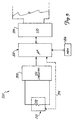
- Figure 1 is a diagram of process control system 2 including field mounted temperature transmitter 40 and a valve controller 12 coupled electrically to control room 4 over a two wire process control loops 6 and 14, respectively.
- Transmitter 40 mounted on a manifold and connected to the pipe via a manifold, monitors the process variable of process fluid in process piping 18.
- process variable sensors which include a resistance includes sensors for pressure, flow, pH, turbidity, level, etc.
- transmitter 40 is a temperature transmitter which transmits temperature information to control room 4 over loop 6 by controlling the current flowing through loop 6. For example, the current f lowing through loop 6 may be controlled between 4 and 20 mA and properly calibrated to indicate temperature.
- transmitters in accordance with the invention may transmit digital information related to temperature over loop 6 to control room 4 such as in a HART® or an all digital protocol such as Fieldbus.
- Transmitter 40 includes circuitry described herein in more detail which provides advanced diagnostics related to sensor operation.
- One aspect of the present invention includes a recognition of a close correlation, in some cases linear relationship, of the self heating (SH) index to the "alpha" of an RTD sensor.
- the alpha of a sensor is related to sensor calibration and therefore to sensor lifetime. Accordingly, if the SH index is measured, the lifetime of the sensor can be estimated. Furthermore, the sensor output can be corrected in real-time as a function of the amount of degradation (e.g., the difference between a preselected value of the SH index and the true current value of the SH index). This provides an autocorrection to the transmitter output.
- One aspect of the invention includes a new technique for determining the SH index of a resistive element in a transmitter.
- prior art self heating index measurement was performed by monitoring temperature change in the element due to an applied current.
- An embodiment of the present invention includes defining the self heating index as the change in resistance of an electrical element for a given change in the power input to the element. This technique is preferable for a process control device because it does not require the resistive element to be calibrated to temperature. Furthermore, the technique does not require the element to be removed from the process such that real-time data can be collected without the trouble and cost of interrupting the process.
- the invention can be practiced in any of a number of places in a process system control system.
- the present invention as realized in software and a microprocessor, can reside in a central controller or a final control element such as a valve, motor or switch.
- modern digital protocols such as Fieldbus, Profibus and others allow for the software which practices the present invention to be communicated between elements in a process control system, and also provide for process variables to be sensed in one transmitter and then sent to the software.
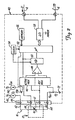
- FIG. 2 is a simplified block diagram of the invention implemented in a temperature transmitter 40 connected to RTD temperature sensor 10.
- Transmitter 40 includes terminal block 44, current source 45, multiplexer 46, differential amplifier 48, high accuracy A/D converter 50, microprocessor 52, clock circuit 54, memory 56 and input-output circuit 58.
- Terminal block 44 includes terminals 1 through 5 for coupling to, for example, RTD temperature sensor 10.
- Sensor 10 can be either internal or external to transmitter 40.
- Sensor 10 includes RTD sensor element 61 having a resistance R 1 which varies with changes in the ambient temperature.
- Leads 16 include four element leads 62, 64, 66 and 68.
- Lead 62 is connected between sensor element 61 and terminal 4
- lead 64 is connected between sensor element 61 and terminal 3
- lead 66 is connected between sensor element 61 and terminal 2
- lead 68 is connected between sensor element 61 and terminal 1.
- Current source 45 is connected to terminal block 44 and supplies a measurement current I S through terminal 4, sensor element 61, terminal 1, reference resistance R REF , pull-down resistance R 2 and ground terminal 72.
- Sensor element 61 develops a voltage drop across terminals 2 and 3 which is a function of the resistance R 1 and thus the temperature of sensor element 61.
- Reference resistor R REF is connected between terminal 1 and pull-down resistor R 2 .
- Multiplexer 46 is divided into two sections, an active multiplexer having an output connected to the non-inverting input of differential amplifier 48 and a reference multiplexer having an output connected to the inverting input of differential amplifier 48.
- Microprocessor 52 controls multiplexer 46 to multiplex appropriate sets of analog signals, including signals from terminals 1 through 3, to the non-inverting and inverting inputs of differential amplifier 48.
- Differential amplifier 48 has an output connected to A/D converter 50.
- A/D converter 50 has an accuracy of 17 bits and a conversion rate of 14 samples/second.
- A/D converter 50 converts the voltage at the output of differential amplifier 48 into a digital value and provides that value to microprocessor 52 for analysis or for communication over process control loop 6 through input-output circuit 58.
- Input-output circuit 58 in a preferred embodiment, includes a HART® communication section, a FIELDBUS communication section and a 4-20 mA analog loop section for analog or bi-directional digital communicating over loop 6 according to a selected protocol in a known manner. Other protocols can also be used, for example, a four-wire configuration may be employed in which power is received from a separate source. Loop 6 also provides power to the various components of transmitter 40 through input-output circuit 58. Preferably, transmitter 40 is wholly (completely) powered by the two-wire loop 6.
- Memory 56 stores instructions and information for microprocessor 52, which operates at a speed determined by clock circuit 60.
- Clock circuit 60 includes a real time clock and a precision high speed clock, which are also used to sequence the operation of A/D converter 50.
- Microprocessor 52 performs several functions, including control of multiplexer 46 and A/D converter 50, control of communications over loop 6, temperature compensation, storage of transmitter configuration parameters and performing sensor diagnostics.
- Microprocessor 52 employs the following equation to compute the temperature of RTD sensor element 61:
- R 1 V R1 V RREF ( R REFNOM ) where:
- Microprocessor 52 measures the voltage drop V R1 across RTD sensor element 61 between terminals 2 and 3, and the voltage drop (V RREF ) across reference resistance R REF with multiplexer 46.
- V RREF voltage drop across reference resistance R REF
- Microprocessor 52 converts the measured resistance R 1 into temperature units with a look-up table or suitable equations stored in memory 30. For example, one such equation is the Callender-Van Dusen equation which is: Where:
- the SH index is calculated when microprocessor 52 actuates switch 138 to couple current source 140 to sensor 61. P 1 and R 1 of equation 1 are calculated with current I SH from source 140 flowing through sensor 61. Microprocessor 52 determines P 2 and R 2 due to current I S from source 45. The SH index is calculated using equation 1. If transmitter 40 is completely powered from loop 6, the currents I SH and I S are limited to the current I in loop 6, less any current required to operate circuitry in transmitter 40.
- Microprocessor 52 performs diagnostics related to operation of transmitter 40 using the SH index. The following describes a number of embodiments for realizing the diagnostic circuitry in transmitter 40. Such diagnostics include determining sensor health, performing a residual lifetime estimate may be representative of an impending sensor failure, or performing an autocorrection to the temperature measurement.
- Another aspect of the present invention includes the use of the self heating index to correct the temperature measurement to reduce errors due to drift in alpha ( ⁇ ) and R 0 .
- the constant alpha ( ⁇ ) and R 0 (given in equation 2) for the sensor, changes thereby causing inaccuracies in the temperature measurements. It has been discovered that there is a substantially linear relationship between the SH index and error in the temperature measurement caused by drift in alpha ( ⁇ ) and R 0 .
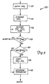
- Figure 3 is a block diagram 150 illustrating the present invention as it relates to autocorrection the temperature output as a function of the SH index.
- Diagram 150 shows operations which would typically be performed by microprocessor 52 in Figure 2.
- the previous value of the self heating index (SHI 1 ) is obtained, for example, from memory 56. This value may have been stored in memory during manufacture, previously generated by microprocessor 52 or determined and stored when the transmitter was commissioned or even at a preselected time during operation of transmitter 40.
- the current value of the SH index (SHI 2 ) is determined by microprocessor 52. If the rate of change, m is greater than or equal to a maximum allowable rate of change (m MAX ), decision block 158 provides an alarm output.
- a value representative of the difference between SHI 2 and SHI 1 is assessed at block 156.
- a preferred method for this differencing function is to calculate the slope over time of the two SHI values.
- other methods of assessing the amount of difference some as simple as comparing SHI 2 to a threshold value, can be implemented without block 156.
- the output may be transmitted, for example, over loop 6 to indicate that the sensor has degradated to such an extent that failure is imminent and replacement is necessary.
- Other types of diagnostics may also be performed such as those set forth in the parent application U.S. Serial No. 08/744,980, filed November 7, 1996.
- the value of m MAX is stored in memory 56 and may be user configurable based upon the accuracy desired for a particular process.
- the alarming function at block 158 is optional, but preferred to the present invention.
- the various functions set forth in Figure 3 may be performed remotely, in a process control device, in the control room, in a computer located off-site or in a combination of these locations.
- the invention can be practiced in any of a number of places in a process system control system.
- the present invention as realized in software and a microprocessor, can reside in a central controller or even a final control element such as a valve, motor or switch as shown in Figure 1.
- modern digital protocols such as Fieldbus, Profibus and others allow for the software which practices the present invention to be communicated between elements in a process control system, and also provide for process variables to be sensed in one transmitter and then sent to the software.
- diagnostic circuitry in the present invention uses empirical models or polynomial curve-fitting which are functions of SH index.
- a polynomial which is a function of the SH index is used for computing the residual lifetime estimate.
- the constants and/or the equations may be sent over the two wire loop to transmitter 40.
- Another diagnostic circuit is implemented with a multi-layer neural network. Although a number of training algorithms can be used to develop a neural network model for different goals, one embodiment includes the known Backpropagation Network (BPN) to develop neural network modules which will capture the nonlinear relationship among a set of input and outputs(s).
- BPN Backpropagation Network
- diagnostic circuitry 52 uses a set of if - then rules to reach a conclusion on the status of the temperature sensor RTD 61.
- the SH index is monitored and its present value is compared to upper and lower boundaries.
- the upper and lower boundaries are empirically set by testing of many RTD sensors. A decision is made based upon the comparison.
- the rate of change (ROC) of the SH index is correlated with life expectancy of sensor 61.
- the ROC of the SH index is provided to the diagnostic circuitry implemented in microprocessor 52 which provides an output indicative of expected life, including a warning when the expected remaining sensor life has dropped below a minimum value.
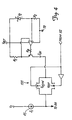
- FIG. 5 is a simplified block diagram of a process control device 200 in accordance with more general aspects of the present invention coupled to process control loop 6.
- Device 200 may be any type of process control device with an electrical element with a measurable resistance.
- Transmitter 40 of Figure 1 is one example of instrument 202.
- Device 200 includes microprocessor 202 coupled to loop 6 through I/O circuitry 204 and to a memory 206.
- Self heating circuitry 208 couples to a process control element 210 and provides a self heating signal to microprocessor 202.
- Process control element 210 includes a resistance element 212 having an electrical resistance for which a self heating value is determined by self heating circuitry 208 using the techniques in accordance with the invention.
- the connection to resistance 212 may be through a four point Kelvin connection to obtain more accurate measurements.
- a dashed line is shown between element 210 and microprocessor 202.
- Line 214 is representative of, for example, any connection or exchange of signals between element 210 and microprocessor 202.
- connection 214 provides process variable data to microprocessor 202.
- connection 214 provides a control input from microprocessor 202 to element 210.
- One aspect of the invention includes the use of self heating diagnostic techniques to perform diagnostics on any type of process control element.
- a "process control element” includes any element in a process (a transmitter, RTD, strain gauge, pick up or drive coil, etc.) which has a resistance.
- Process control devices include devices for measuring flowmeters (coriolis, magnetic, vortex, differential pressure, etc.) pressure, level, pH, turbidity temperature, etc. as well as control devices such as valve actuators, solenoids, etc.
- Some examples of process control elements include RTD 61 described above, as well as electrical coils, wiring which couples to sensors, terminations, terminal blocks, strain gauges or other types of sensors, actuators or other electrical components.
- Device 200 may comprise a coriolis flowmeter such as is described in U.S. Patent No. 5,231,884 issued August 3, 1993 in which process control element 210 is the coil used in a velocity sensor or a driver.
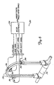
- Figure 6 is a simplified block diagram of coriolis flowmeter 230 in accordance with one embodiment of the present invention which includes a flow tube 232 and meter electronics 234. Measurement tubes 236 couple to flow tube 232, a drive coil 240 in a drive element vibrates tubes 236 in response to a drive signal and sense elements which include sense coils 242 and sense magnets 244 provide left and right velocity signals related to the resultant vibration of tubes 236.
- An RTD temperature sensor 246 provides an RTD signal related to the temperature of tube 236. Diagnostics circuitry of the present invention included in coriolis flowmeter 230 may be used to monitor coils 240 or 242 or RTD sensor 246 and responsively provide a diagnostic output.
- the present invention can detect various types of failures in process device including corrosion of an electrical component.
- an electrical component For example, in a wire, termination, coil, RTD, thermocouple, electrical trace on a printed circuit board or other electrical component which corrodes over time, there is a corresponding reduction in area which causes an increase in resistance.
- the present invention can detect such degradation prior to the ultimate failure of the device. Electrical components may degrade due to multiple uses which could also lead to eventual fatigue failure.
- the self heating techniques of the present invention can detect such fatigue. Further, a loose termination such as occurs with a "cold" solder joint can be detected as the termination degrades.
- Examples of various failures which may be detected using the present invention include a break in a coil winding, a termination or poor solder joint, a damaged trace on a circuit board, a poor wire wrap termination, a error in soldering, a poor connector damaged to a wire or component due to handling, damage to a wire component due to temperature cycling.
- a failure may be detected, for example, at block 158 in which the change in self heating index ( ⁇ SHI) may be compared with a threshold and used to indicate a failure mode.
- the diagnostic output is used to compensate for the degradation in the electrical element. For example, the output from a sensor may be compensated as well as the input signal provided to a control element.
Landscapes
- Physics & Mathematics (AREA)
- General Physics & Mathematics (AREA)
- Engineering & Computer Science (AREA)
- Automation & Control Theory (AREA)
- Arrangements For Transmission Of Measured Signals (AREA)
- Control Of Temperature (AREA)
- Measuring Volume Flow (AREA)
- Testing And Monitoring For Control Systems (AREA)
- Measuring Temperature Or Quantity Of Heat (AREA)
Description
- The present invention relates to equipment of the type used in the process control industry. More specifically, the invention relates to diagnostics for process control device in which the diagnostics is a function of a resistance.
- Process control devices are used to monitor process variables and control industrial processes. For example, a process control transmitter might monitor temperature and transmit such information back to a control room. Furthermore, a process controller such as a valve controller is used to control the process.
- As sensors control elements or other components, or are subjected to harsh environmental conditions, the accuracy of the system tends to degrade. It is possible to compensate for this degradation by periodically recalibrating the device. Typically, this requires an operator to enter the field and perform a calibration process on-site on the device. This is both inconvenient and time consuming for the operator. Further, it is difficult to determine the condition of a device, prior to its ultimate failure.
- It is also necessary for the device or their components to be periodically replaced as they age. However, it is difficult to determine precisely when such replacement is necessary. Therefore, components are typically replaced well before their failure or, in some cases, they may fail unexpectedly requiring an unscheduled system shutdown.
- The invention is defined by
independent claims - A device in a process control system includes an electrical element which has a resistance. Self heating circuitry coupled to the element provides a self heating signal related to the resistance of the electrical element. Diagnostic circuitry provides an output as a function of the self heating signal output, for example, a residual life estimate of the element or a calibration output.
-
- Figure 1 shows a process control system including a transmitter in accordance with the present invention.
- Figure 2 is a block diagram of a transmitter of the present invention.
- Figure 3 is a simplified block diagram of a transmitter in accordance with one embodiment of the invention.
- Figure 4 is a simplified block diagram in accordance with an embodiment of the present invention.
- Figure 5 is a simplified block diagram of a process control device in accordance with the invention.
- Figure 6 is a simplified diagram of a coriolis flowmeter in accordance with one embodiment of the invention.
-
- Figure 1 is a diagram of
process control system 2 including field mountedtemperature transmitter 40 and avalve controller 12 coupled electrically to controlroom 4 over a two wire process control loops 6 and 14, respectively.Transmitter 40, mounted on a manifold and connected to the pipe via a manifold, monitors the process variable of process fluid in process piping 18. The present invention applies to any electrical element in a process control device. Examples of process variable sensors which include a resistance includes sensors for pressure, flow, pH, turbidity, level, etc. In one embodiment,transmitter 40 is a temperature transmitter which transmits temperature information to controlroom 4 over loop 6 by controlling the current flowing through loop 6. For example, the current f lowing through loop 6 may be controlled between 4 and 20 mA and properly calibrated to indicate temperature. Additionally or in the alternative, transmitters in accordance with the invention may transmit digital information related to temperature over loop 6 to controlroom 4 such as in a HART® or an all digital protocol such as Fieldbus.Transmitter 40 includes circuitry described herein in more detail which provides advanced diagnostics related to sensor operation. - One aspect of the present invention includes a recognition of a close correlation, in some cases linear relationship, of the self heating (SH) index to the "alpha" of an RTD sensor. As is known, the alpha of a sensor is related to sensor calibration and therefore to sensor lifetime. Accordingly, if the SH index is measured, the lifetime of the sensor can be estimated. Furthermore, the sensor output can be corrected in real-time as a function of the amount of degradation (e.g., the difference between a preselected value of the SH index and the true current value of the SH index). This provides an autocorrection to the transmitter output.
- One aspect of the invention includes a new technique for determining the SH index of a resistive element in a transmitter. Typically, prior art self heating index measurement was performed by monitoring temperature change in the element due to an applied current. However, in a process control device it is impractical to perform such a measurement due to power limitations and the necessity of a separate temperature measurement. An embodiment of the present invention includes defining the self heating index as the change in resistance of an electrical element for a given change in the power input to the element. This technique is preferable for a process control device because it does not require the resistive element to be calibrated to temperature. Furthermore, the technique does not require the element to be removed from the process such that real-time data can be collected without the trouble and cost of interrupting the process. The self heating index can be calculated in a process control device by applying two different input currents I1, I2 for example, 5 mA and 15mA to the electrical element. The resulting voltages across the resistance are measured and the resistance of the element is calculated at the two different currents using, for example, the equation R = V/I. The power P1, P2 applied to the element is determined at the two different currents as P = I·V. The self heating index is calculated in accordance with equation 1:
P - The invention can be practiced in any of a number of places in a process system control system. In particular, the present invention as realized in software and a microprocessor, can reside in a central controller or a final control element such as a valve, motor or switch. Furthermore, modern digital protocols such as Fieldbus, Profibus and others allow for the software which practices the present invention to be communicated between elements in a process control system, and also provide for process variables to be sensed in one transmitter and then sent to the software.
- Figure 2 is a simplified block diagram of the invention implemented in a
temperature transmitter 40 connected to RTD temperature sensor 10.Transmitter 40 includesterminal block 44,current source 45,multiplexer 46,differential amplifier 48, high accuracy A/D converter 50,microprocessor 52,clock circuit 54,memory 56 and input-output circuit 58. -
Terminal block 44 includesterminals 1 through 5 for coupling to, for example, RTD temperature sensor 10. Sensor 10 can be either internal or external totransmitter 40. Sensor 10 includes RTD sensor element 61 having a resistance R1 which varies with changes in the ambient temperature.Leads 16 include four element leads 62, 64, 66 and 68. Lead 62 is connected between sensor element 61 andterminal 4, lead 64 is connected between sensor element 61 and terminal 3, lead 66 is connected between sensor element 61 andterminal 2, andlead 68 is connected between sensor element 61 andterminal 1. -
Current source 45 is connected toterminal block 44 and supplies a measurement current IS throughterminal 4, sensor element 61,terminal 1, reference resistance RREF, pull-down resistance R2 andground terminal 72. Sensor element 61 develops a voltage drop acrossterminals 2 and 3 which is a function of the resistance R1 and thus the temperature of sensor element 61. Reference resistor RREF is connected betweenterminal 1 and pull-down resistor R2. -
Multiplexer 46 is divided into two sections, an active multiplexer having an output connected to the non-inverting input ofdifferential amplifier 48 and a reference multiplexer having an output connected to the inverting input ofdifferential amplifier 48.Microprocessor 52 controls multiplexer 46 to multiplex appropriate sets of analog signals, including signals fromterminals 1 through 3, to the non-inverting and inverting inputs ofdifferential amplifier 48.Differential amplifier 48 has an output connected to A/D converter 50. In one embodiment, A/D converter 50 has an accuracy of 17 bits and a conversion rate of 14 samples/second. A/D converter 50 converts the voltage at the output ofdifferential amplifier 48 into a digital value and provides that value tomicroprocessor 52 for analysis or for communication over process control loop 6 through input-output circuit 58. - Input-
output circuit 58, in a preferred embodiment, includes a HART® communication section, a FIELDBUS communication section and a 4-20 mA analog loop section for analog or bi-directional digital communicating over loop 6 according to a selected protocol in a known manner. Other protocols can also be used, for example, a four-wire configuration may be employed in which power is received from a separate source. Loop 6 also provides power to the various components oftransmitter 40 through input-output circuit 58. Preferably,transmitter 40 is wholly (completely) powered by the two-wire loop 6. -
Memory 56 stores instructions and information formicroprocessor 52, which operates at a speed determined by clock circuit 60. Clock circuit 60 includes a real time clock and a precision high speed clock, which are also used to sequence the operation of A/D converter 50.Microprocessor 52 performs several functions, including control ofmultiplexer 46 and A/D converter 50, control of communications over loop 6, temperature compensation, storage of transmitter configuration parameters and performing sensor diagnostics. -
Microprocessor 52 employs the following equation to compute the temperature of RTD sensor element 61:R - R1 =
- resistance of RTD sensor element 61;
- VR1 =
- voltage drop across the RTD sensor element 61;
- VRREF =
- voltage drop across resistance RREF; and
- RREFNOM =
- nominal resistance of the reference
resistance RREF in Ohms, and/or stored in
memory 56. -
Microprocessor 52 measures the voltage drop VR1 across RTD sensor element 61 betweenterminals 2 and 3, and the voltage drop (VRREF) across reference resistance RREF withmultiplexer 46. In a four-wire resistance measurement such as the one shown in Figure 2, the voltage drop across the connections toterminals 2 and 3 is largely eliminated, since substantially all of the current IS flows betweenterminals Microprocessor 52 converts the measured resistance R1 into temperature units with a look-up table or suitable equations stored in memory 30. For example, one such equation is the Callender-Van Dusen equation which is:Where:
- R(t) =
- Resistance at temperature t, in Ohms.
- R0 =
- Resistance at temperature O, Ohm.
- t =
- Temperature, deg C.
- α, δ, β =
- Calibration constants.
- β =
- 0 for t>0 deg C.
- However, both stored lookup tables or the
equation 2 must be properly calibrated for a particular RTD temperature sensor. Further, such calibration tends to change over time as the alpha (α) for the sensor drifts. Calibrating an RTD requires an accurate thermometer reference to obtain a number of correct temperature values in order to accurately determine the constants α, R0 and δ. Equation 3 and transmitter calibration are discussed in PRT Handbook Bulletin 1042, dated February 1985, published by Rosemount and incorporated by reference into this application. - The SH index is calculated when
microprocessor 52 actuates switch 138 to couplecurrent source 140 to sensor 61. P1 and R1 ofequation 1 are calculated with current ISH fromsource 140 flowing through sensor 61.Microprocessor 52 determines P2 and R2 due to current IS fromsource 45. The SH index is calculated usingequation 1. Iftransmitter 40 is completely powered from loop 6, the currents ISH and IS are limited to the current I in loop 6, less any current required to operate circuitry intransmitter 40. -
Microprocessor 52 performs diagnostics related to operation oftransmitter 40 using the SH index. The following describes a number of embodiments for realizing the diagnostic circuitry intransmitter 40. Such diagnostics include determining sensor health, performing a residual lifetime estimate may be representative of an impending sensor failure, or performing an autocorrection to the temperature measurement. - Another aspect of the present invention includes the use of the self heating index to correct the temperature measurement to reduce errors due to drift in alpha (α) and R0. As the RTD sensor ages, the constant alpha (α) and R0 (given in equation 2) for the sensor, changes thereby causing inaccuracies in the temperature measurements. It has been discovered that there is a substantially linear relationship between the SH index and error in the temperature measurement caused by drift in alpha (α) and R0. The temperature can be corrected using the equation:
- Tmeasured is the measured temperature;
- K is a constant of proportionality;
- ΔSHI is the change in the self heating index; and
- Tcorrected is the autocorrected temperature.
-
- Figure 3 is a block diagram 150 illustrating the present invention as it relates to autocorrection the temperature output as a function of the SH index. Diagram 150 shows operations which would typically be performed by
microprocessor 52 in Figure 2. Atblock 152, the previous value of the self heating index (SHI1) is obtained, for example, frommemory 56. This value may have been stored in memory during manufacture, previously generated bymicroprocessor 52 or determined and stored when the transmitter was commissioned or even at a preselected time during operation oftransmitter 40. Atblock 154 the current value of the SH index (SHI2) is determined bymicroprocessor 52. If the rate of change, m is greater than or equal to a maximum allowable rate of change (mMAX),decision block 158 provides an alarm output. In general, a value representative of the difference between SHI2 and SHI1 is assessed atblock 156. A preferred method for this differencing function is to calculate the slope over time of the two SHI values. However, other methods of assessing the amount of difference, some as simple as comparing SHI2 to a threshold value, can be implemented withoutblock 156. The output may be transmitted, for example, over loop 6 to indicate that the sensor has degradated to such an extent that failure is imminent and replacement is necessary. Other types of diagnostics may also be performed such as those set forth in the parent application U.S. Serial No. 08/744,980, filed November 7, 1996. The value of mMAX is stored inmemory 56 and may be user configurable based upon the accuracy desired for a particular process. The alarming function atblock 158 is optional, but preferred to the present invention. - If the alarm condition does not exist, control passes to decision block 160 in which the measured self heating index (SHI2) is compared with the stored self heating index (SHI1). If they are approximately the same, control is passed to block 162 and the temperature is determined. If, on the other hand, there is a difference between the two values, a new value for the ΔSHI in
equation 4 is calculated bymicroprocessor 52 atblock 164. Further, other more complex curve fitting techniques can be used to correlate SHI with sensor calibration. Control is passed to block 162 and the new value for ASHI inequation 4 is used in determining temperature. The new value for ΔSHI is stored in memory to replace the previous value. - The various functions set forth in Figure 3 may be performed remotely, in a process control device, in the control room, in a computer located off-site or in a combination of these locations. Generally, the invention can be practiced in any of a number of places in a process system control system. For example, the present invention as realized in software and a microprocessor, can reside in a central controller or even a final control element such as a valve, motor or switch as shown in Figure 1. Furthermore, modern digital protocols such as Fieldbus, Profibus and others allow for the software which practices the present invention to be communicated between elements in a process control system, and also provide for process variables to be sensed in one transmitter and then sent to the software.
- One embodiment of diagnostic circuitry in the present invention uses empirical models or polynomial curve-fitting which are functions of SH index. For example, a polynomial which is a function of the SH index is used for computing the residual lifetime estimate. The constants and/or the equations may be sent over the two wire loop to
transmitter 40. Another diagnostic circuit is implemented with a multi-layer neural network. Although a number of training algorithms can be used to develop a neural network model for different goals, one embodiment includes the known Backpropagation Network (BPN) to develop neural network modules which will capture the nonlinear relationship among a set of input and outputs(s). - Another embodiment of
diagnostic circuitry 52 uses a set of if - then rules to reach a conclusion on the status of the temperature sensor RTD 61. The SH index is monitored and its present value is compared to upper and lower boundaries. The upper and lower boundaries are empirically set by testing of many RTD sensors. A decision is made based upon the comparison. - In another aspect of the invention, the rate of change (ROC) of the SH index is correlated with life expectancy of sensor 61. The ROC of the SH index is provided to the diagnostic circuitry implemented in
microprocessor 52 which provides an output indicative of expected life, including a warning when the expected remaining sensor life has dropped below a minimum value. - Figure 5 is a simplified block diagram of a
process control device 200 in accordance with more general aspects of the present invention coupled to process control loop 6.Device 200 may be any type of process control device with an electrical element with a measurable resistance.Transmitter 40 of Figure 1 is one example ofinstrument 202.Device 200 includesmicroprocessor 202 coupled to loop 6 through I/O circuitry 204 and to amemory 206.Self heating circuitry 208 couples to aprocess control element 210 and provides a self heating signal tomicroprocessor 202.Process control element 210 includes aresistance element 212 having an electrical resistance for which a self heating value is determined byself heating circuitry 208 using the techniques in accordance with the invention. The connection toresistance 212 may be through a four point Kelvin connection to obtain more accurate measurements. A dashed line is shown betweenelement 210 andmicroprocessor 202.Line 214 is representative of, for example, any connection or exchange of signals betweenelement 210 andmicroprocessor 202. For example, ifelement 210 is a process variable sensor,connection 214 provides process variable data tomicroprocessor 202. Similarly, ifelement 210 is a control element,connection 214 provides a control input frommicroprocessor 202 toelement 210. One aspect of the invention includes the use of self heating diagnostic techniques to perform diagnostics on any type of process control element. For example, as used herein, a "process control element" includes any element in a process (a transmitter, RTD, strain gauge, pick up or drive coil, etc.) which has a resistance. Process control devices include devices for measuring flowmeters (coriolis, magnetic, vortex, differential pressure, etc.) pressure, level, pH, turbidity temperature, etc. as well as control devices such as valve actuators, solenoids, etc. Some examples of process control elements include RTD 61 described above, as well as electrical coils, wiring which couples to sensors, terminations, terminal blocks, strain gauges or other types of sensors, actuators or other electrical components. -
Device 200 may comprise a coriolis flowmeter such as is described in U.S. Patent No. 5,231,884 issued August 3, 1993 in whichprocess control element 210 is the coil used in a velocity sensor or a driver. For example, Figure 6 is a simplified block diagram of coriolis flowmeter 230 in accordance with one embodiment of the present invention which includes aflow tube 232 andmeter electronics 234.Measurement tubes 236 couple to flowtube 232, a drive coil 240 in a drive element vibratestubes 236 in response to a drive signal and sense elements which include sense coils 242 andsense magnets 244 provide left and right velocity signals related to the resultant vibration oftubes 236. AnRTD temperature sensor 246 provides an RTD signal related to the temperature oftube 236. Diagnostics circuitry of the present invention included in coriolis flowmeter 230 may be used to monitorcoils 240 or 242 orRTD sensor 246 and responsively provide a diagnostic output. - Thus, the present invention can detect various types of failures in process device including corrosion of an electrical component. For example, in a wire, termination, coil, RTD, thermocouple, electrical trace on a printed circuit board or other electrical component which corrodes over time, there is a corresponding reduction in area which causes an increase in resistance. The present invention can detect such degradation prior to the ultimate failure of the device. Electrical components may degrade due to multiple uses which could also lead to eventual fatigue failure. The self heating techniques of the present invention can detect such fatigue. Further, a loose termination such as occurs with a "cold" solder joint can be detected as the termination degrades.
- Examples of various failures which may be detected using the present invention include a break in a coil winding, a termination or poor solder joint, a damaged trace on a circuit board, a poor wire wrap termination, a error in soldering, a poor connector damaged to a wire or component due to handling, damage to a wire component due to temperature cycling. Referring back to Figure 3, such a failure may be detected, for example, at
block 158 in which the change in self heating index (ΔSHI) may be compared with a threshold and used to indicate a failure mode. In another aspect of the invention, the diagnostic output is used to compensate for the degradation in the electrical element. For example, the output from a sensor may be compensated as well as the input signal provided to a control element. - Although the present invention has been described with reference to preferred embodiments, workers skilled in the art will recognize that changes may be made in form and detail without departing from the invention.
Claims (22)
- A process control device in a process control system, comprising:an electrical element having an electrical resistance;process control device circuitry coupled to the electrical element to perform a process control function;self heating circuitry coupled to the electrical element providing a self heating signal related to a self heating (SH) index of the electrical element due to its electrical resistance;circuitry coupled to a process control loop for coupling the device to the loop; anddiagnostic circuitry coupled to the self heating circuitry responsively providing a diagnostic output related to health of the electrical element as a function of the self heating signal.
- The device of Claim 1 including a memory storing at least one expected result related to the self heating signal.
- The device of Claim 1 or Claim 2 wherein the diagnostic circuitry comprises a neural network and/or regression models.
- The device of any one of Claims 1 to 3 wherein the diagnostic output is related to a residual lifetime estimate for the electrical element.
- The device of Claim 4 wherein the diagnostic circuitry determines the residual lifetime estimate as a function of rate of change (ROC) of the self heating signal.
- The device of any one of Claims 1 to 5 wherein the self heating circuitry includes a current source and voltage measurement circuitry.
- The device of any one of Claims 1 to 6 wherein the self heating circuitry determines the SH index as a function of a change in resistance of the electrical element in response to to a change in power applied to the electrical element.
- The device of any one of Claims 1 to 7 wherein the output circuitry calibrates the electrical element as a function of the self heating signal.
- The device of any one of Claims 1 to 8 wherein the electrical element is a coil and the coil comprises a sensor in or a driver of a coriolis flowmeter.
- A device for use in a process control system comprising:I/O circuitry adapted to be coupled to a process control loop;an electrical element having a resistance;a current source coupled to the electrical element to inject a current into the electrical element;voltage measurement circuitry coupled to the electrical element providing an output related to voltage drop across the electrical element; anddiagnostic circuitry providing a self heating (SH) index output, indicative of the health of the electric element, as a function of injected current and the voltage, drop across the electrical element due to its resistance.
- The device of Claim 10 wherein the diagnostic circuitry provides a life expectancy output of the electrical element as a function of the SH index.
- The device of Claim 10 or Claim 11 including measurement circuitry providing an output related to a process variable as a function of an output from the electrical element and the SH index.
- The device of any one of Claims 1 to 12 wherein the SH index is determined as a function of a change in resistance of the electrical element in response to a change in power applied to the electrical element.
- The device of Claim 13 wherein the SH index is calculated as (R1-R2)/(P1-P2). where R1 and R2 are values of resistance of the element at two different currents I1, I2 and corresponding measured voltages, and P1 and P2 are the values of power so applied to the element and determined at currents I1, I2 respectively.
- The device of any one of Claims 1 to 14 wherein the electrical element comprises a strain gauge, a control element, a sense element, a coil and/or a thermocouple.
- A method for diagnosing an electrical element in a process control device, comprising:obtaining a self heating (SH) index for an electrical element of the device, the electrical element having a resistance;providing an electrical element diagnostic output as a function of the SH index.
- The method of Claim 16 wherein obtaining the SH index comprises measuring change in resistance of the electrical element in response to a change in power applied to the electrical element.
- The method of Claim 16 or Claim 17 wherein the SH index is calculated as (R1-R2)/P1-P2) where R1 and R2 are values of resistance of the element at two different currents I1, I2 and corresponding measured voltages, and P1 and P2 are the values of power so applied to the element and determined at currents I1, I2 respectively.
- The method of any one of Claims 16 to 18 including estimating residual life of the electrical element based upon a rate of change of the SH index.
- The method of Claim 19 wherein obtaining the SH index includes sequentially injecting at least two different current levels into the electrical element and measuring the resultant voltage drop across the electrical element.
- The method of any one of Claims 16 to 20 including determining life expectancy of the electrical element as a function of the diagnostic output.
- The method of any one of Claims 16 to 21 including calibrating the electrical element as a function of the SH index.
Applications Claiming Priority (3)
| Application Number | Priority Date | Filing Date | Title |
|---|---|---|---|
| US13844698A | 1998-08-21 | 1998-08-21 | |
| US138446 | 1998-08-21 | ||
| PCT/US1999/018264 WO2000011524A1 (en) | 1998-08-21 | 1999-08-11 | Resistance based process control device diagnostics |
Publications (2)
| Publication Number | Publication Date |
|---|---|
| EP1105781A1 EP1105781A1 (en) | 2001-06-13 |
| EP1105781B1 true EP1105781B1 (en) | 2004-01-07 |
Family
ID=22482051
Family Applications (1)
| Application Number | Title | Priority Date | Filing Date |
|---|---|---|---|
| EP99941064A Expired - Lifetime EP1105781B1 (en) | 1998-08-21 | 1999-08-11 | Resistance based process control device diagnostics |
Country Status (7)
| Country | Link |
|---|---|
| EP (1) | EP1105781B1 (en) |
| JP (1) | JP4738596B2 (en) |
| CN (1) | CN1282048C (en) |
| AU (1) | AU5478899A (en) |
| DE (1) | DE69914086T2 (en) |
| HK (1) | HK1039807B (en) |
| WO (1) | WO2000011524A1 (en) |
Families Citing this family (9)
| Publication number | Priority date | Publication date | Assignee | Title |
|---|---|---|---|---|
| US7262693B2 (en) * | 2004-06-28 | 2007-08-28 | Rosemount Inc. | Process field device with radio frequency communication |
| US8509926B2 (en) * | 2005-12-05 | 2013-08-13 | Fisher-Rosemount Systems, Inc. | Self-diagnostic process control loop for a process plant |
| US9217653B2 (en) * | 2007-09-13 | 2015-12-22 | Rosemount Inc. | High performance architecture for process transmitters |
| SE537114C2 (en) * | 2011-07-08 | 2015-01-20 | Scania Cv Ab | Method for testing temperature sensors, and a test device |
| KR101338674B1 (en) * | 2012-08-10 | 2013-12-19 | 엘에스산전 주식회사 | Hart analog input module with differential input stage |
| WO2015102070A1 (en) * | 2014-01-06 | 2015-07-09 | 株式会社神戸製鋼所 | Deterioration detector and thermocouple inspection device |
| JP6225032B2 (en) * | 2014-01-06 | 2017-11-01 | 株式会社神戸製鋼所 | Thermocouple inspection device and thermocouple inspection method |
| JP6325255B2 (en) * | 2014-01-06 | 2018-05-16 | 株式会社神戸製鋼所 | Deterioration detector |
| CN113701921A (en) * | 2021-08-30 | 2021-11-26 | 上海仪器仪表自控系统检验测试所有限公司 | Method for measuring self-heating index of thermal resistance thermometer |
Family Cites Families (15)
| Publication number | Priority date | Publication date | Assignee | Title |
|---|---|---|---|---|
| US4399824A (en) * | 1981-10-05 | 1983-08-23 | Air-Shields, Inc. | Apparatus for detecting probe dislodgement |
| JPS62121527A (en) * | 1985-11-22 | 1987-06-02 | Hitachi Ltd | Magnetic disk controller |
| JPS62121527U (en) * | 1986-01-24 | 1987-08-01 | ||
| JPH0781916B2 (en) * | 1988-07-05 | 1995-09-06 | 株式会社村田製作所 | Temperature measuring device |
| DE4008560C2 (en) * | 1989-03-17 | 1995-11-02 | Hitachi Ltd | Method and device for determining the remaining service life of an aggregate |
| US5269311A (en) * | 1989-08-29 | 1993-12-14 | Abbott Laboratories | Method for compensating errors in a pressure transducer |
| JPH0447258A (en) * | 1990-06-14 | 1992-02-17 | Yamatake Honeywell Co Ltd | Estimating apparatus for lifetime of resistor |
| JPH0476799A (en) * | 1990-07-19 | 1992-03-11 | Yamatake Honeywell Co Ltd | Device for deciding and forecasting service life of thermocouple temperature sensor |
| JPH07225530A (en) * | 1994-02-15 | 1995-08-22 | Canon Inc | Diagnostic device for image recording thermal fixing device and image recorder |
| CN1141679A (en) * | 1994-02-23 | 1997-01-29 | 罗斯蒙德公司 | Field transmitter for storing information |
| JP3133613B2 (en) * | 1994-07-27 | 2001-02-13 | キヤノン株式会社 | Method for measuring durability of substrate for ink jet recording head |
| JPH08221118A (en) * | 1995-02-13 | 1996-08-30 | Hitachi Ltd | Intelligent transmitter |
| US5708585A (en) * | 1995-03-20 | 1998-01-13 | General Motors Corporation | Combustible gas measurement |
| US5828567A (en) * | 1996-11-07 | 1998-10-27 | Rosemount Inc. | Diagnostics for resistance based transmitter |
| JPH10159639A (en) * | 1996-11-27 | 1998-06-16 | Toyota Motor Corp | Detecting method for abnormality of temperature sensor |
-
1999
- 1999-08-11 CN CNB998098795A patent/CN1282048C/en not_active Expired - Fee Related
- 1999-08-11 WO PCT/US1999/018264 patent/WO2000011524A1/en active IP Right Grant
- 1999-08-11 EP EP99941064A patent/EP1105781B1/en not_active Expired - Lifetime
- 1999-08-11 DE DE69914086T patent/DE69914086T2/en not_active Expired - Lifetime
- 1999-08-11 JP JP2000566725A patent/JP4738596B2/en not_active Expired - Lifetime
- 1999-08-11 AU AU54788/99A patent/AU5478899A/en not_active Abandoned
-
2002
- 2002-01-24 HK HK02100551.9A patent/HK1039807B/en not_active IP Right Cessation
Also Published As
| Publication number | Publication date |
|---|---|
| HK1039807A1 (en) | 2002-05-10 |
| WO2000011524A1 (en) | 2000-03-02 |
| JP4738596B2 (en) | 2011-08-03 |
| EP1105781A1 (en) | 2001-06-13 |
| DE69914086T2 (en) | 2004-09-09 |
| CN1313964A (en) | 2001-09-19 |
| CN1282048C (en) | 2006-10-25 |
| JP2002523820A (en) | 2002-07-30 |
| DE69914086D1 (en) | 2004-02-12 |
| AU5478899A (en) | 2000-03-14 |
| HK1039807B (en) | 2007-02-16 |
Similar Documents
| Publication | Publication Date | Title |
|---|---|---|
| US6449574B1 (en) | Resistance based process control device diagnostics | |
| US6434504B1 (en) | Resistance based process control device diagnostics | |
| US6519546B1 (en) | Auto correcting temperature transmitter with resistance based sensor | |
| US6754601B1 (en) | Diagnostics for resistive elements of process devices | |
| EP0937294B1 (en) | Diagnostics for resistance based transmitter | |
| JP5575986B2 (en) | Process fluid temperature measuring instrument | |
| EP1247268B1 (en) | Low power two-wire self validating temperature transmitter | |
| US7280048B2 (en) | Process control loop current verification | |
| EP2867634B1 (en) | Industrial process temperature transmitter with sensor stress diagnostics | |
| AU678596B2 (en) | Field transmitter built-in test equipment | |
| US7963173B2 (en) | Magnetic flowmeter for measuring flow | |
| JP5548266B2 (en) | Process variable transmitter with diagnostic function for 2-wire process control loop | |
| CA2222681A1 (en) | Open sensor diagnostic system for temperature transmitter in a process control system | |
| EP1105781B1 (en) | Resistance based process control device diagnostics | |
| KR20050017572A (en) | Method for Compensating Error in Manufacturing Process of Calorimeter |
Legal Events
| Date | Code | Title | Description |
|---|---|---|---|
| PUAI | Public reference made under article 153(3) epc to a published international application that has entered the european phase |
Free format text: ORIGINAL CODE: 0009012 |
|
| 17P | Request for examination filed |
Effective date: 20010220 |
|
| AK | Designated contracting states |
Kind code of ref document: A1 Designated state(s): AT BE CH CY DE DK ES FI FR GB GR IE IT LI LU MC NL PT SE |
|
| GRAH | Despatch of communication of intention to grant a patent |
Free format text: ORIGINAL CODE: EPIDOS IGRA |
|
| GRAS | Grant fee paid |
Free format text: ORIGINAL CODE: EPIDOSNIGR3 |
|
| GRAA | (expected) grant |
Free format text: ORIGINAL CODE: 0009210 |
|
| AK | Designated contracting states |
Kind code of ref document: B1 Designated state(s): CH DE GB LI |
|
| REG | Reference to a national code |
Ref country code: GB Ref legal event code: FG4D |
|
| REG | Reference to a national code |
Ref country code: CH Ref legal event code: EP |
|
| REG | Reference to a national code |
Ref country code: IE Ref legal event code: FG4D |
|
| REF | Corresponds to: |
Ref document number: 69914086 Country of ref document: DE Date of ref document: 20040212 Kind code of ref document: P |
|
| REG | Reference to a national code |
Ref country code: CH Ref legal event code: NV Representative=s name: KIRKER & CIE SA |
|
| PLBE | No opposition filed within time limit |
Free format text: ORIGINAL CODE: 0009261 |
|
| STAA | Information on the status of an ep patent application or granted ep patent |
Free format text: STATUS: NO OPPOSITION FILED WITHIN TIME LIMIT |
|
| 26N | No opposition filed |
Effective date: 20041008 |
|
| REG | Reference to a national code |
Ref country code: IE Ref legal event code: MM4A |
|
| PGFP | Annual fee paid to national office [announced via postgrant information from national office to epo] |
Ref country code: GB Payment date: 20110825 Year of fee payment: 13 |
|
| GBPC | Gb: european patent ceased through non-payment of renewal fee |
Effective date: 20120811 |
|
| PG25 | Lapsed in a contracting state [announced via postgrant information from national office to epo] |
Ref country code: GB Free format text: LAPSE BECAUSE OF NON-PAYMENT OF DUE FEES Effective date: 20120811 |
|
| PGFP | Annual fee paid to national office [announced via postgrant information from national office to epo] |
Ref country code: DE Payment date: 20170829 Year of fee payment: 19 Ref country code: CH Payment date: 20170827 Year of fee payment: 19 |
|
| REG | Reference to a national code |
Ref country code: DE Ref legal event code: R119 Ref document number: 69914086 Country of ref document: DE |
|
| REG | Reference to a national code |
Ref country code: CH Ref legal event code: PL |
|
| PG25 | Lapsed in a contracting state [announced via postgrant information from national office to epo] |
Ref country code: CH Free format text: LAPSE BECAUSE OF NON-PAYMENT OF DUE FEES Effective date: 20180831 Ref country code: LI Free format text: LAPSE BECAUSE OF NON-PAYMENT OF DUE FEES Effective date: 20180831 |
|
| PG25 | Lapsed in a contracting state [announced via postgrant information from national office to epo] |
Ref country code: DE Free format text: LAPSE BECAUSE OF NON-PAYMENT OF DUE FEES Effective date: 20190301 |