EP1104847A2 - Inclined jet nozzle - Google Patents
Inclined jet nozzle Download PDFInfo
- Publication number
- EP1104847A2 EP1104847A2 EP00125672A EP00125672A EP1104847A2 EP 1104847 A2 EP1104847 A2 EP 1104847A2 EP 00125672 A EP00125672 A EP 00125672A EP 00125672 A EP00125672 A EP 00125672A EP 1104847 A2 EP1104847 A2 EP 1104847A2
- Authority
- EP
- European Patent Office
- Prior art keywords
- nozzle
- primary
- angle
- nozzles
- engine
- Prior art date
- Legal status (The legal status is an assumption and is not a legal conclusion. Google has not performed a legal analysis and makes no representation as to the accuracy of the status listed.)
- Granted
Links
- 230000001737 promoting effect Effects 0.000 claims abstract description 3
- 238000000034 method Methods 0.000 description 2
- 238000010790 dilution Methods 0.000 description 1
- 239000012895 dilution Substances 0.000 description 1
- 230000000694 effects Effects 0.000 description 1
Images
Classifications
-
- F—MECHANICAL ENGINEERING; LIGHTING; HEATING; WEAPONS; BLASTING
- F02—COMBUSTION ENGINES; HOT-GAS OR COMBUSTION-PRODUCT ENGINE PLANTS
- F02K—JET-PROPULSION PLANTS
- F02K1/00—Plants characterised by the form or arrangement of the jet pipe or nozzle; Jet pipes or nozzles peculiar thereto
- F02K1/46—Nozzles having means for adding air to the jet or for augmenting the mixing region between the jet and the ambient air, e.g. for silencing
-
- F—MECHANICAL ENGINEERING; LIGHTING; HEATING; WEAPONS; BLASTING
- F02—COMBUSTION ENGINES; HOT-GAS OR COMBUSTION-PRODUCT ENGINE PLANTS
- F02K—JET-PROPULSION PLANTS
- F02K1/00—Plants characterised by the form or arrangement of the jet pipe or nozzle; Jet pipes or nozzles peculiar thereto
- F02K1/28—Plants characterised by the form or arrangement of the jet pipe or nozzle; Jet pipes or nozzles peculiar thereto using fluid jets to influence the jet flow
- F02K1/34—Plants characterised by the form or arrangement of the jet pipe or nozzle; Jet pipes or nozzles peculiar thereto using fluid jets to influence the jet flow for attenuating noise
-
- F—MECHANICAL ENGINEERING; LIGHTING; HEATING; WEAPONS; BLASTING
- F05—INDEXING SCHEMES RELATING TO ENGINES OR PUMPS IN VARIOUS SUBCLASSES OF CLASSES F01-F04
- F05D—INDEXING SCHEME FOR ASPECTS RELATING TO NON-POSITIVE-DISPLACEMENT MACHINES OR ENGINES, GAS-TURBINES OR JET-PROPULSION PLANTS
- F05D2260/00—Function
- F05D2260/96—Preventing, counteracting or reducing vibration or noise
-
- Y—GENERAL TAGGING OF NEW TECHNOLOGICAL DEVELOPMENTS; GENERAL TAGGING OF CROSS-SECTIONAL TECHNOLOGIES SPANNING OVER SEVERAL SECTIONS OF THE IPC; TECHNICAL SUBJECTS COVERED BY FORMER USPC CROSS-REFERENCE ART COLLECTIONS [XRACs] AND DIGESTS
- Y02—TECHNOLOGIES OR APPLICATIONS FOR MITIGATION OR ADAPTATION AGAINST CLIMATE CHANGE
- Y02T—CLIMATE CHANGE MITIGATION TECHNOLOGIES RELATED TO TRANSPORTATION
- Y02T50/00—Aeronautics or air transport
- Y02T50/60—Efficient propulsion technologies, e.g. for aircraft
Definitions
- the invention relates to arrangement of the propulsion nozzles for gas turbine engines in particular to by-pass gas turbine engines.
- Control of the mixing and distribution of the exhaust jet plumes can be used to reduce the noise from gas turbine engines.
- Several methods have been tried to effect this and have resulted in differing degrees of effectiveness. Most methods result in significant thrust losses or increased weight.
- US 4,288,984 discloses a number of ways in which the mixing and distribution of the exhaust jet plumes is controlled in a by-pass engine. These include having a swept, canted or off-set primary nozzle.
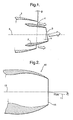
- Figure 1 shows a scarfed nozzle arrangement according to one aspect of the invention.
- Figure 2 shows a schematic cross-section of a nozzle according to the invention.
- Figure 1 shows an arrangement of primary and secondary nozzles, denoted I and 2 respectively, of a by-pass gas turbine engine. Both of these nozzle have oblique "cut-off ends" 3, 4 i.e. they are truncated at angles of ⁇ and ⁇ relative to the perpendicular of the longitudinal axis of the nozzles - the common central axis 5. The direction of the cutoffs are opposite with respect to the central axis 5.
- the oblique cut-off edge in elevation of the primary nozzle faces upwards and the oblique cut-off end of the secondary nozzle faces downwards.
- the angles ⁇ and ⁇ lie in the range 0.5° to 30°.
- Figure 2 shows a schematic cross-section of a nozzle 10 according to the invention.
- the nozzle 10 may be incorporated as either or both of the primary or secondary nozzles.
- the shape and geometry of the nozzle wall is such that the general or average direction of overall air flow 11 is at an angle, ⁇ to the central nozzle axis 12, when the central nozzle axis 12 is taken to be perpendicular to the end face 13 of the nozzle.
Landscapes
- Engineering & Computer Science (AREA)
- Chemical & Material Sciences (AREA)
- Combustion & Propulsion (AREA)
- Mechanical Engineering (AREA)
- General Engineering & Computer Science (AREA)
- Nozzles (AREA)
- Turbine Rotor Nozzle Sealing (AREA)
- Exhaust Silencers (AREA)
- Supercharger (AREA)
Abstract
Description
- The invention relates to arrangement of the propulsion nozzles for gas turbine engines in particular to by-pass gas turbine engines.
- Control of the mixing and distribution of the exhaust jet plumes can be used to reduce the noise from gas turbine engines. Several methods have been tried to effect this and have resulted in differing degrees of effectiveness. Most methods result in significant thrust losses or increased weight.
- US 4,288,984 discloses a number of ways in which the mixing and distribution of the exhaust jet plumes is controlled in a by-pass engine. These include having a swept, canted or off-set primary nozzle.
- It is an object of the invention to provide an improved nozzle design for by-pass engines which offers a significant reduction in noise while maintaining high efficiency.
- The invention comprises a by-pass gas turbine engine including a primary and a secondary nozzle wherein the primary nozzle is situated radially within, but axially protruding from, the secondary nozzle charactensed in that the pnmary and secondary nozzles have a substantially common central axis along their lengths and that the direction of airflow exiting at least one of the primary or secondary nozzles is at an angle to the central axis of the engine and the direction of airtlow exiting each nozzle is at an angle to the other thereby promoting preferential distnbution and mixing of the airflows.
- This promotes mixing and dilution of the airflow and shielding the higher velocity jet by a greater proportion of the bypass flow, causing the noise to be convected to angles closer to the engine axis.
- In one embodiment of the invention both the primary and secondary nozzles are truncated at oblique angles. The nozzles are preferably orientated such that said oblique angles are opposite directions. The exit plane of the airflow is therefore not perpendicular to the central axis defined by the nozzle.
- In an alternative embodiment the flow direction of the primary nozzle axis is simply orientated at a small angle to the axis of the secondary nozzle.
- In a further embodiment of the invention the internal profile of one or both nozzles is asymmetric such that the primary flow exits the nozzle at an angle to the secondary flow.
- By way of example, the invention will now be described with reference to the drawings of which:
- Figure 1 shows a scarfed nozzle arrangement according to one aspect of the invention.
- Figure 2 shows a schematic cross-section of a nozzle according to the invention.
- Figure 1 shows an arrangement of primary and secondary nozzles, denoted I and 2 respectively, of a by-pass gas turbine engine. Both of these nozzle have oblique "cut-off ends" 3, 4 i.e. they are truncated at angles of α and β relative to the perpendicular of the longitudinal axis of the nozzles - the common
central axis 5. The direction of the cutoffs are opposite with respect to thecentral axis 5. In the example. the oblique cut-off edge in elevation of the primary nozzle faces upwards and the oblique cut-off end of the secondary nozzle faces downwards. The angles α and β lie in the range 0.5° to 30°. - In operation the general direction of air flow from the primary nozzle is in the direction of the long arrows and the short arrow indicates the general direction of air flow from the secondary nozzle. The quantities and direction of airflows is such that the overall momentum of airflow in an axis perpendicular to the engine axis is zero; i.e. the non axial airflows from the primary and secondary nozzles cancel each other.
- Figure 2 shows a schematic cross-section of a
nozzle 10 according to the invention. Thenozzle 10 may be incorporated as either or both of the primary or secondary nozzles. The shape and geometry of the nozzle wall is such that the general or average direction ofoverall air flow 11 is at an angle, ϕ to thecentral nozzle axis 12, when thecentral nozzle axis 12 is taken to be perpendicular to theend face 13 of the nozzle.
Claims (5)
- A by-pass gas turbine engine including a primary and a secondary nozzle wherein the primary nozzle is situated radially within, but axially protruding from, the secondary nozzle characterised in that the primary and secondary nozzles have a substantially common central axis along their lengths and the direction of airflow exiting at least one of the primary or secondary nozzles is at an angle to the central axis of the engine and that the direction of airflow exiting each nozzle is at an angle to the other thereby promoting preferential distribution and mixing of the airflows.
- An engine as claimed in claim 1 wherein the end of both the primary and secondary nozzles are truncated at oblique angles and oriented such that said oblique angles are oppositely orientated.
- An engine as claimed in claims 2 to 4 wherein said oblique angle is in the range 0.5° to 30°.
- An engine as claimed in claim 1 wherein the internal profile of one or both nozzles is arranged such that the airflow leaves the that nozzle at an angle to the axis of the nozzle, said axis taken to be perpendicular to end face of the nozzle.
- An engine as substantially hereinbefore described with reference the accomapnying drawings.
Applications Claiming Priority (2)
| Application Number | Priority Date | Filing Date | Title |
|---|---|---|---|
| GB9928349A GB2356897B (en) | 1999-12-01 | 1999-12-01 | Improved nozzle |
| GB9928349 | 1999-12-01 |
Publications (3)
| Publication Number | Publication Date |
|---|---|
| EP1104847A2 true EP1104847A2 (en) | 2001-06-06 |
| EP1104847A3 EP1104847A3 (en) | 2004-01-14 |
| EP1104847B1 EP1104847B1 (en) | 2007-04-25 |
Family
ID=10865476
Family Applications (1)
| Application Number | Title | Priority Date | Filing Date |
|---|---|---|---|
| EP00125672A Expired - Lifetime EP1104847B1 (en) | 1999-12-01 | 2000-11-23 | Inclined jet nozzle |
Country Status (5)
| Country | Link |
|---|---|
| US (1) | US6415598B2 (en) |
| EP (1) | EP1104847B1 (en) |
| CA (1) | CA2327166A1 (en) |
| DE (1) | DE60034531T2 (en) |
| GB (1) | GB2356897B (en) |
Cited By (4)
| Publication number | Priority date | Publication date | Assignee | Title |
|---|---|---|---|---|
| FR2896772A1 (en) * | 2006-01-27 | 2007-08-03 | Snecma Sa | SYSTEM FOR EJECTING A DOUBLE FLOW TURBOREACTOR |
| US7377109B2 (en) | 2004-04-09 | 2008-05-27 | The Boeing Company | Apparatus and method for reduction of jet noise from turbofan engines having separate bypass and core flows |
| US7377108B2 (en) | 2004-04-09 | 2008-05-27 | The Boeing Company | Apparatus and method for reduction jet noise from single jets |
| FR2981126A1 (en) * | 2011-10-06 | 2013-04-12 | Snecma | Conduit for turboshaft engine e.g. engine of airplane, has downstream portion asymmetrically arranged with respect to longitudinal axis such that thrust is generated by gases expelled from annular space during operation of engine |
Families Citing this family (9)
| Publication number | Priority date | Publication date | Assignee | Title |
|---|---|---|---|---|
| US6596541B2 (en) | 2000-10-31 | 2003-07-22 | Regeneron Pharmaceuticals, Inc. | Methods of modifying eukaryotic cells |
| US7293401B2 (en) * | 2002-03-20 | 2007-11-13 | The Regents Of The University Of California | Jet engine noise suppressor |
| RU2313680C2 (en) * | 2006-02-09 | 2007-12-27 | Федеральное государственное унитарное предприятие "Центральный аэрогидродинамический институт имени профессора Н.Е. Жуковского" (ФГУП "ЦАГИ") | Silencing nozzle of air-jet engine (versions) |
| US7900433B2 (en) * | 2006-08-31 | 2011-03-08 | United Technologies Corporation | Fan exhaust nozzle for turbofan engine |
| US7966825B2 (en) * | 2006-10-31 | 2011-06-28 | Honeywell International Inc. | Exhaust eductor system with a recirculation baffle |
| US8746613B2 (en) * | 2008-08-20 | 2014-06-10 | Williams International Co., L.L.C. | Jet engine exhaust nozzle and associated system and method of use |
| US20150330254A1 (en) * | 2014-05-15 | 2015-11-19 | United Technologies Corporation | Compact Nacelle With Contoured Fan Nozzle |
| DE102017115644A1 (en) * | 2017-07-12 | 2019-01-17 | Rolls-Royce Deutschland Ltd & Co Kg | Turbofan |
| US11306681B2 (en) | 2019-01-15 | 2022-04-19 | The Boeing Company | Sheared exhaust nozzle |
Citations (1)
| Publication number | Priority date | Publication date | Assignee | Title |
|---|---|---|---|---|
| US4288984A (en) | 1978-09-19 | 1981-09-15 | The Boeing Company | Noise suppressing turbofan nozzles and method |
Family Cites Families (11)
| Publication number | Priority date | Publication date | Assignee | Title |
|---|---|---|---|---|
| GB868072A (en) * | 1957-05-13 | 1961-05-17 | Geoffrey Michael Lilley | Improvements in or relating to jet noise suppression means |
| GB1110154A (en) * | 1966-04-05 | 1968-04-18 | Rolls Royce | Aircraft jet power plant |
| US3881315A (en) * | 1973-03-19 | 1975-05-06 | Gen Electric | Fan duct flow deflector |
| US3830431A (en) * | 1973-03-23 | 1974-08-20 | Nasa | Abating exhaust noises in jet engines |
| US3997132A (en) * | 1974-12-11 | 1976-12-14 | The Garrett Corporation | Method and apparatus for controlling tip vortices |
| US4254620A (en) * | 1978-02-27 | 1981-03-10 | The Boeing Company | Jet engine multiduct noise suppressor |
| US4280587A (en) * | 1979-05-08 | 1981-07-28 | The Boeing Company | Noise-suppressing jet engine nozzles and method |
| GB2075447B (en) * | 1980-04-30 | 1983-10-26 | Rolls Royce | Thrust deflectors for gas turbine engines |
| FR2643947B1 (en) * | 1989-03-01 | 1991-05-17 | Snecma | AXISYMMETRICAL NOZZLE TURBOREACTOR EJECTION ASSEMBLY WITH VARIABLE SECTION AND PUSH-THROUGH |
| US5924632A (en) * | 1996-05-02 | 1999-07-20 | The United States Of America As Represented By The Administrator Of The National Aeronautics And Space Administration | Jet nozzle having centerbody for enhanced exit area mixing |
| US6314721B1 (en) * | 1998-09-04 | 2001-11-13 | United Technologies Corporation | Tabbed nozzle for jet noise suppression |
-
1999
- 1999-12-01 GB GB9928349A patent/GB2356897B/en not_active Expired - Lifetime
-
2000
- 2000-11-23 DE DE60034531T patent/DE60034531T2/en not_active Expired - Lifetime
- 2000-11-23 EP EP00125672A patent/EP1104847B1/en not_active Expired - Lifetime
- 2000-11-30 CA CA002327166A patent/CA2327166A1/en not_active Abandoned
- 2000-11-30 US US09/725,948 patent/US6415598B2/en not_active Expired - Lifetime
Patent Citations (1)
| Publication number | Priority date | Publication date | Assignee | Title |
|---|---|---|---|---|
| US4288984A (en) | 1978-09-19 | 1981-09-15 | The Boeing Company | Noise suppressing turbofan nozzles and method |
Cited By (8)
| Publication number | Priority date | Publication date | Assignee | Title |
|---|---|---|---|---|
| US7377109B2 (en) | 2004-04-09 | 2008-05-27 | The Boeing Company | Apparatus and method for reduction of jet noise from turbofan engines having separate bypass and core flows |
| US7377108B2 (en) | 2004-04-09 | 2008-05-27 | The Boeing Company | Apparatus and method for reduction jet noise from single jets |
| US7784285B2 (en) | 2004-04-09 | 2010-08-31 | The Boeing Company | Apparatus and method for reduction of jet noise from single jets |
| US7836700B2 (en) | 2004-04-09 | 2010-11-23 | Krishnamurthy Viswanathan | Apparatus and method for reduction of jet noise from turbofan engines having separate bypass and core flaws |
| FR2896772A1 (en) * | 2006-01-27 | 2007-08-03 | Snecma Sa | SYSTEM FOR EJECTING A DOUBLE FLOW TURBOREACTOR |
| EP1816072A1 (en) * | 2006-01-27 | 2007-08-08 | Snecma | Exhaust system for a turbofan engine |
| US7845156B2 (en) | 2006-01-27 | 2010-12-07 | Snecma | Turbofan exhaust system |
| FR2981126A1 (en) * | 2011-10-06 | 2013-04-12 | Snecma | Conduit for turboshaft engine e.g. engine of airplane, has downstream portion asymmetrically arranged with respect to longitudinal axis such that thrust is generated by gases expelled from annular space during operation of engine |
Also Published As
| Publication number | Publication date |
|---|---|
| US6415598B2 (en) | 2002-07-09 |
| GB9928349D0 (en) | 2000-01-26 |
| GB2356897B (en) | 2003-05-14 |
| US20010002537A1 (en) | 2001-06-07 |
| DE60034531T2 (en) | 2007-12-27 |
| EP1104847A3 (en) | 2004-01-14 |
| CA2327166A1 (en) | 2001-06-01 |
| GB2356897A (en) | 2001-06-06 |
| DE60034531D1 (en) | 2007-06-06 |
| EP1104847B1 (en) | 2007-04-25 |
Similar Documents
| Publication | Publication Date | Title |
|---|---|---|
| US7434384B2 (en) | Fluid mixer with an integral fluid capture ducts forming auxiliary secondary chutes at the discharge end of said ducts | |
| EP1104847A2 (en) | Inclined jet nozzle | |
| EP0984152B1 (en) | Tabbed nozzle for jet noise suppression | |
| US4543784A (en) | Exhaust flow mixers and nozzles | |
| AU2003237869B2 (en) | Fluid swirling device for an internal combustion engine | |
| EP2383455B1 (en) | Gas turbine engine exhaust mixer | |
| EP2824308B1 (en) | Exhaust mixer with offset lobes | |
| EP1141534B1 (en) | Exhaust mixer and apparatus using same | |
| US20060112675A1 (en) | Twisted mixer with open center body | |
| CN102725056A (en) | Mixing system for an exhaust gases after-treatment arrangement | |
| US8393139B2 (en) | Device with secondary jets reducing the noise generated by an aircraft jet engine | |
| US20140260283A1 (en) | Gas turbine engine exhaust mixer with aerodynamic struts | |
| JPH0315021B2 (en) | ||
| US9175638B2 (en) | Turbojet engine outlet lobe mixer with guiding protrusions, and method of mixing airflows | |
| US20100154423A1 (en) | system for mixing gas flows in a gas turbine engine, gas turbine engine and an aircraft engine | |
| JP2002514704A (en) | IR suppressor | |
| US20180363588A1 (en) | Exhaust assembly with vortex generator | |
| EP2587037A2 (en) | Turbofan engine mixer assembly | |
| EP3483395B1 (en) | Inter-turbine ducts with flow control mechanisms | |
| GB2160265A (en) | Turbofan exhaust mixers | |
| US7753311B2 (en) | Propulsion system, aircraft comprising the propulsion system and an outlet device for a jet engine | |
| EP1931870A1 (en) | An arrangement for propelling an aircraft, aircraft and outlet nozzle for a jet engine | |
| US11988140B2 (en) | Gas turbine engine inlet wall design | |
| US20040244357A1 (en) | Divergent chevron nozzle and method | |
| US20160032865A1 (en) | Gas turbine engine ejector |
Legal Events
| Date | Code | Title | Description |
|---|---|---|---|
| PUAI | Public reference made under article 153(3) epc to a published international application that has entered the european phase |
Free format text: ORIGINAL CODE: 0009012 |
|
| 17P | Request for examination filed |
Effective date: 20001123 |
|
| AK | Designated contracting states |
Kind code of ref document: A2 Designated state(s): AT BE CH CY DE DK ES FI FR GB GR IE IT LI LU MC NL PT SE TR |
|
| AX | Request for extension of the european patent |
Free format text: AL;LT;LV;MK;RO;SI |
|
| RAP1 | Party data changed (applicant data changed or rights of an application transferred) |
Owner name: QINETIQ LIMITED |
|
| PUAL | Search report despatched |
Free format text: ORIGINAL CODE: 0009013 |
|
| AK | Designated contracting states |
Kind code of ref document: A3 Designated state(s): AT BE CH CY DE DK ES FI FR GB GR IE IT LI LU MC NL PT SE TR |
|
| AX | Request for extension of the european patent |
Extension state: AL LT LV MK RO SI |
|
| 17Q | First examination report despatched |
Effective date: 20040715 |
|
| AKX | Designation fees paid |
Designated state(s): DE FR GB IT |
|
| GRAP | Despatch of communication of intention to grant a patent |
Free format text: ORIGINAL CODE: EPIDOSNIGR1 |
|
| GRAS | Grant fee paid |
Free format text: ORIGINAL CODE: EPIDOSNIGR3 |
|
| GRAA | (expected) grant |
Free format text: ORIGINAL CODE: 0009210 |
|
| AK | Designated contracting states |
Kind code of ref document: B1 Designated state(s): DE FR GB IT |
|
| REG | Reference to a national code |
Ref country code: GB Ref legal event code: FG4D |
|
| REF | Corresponds to: |
Ref document number: 60034531 Country of ref document: DE Date of ref document: 20070606 Kind code of ref document: P |
|
| ET | Fr: translation filed | ||
| PLBE | No opposition filed within time limit |
Free format text: ORIGINAL CODE: 0009261 |
|
| STAA | Information on the status of an ep patent application or granted ep patent |
Free format text: STATUS: NO OPPOSITION FILED WITHIN TIME LIMIT |
|
| 26N | No opposition filed |
Effective date: 20080128 |
|
| PG25 | Lapsed in a contracting state [announced via postgrant information from national office to epo] |
Ref country code: IT Free format text: LAPSE BECAUSE OF FAILURE TO SUBMIT A TRANSLATION OF THE DESCRIPTION OR TO PAY THE FEE WITHIN THE PRESCRIBED TIME-LIMIT Effective date: 20070425 |
|
| REG | Reference to a national code |
Ref country code: GB Ref legal event code: 732E |
|
| REG | Reference to a national code |
Ref country code: FR Ref legal event code: TP |
|
| REG | Reference to a national code |
Ref country code: FR Ref legal event code: PLFP Year of fee payment: 16 |
|
| REG | Reference to a national code |
Ref country code: FR Ref legal event code: PLFP Year of fee payment: 17 |
|
| REG | Reference to a national code |
Ref country code: FR Ref legal event code: PLFP Year of fee payment: 18 |
|
| PGFP | Annual fee paid to national office [announced via postgrant information from national office to epo] |
Ref country code: DE Payment date: 20191127 Year of fee payment: 20 |
|
| PGFP | Annual fee paid to national office [announced via postgrant information from national office to epo] |
Ref country code: FR Payment date: 20191125 Year of fee payment: 20 |
|
| PGFP | Annual fee paid to national office [announced via postgrant information from national office to epo] |
Ref country code: GB Payment date: 20191127 Year of fee payment: 20 |
|
| REG | Reference to a national code |
Ref country code: DE Ref legal event code: R071 Ref document number: 60034531 Country of ref document: DE |
|
| REG | Reference to a national code |
Ref country code: GB Ref legal event code: PE20 Expiry date: 20201122 |
|
| PG25 | Lapsed in a contracting state [announced via postgrant information from national office to epo] |
Ref country code: GB Free format text: LAPSE BECAUSE OF EXPIRATION OF PROTECTION Effective date: 20201122 |