EP2824308B1 - Exhaust mixer with offset lobes - Google Patents
Exhaust mixer with offset lobes Download PDFInfo
- Publication number
- EP2824308B1 EP2824308B1 EP14173655.3A EP14173655A EP2824308B1 EP 2824308 B1 EP2824308 B1 EP 2824308B1 EP 14173655 A EP14173655 A EP 14173655A EP 2824308 B1 EP2824308 B1 EP 2824308B1
- Authority
- EP
- European Patent Office
- Prior art keywords
- lobe
- turbine engine
- gas turbine
- line
- mixer
- Prior art date
- Legal status (The legal status is an assumption and is not a legal conclusion. Google has not performed a legal analysis and makes no representation as to the accuracy of the status listed.)
- Active
Links
- 238000011144 upstream manufacturing Methods 0.000 claims description 14
- 238000000034 method Methods 0.000 claims description 5
- 230000000063 preceeding effect Effects 0.000 claims 1
- 239000007789 gas Substances 0.000 description 19
- 239000003570 air Substances 0.000 description 7
- 230000003993 interaction Effects 0.000 description 4
- 230000035515 penetration Effects 0.000 description 4
- 239000000446 fuel Substances 0.000 description 3
- 241000237509 Patinopecten sp. Species 0.000 description 2
- 239000000567 combustion gas Substances 0.000 description 2
- 238000013461 design Methods 0.000 description 2
- 239000012530 fluid Substances 0.000 description 2
- 238000012986 modification Methods 0.000 description 2
- 230000004048 modification Effects 0.000 description 2
- 230000009467 reduction Effects 0.000 description 2
- 235000020637 scallop Nutrition 0.000 description 2
- 239000012080 ambient air Substances 0.000 description 1
- 230000008901 benefit Effects 0.000 description 1
- 238000004891 communication Methods 0.000 description 1
- 239000002131 composite material Substances 0.000 description 1
- 230000000694 effects Effects 0.000 description 1
- 230000006872 improvement Effects 0.000 description 1
- 230000005012 migration Effects 0.000 description 1
- 238000013508 migration Methods 0.000 description 1
- 239000000203 mixture Substances 0.000 description 1
- 230000000149 penetrating effect Effects 0.000 description 1
- 230000008569 process Effects 0.000 description 1
- 238000012552 review Methods 0.000 description 1
Images


Classifications
-
- F—MECHANICAL ENGINEERING; LIGHTING; HEATING; WEAPONS; BLASTING
- F02—COMBUSTION ENGINES; HOT-GAS OR COMBUSTION-PRODUCT ENGINE PLANTS
- F02K—JET-PROPULSION PLANTS
- F02K1/00—Plants characterised by the form or arrangement of the jet pipe or nozzle; Jet pipes or nozzles peculiar thereto
- F02K1/38—Introducing air inside the jet
- F02K1/386—Introducing air inside the jet mixing devices in the jet pipe, e.g. for mixing primary and secondary flow
-
- F—MECHANICAL ENGINEERING; LIGHTING; HEATING; WEAPONS; BLASTING
- F02—COMBUSTION ENGINES; HOT-GAS OR COMBUSTION-PRODUCT ENGINE PLANTS
- F02K—JET-PROPULSION PLANTS
- F02K1/00—Plants characterised by the form or arrangement of the jet pipe or nozzle; Jet pipes or nozzles peculiar thereto
- F02K1/46—Nozzles having means for adding air to the jet or for augmenting the mixing region between the jet and the ambient air, e.g. for silencing
- F02K1/48—Corrugated nozzles
-
- F—MECHANICAL ENGINEERING; LIGHTING; HEATING; WEAPONS; BLASTING
- F05—INDEXING SCHEMES RELATING TO ENGINES OR PUMPS IN VARIOUS SUBCLASSES OF CLASSES F01-F04
- F05D—INDEXING SCHEME FOR ASPECTS RELATING TO NON-POSITIVE-DISPLACEMENT MACHINES OR ENGINES, GAS-TURBINES OR JET-PROPULSION PLANTS
- F05D2250/00—Geometry
- F05D2250/30—Arrangement of components
- F05D2250/31—Arrangement of components according to the direction of their main axis or their axis of rotation
- F05D2250/314—Arrangement of components according to the direction of their main axis or their axis of rotation the axes being inclined in relation to each other
-
- F—MECHANICAL ENGINEERING; LIGHTING; HEATING; WEAPONS; BLASTING
- F05—INDEXING SCHEMES RELATING TO ENGINES OR PUMPS IN VARIOUS SUBCLASSES OF CLASSES F01-F04
- F05D—INDEXING SCHEME FOR ASPECTS RELATING TO NON-POSITIVE-DISPLACEMENT MACHINES OR ENGINES, GAS-TURBINES OR JET-PROPULSION PLANTS
- F05D2250/00—Geometry
- F05D2250/30—Arrangement of components
- F05D2250/37—Arrangement of components circumferential
-
- F—MECHANICAL ENGINEERING; LIGHTING; HEATING; WEAPONS; BLASTING
- F05—INDEXING SCHEMES RELATING TO ENGINES OR PUMPS IN VARIOUS SUBCLASSES OF CLASSES F01-F04
- F05D—INDEXING SCHEME FOR ASPECTS RELATING TO NON-POSITIVE-DISPLACEMENT MACHINES OR ENGINES, GAS-TURBINES OR JET-PROPULSION PLANTS
- F05D2250/00—Geometry
- F05D2250/70—Shape
- F05D2250/71—Shape curved
-
- Y—GENERAL TAGGING OF NEW TECHNOLOGICAL DEVELOPMENTS; GENERAL TAGGING OF CROSS-SECTIONAL TECHNOLOGIES SPANNING OVER SEVERAL SECTIONS OF THE IPC; TECHNICAL SUBJECTS COVERED BY FORMER USPC CROSS-REFERENCE ART COLLECTIONS [XRACs] AND DIGESTS
- Y02—TECHNOLOGIES OR APPLICATIONS FOR MITIGATION OR ADAPTATION AGAINST CLIMATE CHANGE
- Y02T—CLIMATE CHANGE MITIGATION TECHNOLOGIES RELATED TO TRANSPORTATION
- Y02T50/00—Aeronautics or air transport
- Y02T50/60—Efficient propulsion technologies, e.g. for aircraft
Definitions
- the application relates generally to aircraft gas turbine engines and, more particularly, to gas turbine engine exhaust mixers.
- turbofan engines In turbofan engines, high velocity air from the turbofan core is mixed with low velocity air from the bypass duct, and this mixed air is then exhausted from the engine.
- Turbofan engines generally use exhaust mixers in order to increase the mixing of the high and low velocity fluid flows.
- exhaust mixers Various different configurations of exhaust mixers have been used in order to increase the mixing of the fluid flows.
- the flow exiting the last turbine stage has significant swirl and is de-swirled by a set of de-swirling struts upstream of the mixer. At the exit of these struts there is residual swirl.
- a straight mixer further straightens the flow at a cost of pressure losses and directs the flow so that it is essentially axial at the exit of the mixer.
- Some exhaust mixer configurations have also been proposed to further reduce the swirl of the engine when compared to a straight mixer, for example by providing inner lobes curved in a direction opposite to that of the swirl.
- An exhaust mixer having the features of the preamble of claim 1 is disclosed in WO 00/40851 A1 .
- a mixer for a bypass turbomachine is disclosed in US 2008/0105488 A1 .
- the present invention provides a gas turbine engine having the features of claim 1, and a method of mixing a core flow and a bypass flow as recited in claim 13.
- each outer lobe defines in a cross-section located at a downstream end thereof a center line extending at equal distance from spaced apart portions of the wall defining the outer lobe, the center line extending at a non-zero angle with respect to a radial line extending from the central longitudinal axis and intersecting the center line at a tip of the outer lobe, the center line being oriented to define a circumferential offset of the outer lobe at the downstream end relative to an upstream end thereof in a direction corresponding to that of the swirl component.
- the center line may be straight and the outer lobe be symmetrical about the center line at the downstream end.
- Each outer lobe may have a crest line extending substantially longitudinally through each radially outermost point of the outer lobe, and at least a downstream portion of the crest line is curved with respect to a circumferential direction of the mixer.
- Each outer lobe may have a crest line extending substantially longitudinally through each radially outermost point of the outer lobe, the crest line having a downstream end at the downstream end of the mixer and an opposed upstream end, the upstream and downstream ends of the crest line defining a circumferential offset therebetween of at most 5 degrees, for example at most 2 degrees, or at least 0.5 degrees.
- Fig.1 illustrates a gas turbine engine 10 of a type preferably provided for use in subsonic flight, generally comprising in serial flow communication a fan 12 through which ambient air is propelled, a compressor section 14 for pressurizing the air, a combustor 16 in which the compressed air is mixed with fuel and ignited for generating an annular stream of hot combustion gases, and a turbine section 18 for extracting energy from the combustion gases.
- the gas turbine engine 10 includes a first casing 20 which encloses the turbo machinery of the engine, and a second, outer casing 22 extending outwardly of the first casing 20 such as to define an annular bypass passage 24 therebetween.
- the air propelled by the fan 12 is split into a first portion which flows around the first casing 20 within the bypass passage 24, and a second portion which flows through a main gas path 26 which is defined within the first casing 20 and allows the flow to circulate through the multistage compressor 14, combustor 16 and turbine section 18 as described above.
- an axisymmetrical bullet 28 is centered on a longitudinal axis 30 of the engine 10 and defines an inner wall of the main gas path 26 so that the turbine exhaust gases flow therearound.
- An annular mixer 32 surrounds at least a portion of the bullet 28, the mixer 32 acting as a rearmost portion of the outer wall defining the main gas path 26 and a rearmost portion of the inner wall defining the bypass passage 24. The hot gases from the main gas path 26 and the cooler air from the bypass passage 24 are thus mixed together by the mixer 32 at the exit thereof such as to produce an exhaust with a reduced temperature.
- the mixer 32 has a central longitudinal axis 33 and includes an annular wall 34 defining an upstream end 36 of the mixer 32 along which the flows from the main gas path 26 and from the bypass passage 24 are received, and a downstream end 38 where the two flows meet and are mixed together.
- the annular wall 34 includes a frustoconical portion 40 extending from and defining the upstream end 36, the frustoconical portion 40 having a diameter progressively reducing toward the downstream end 38.
- the annular wall 34 also defines a plurality of circumferentially distributed lobes extending rearwardly from the frustoconical portion 40.
- the lobes include alternating inner and outer lobes 42, 44, with the outer lobes 44 extending into the bypass passage 24 and the inner lobes 42 extending into the main gas path 26.
- the inner lobes 42 define troughs in the bypass passage 24 in between adjacent ones of the outer lobes 44, while the outer lobes 44 define troughs in the main gas path 26 in between adjacent ones of the inner lobes 42.
- each lobe 42, 44 has a radially elongated cross-section including a rounded tip 47, and extends from the frustoconical portion 40 to the downstream end 38 of the mixer 32.
- the present mixer 32 is configured to allow (e.g. maintain or increase) the swirl in the turbine exhaust flow for enhanced mixing.
- the mixer 32 allows for improved aerodynamic performance relative to a straight mixer design.
- each inner lobe 42 defines an imaginary valley line 43 extending substantially longitudinally through its radially innermost points.
- Each outer lobe 44 defines an imaginary crest line 45 extending longitudinally or substantially longitudinally through its radially outermost points.
- each crest line and each valley line extends longitudinally.
- the crest lines 45 and, optionally, the valley lines 43 are curved with respect to a circumferential direction of the mixer 32; in other words, the crest lines 45 and, optionally, the valley lines 43, have a curved shape when viewed in a respective direction which in a conventional straight mixer would superpose the crest line 45/valley line 43 with the longitudinal axis 33.
- the crest lines 45 are curved such as to define a circumferential offset with respect to the longitudinal axis 33 in the same direction as that of the swirl, as will be detailed further below.
- the path of the curved crest lines 45 and valley lines 43 are obtained from a straight mixer configuration through circumferentially twisting the crest lines 45 and valley lines 43 about the longitudinal axis 33.
- the circumferential twist of the crest lines 45 may be the same or different from that of the valley lines 43.
- the path of the curved crest lines 45 is obtained from a straight mixer configuration through pivoting of each crest line 45 about a respective pivot point located on a circle extending through the valley lines 43.
- any other type of curvature that deflects the crest lines 45 and optionally, the valley lines 43 in the circumferential direction may be used.
- the valley lines 43 may be deflected in the same or in an opposite direction as that of the crest lines 45.
- the crest lines 45 and, optionally, the valley lines 43 may be deflected at a constant rate along the longitudinal direction of the mixer 32, or alternately, the rate of deflection may vary along the longitudinal direction.
- the crest lines 45 and, optionally, the valley lines 43 can be deflected along only a downstream portion thereof, such that the outer lobes 44 and, optionally, the inner lobes 42 extend straight from the upstream end 36 up to location intermediate the upstream and downstream ends 36, 38 and then are circumferentially deflected between that location and the downstream end 38.
- the crest lines 45 and, optionally, the valley lines 43 are deflected along their entire length.
- FIG. 5 three (3) cross-sections of a same outer lobe 44 are shown, with each cross-section being located in a respective plane extending perpendicularly to the longitudinal axis 33, at the locations a, b, c shown in Fig. 2 .
- Cross section 44c is located in a plane at the downstream end 38 of the mixer 32
- cross-section 44a is located in a plane closer to the upstream end 36
- cross-section 44b is located in a plane between that of cross-sections 44a and 44c.
- Each outer lobe 44 includes a base 46 which is defined adjacent the frustoconical portion 40, at the upstream end of the crest line 45.
- the crest line 45 of each outer lobe 44 is circumferentially offset with respect to the base 46. It can be seen that an imaginary radial tip line Tc extending from the central longitudinal axis 33 to the crest line 45 is circumferentially offset from an imaginary radial base line B extending from the central longitudinal axis 33 to a midpoint of the base 46.
- the direction of the circumferential offset Oc from the base line B to the tip line Tc corresponds to the direction of the swirl S of the turbine exhaust flow entering the mixer 32.
- the offset angle Oc at the downstream end 38 is at most 5°. In a particular embodiment, the offset angle Oc at the downstream end 38 is at most 2°. In a particular embodiment, the offset angle Oc at the downstream end 38 end is at least 0.5°.
- the circumferential offset of the outer lobes 44 becomes progressively more pronounced toward the downstream end 38 of the mixer 32. Accordingly, the offset angle Oa from the radial base line B to the radial tip line Ta of the cross-section 44a closest to the upstream end 36 is smaller than the offset angle Ob from the radial base line B to the radial tip line Tb of the intermediary cross-section 44b, which is smaller than the offset angle Oc at the downstream end 38.
- each outer lobe 44 in cross-section defines an imaginary center line extending at equal distance from the wall portions defining the outer lobe 44, illustrated at C for the downstream end 38 in Fig. 2 .
- the center line C at the downstream end 38 is angled (i.e. extends at a non-zero angle) with respect to an imaginary radial line R extending from the longitudinal axis 33 and intersecting the center line C at the center of the tip 47; the outer lobe 44 is thus tilted with respect to the radial direction R.
- each outer lobe 44 has a straight center line C and is symmetrical with respect thereto.
- the center line C and wall portions forming the outer lobes 44 may be curved and/or the outer lobe 44 may be asymmetrical about the center line C.
- the trailing edge junction of each outer lobe 44 with the adjacent inner lobes 42 defines a scallop 48, from which extends a pointed tab 50.
- the trailing edge junction of each outer lobe 44 with the adjacent inner lobes 42 defines only a scallop 148. Any other adequate trailing edge treatment may alternately be used, for example a tabbed trailing edge.
- Fig. 7 shows an alternate embodiment for the mixer 132 where the crest lines 145 are curved relative to the longitudinal direction and where the valley lines 143 are straight.
- the valley lines 143 are coplanar with the longitudinal axis, such that the inner lobes 42 are straight and longitudinal.
- the path of the curved crest lines 145 is obtained through pivoting of each crest line 145 about a respective pivot point located on a circle extending through the valley lines 143.
- the turning of the outer lobe 44 through circumferential deflection of the crest line 45, 145 changes the trajectory of the crest vortex pair such that the centres of the vortices are at different radii.
- the mixing is achieved through radial vortices generated in the shear layer and pairs of counter rotating vortices generated by the core flow penetrating into the cold flow at the lobe crest and that are transported downstream symmetrically or substantially symmetrically (a small amount of residual swirl may prevent the flow from being exactly symmetrical).
- the centers 60, 60' of the pair of vortices are transported downstream symmetrically along a path 62 located at a same radial distance from the longitudinal axis 33.
- the offset of the outer lobes 44 changes the trajectory of the pairs of vortices such that the centers of adjacent vortices 160, 160' migrate to paths 162 defined at different radii. Because of the shift in radii, the span of radius over which the vortices have an effect is increased, increasing mixing. In addition, the two adjacent vortices of consecutive lobes are also at different radii which increase their interaction resulting in more cold flow between consecutive lobes being involved in the mixing process. Finally, the interactions of the vortices with the shear layer formed by the mixer side walls result in the shear layer deforming and increasing its surface area, further increasing the mixing area.
- offset outer lobes 44 result in an increase in the mixing downstream of the mixer 32, 132 without or with a limited increase in pressure loss. This may provide an increase in thrust coefficient over a straight mixer at the same engine condition, resulting in a reduction in specific fuel consumption.
- the minimum turn or offset angle to turn the flow sufficiently to cause the radial migration is 0.5°.
- the upper limit for the offset angle is determined such as to limit the pressure losses.
- the maximum offset angle is 2°. In another particular embodiment, the maximum offset angle is 5°. An offset angle that is too high may lead to an increase in lossed in the mixer and nozzle high enough to reduce the resulting thrust coefficient, which may cause an increase in specific fuel consumption instead of the desired reduction.
- Losses in the mixer and nozzle may include bypass loss (loss incurred from the outer lobe leading edge to the mixer trailing edge), core loss (loss incurred from the inner lobe leading edge to the mixer trailing edge) and/or mixing pressure loss (loss incurred from the mixer trailing edge to the nozzle exit).
- the improved mixing of the mixer 32, 132 is achieved by increasing the area of the shear layer between the core and bypass streams over which the two flows can mix, as compared with a straight mixer at the same engine condition.
- the improved mixing is achieved by adding a rotational component to the flow downstream of the mixer 32, 132 that causes additional interaction of the vortices generated by the mixer 32, 132.
- the mixer 32, 132 enhances the interaction of a low level of residual swirl in the core and bypass flow with the mixing flow structures, which results in residual swirl increasing performance. This is contrary to a straight mixer for which residual swirl is generally a performance penalty.
- the mixer 32, 132 allows for a higher allowable residual swirl with the benefit that the amount of deswirling required downstream of the low pressure turbine is reduced, lowering the loss of the turbine exhaust case. De-swirling TEC struts 19 (see Fig. 1 ) leaving some residual swirl may thus be used upstream of the mixer 32, 132.
- a limiting factor of mixer design may be avoidance of hot gas impingement on a nozzle wall 21 (see Fig. 1 ) downstream of the mixer, as nozzles are often made from composite material with temperature capabilities below the temperature of the hot gas.
- the degree of impingement is a function of the degree of penetration of the outer lobes into the cold flow.
- the area of mixing may be increased by increasing penetration, but the hot gas impingement on the nozzle wall limits the possible increase in penetration and as such the possible performance improvement.
- the offset outer lobes 44 of the mixer 32, 132 allow for an increased area of the shear layer of mixing when compared to a straight mixer having the same penetration, thus allowing a higher level of mixing to be achieved without impinging on the downstream nozzle.
- the mixer 32, 132 may be used in combination with a straight or canted nozzle, i.e. a nozzle having an exit centerline not in line with the longitudinal axis 33.
Landscapes
- Engineering & Computer Science (AREA)
- Mechanical Engineering (AREA)
- General Engineering & Computer Science (AREA)
- Chemical & Material Sciences (AREA)
- Combustion & Propulsion (AREA)
- Turbine Rotor Nozzle Sealing (AREA)
Description
- The application relates generally to aircraft gas turbine engines and, more particularly, to gas turbine engine exhaust mixers.
- In turbofan engines, high velocity air from the turbofan core is mixed with low velocity air from the bypass duct, and this mixed air is then exhausted from the engine. Turbofan engines generally use exhaust mixers in order to increase the mixing of the high and low velocity fluid flows. Various different configurations of exhaust mixers have been used in order to increase the mixing of the fluid flows.
- Generally, the flow exiting the last turbine stage has significant swirl and is de-swirled by a set of de-swirling struts upstream of the mixer. At the exit of these struts there is residual swirl. Generally a straight mixer further straightens the flow at a cost of pressure losses and directs the flow so that it is essentially axial at the exit of the mixer. Some exhaust mixer configurations have also been proposed to further reduce the swirl of the engine when compared to a straight mixer, for example by providing inner lobes curved in a direction opposite to that of the swirl.
- An exhaust mixer, having the features of the preamble of claim 1 is disclosed in
WO 00/40851 A1 US 2008/0105488 A1 . - The present invention provides a gas turbine engine having the features of claim 1, and a method of mixing a core flow and a bypass flow as recited in claim 13.
- In embodiments, each outer lobe defines in a cross-section located at a downstream end thereof a center line extending at equal distance from spaced apart portions of the wall defining the outer lobe, the center line extending at a non-zero angle with respect to a radial line extending from the central longitudinal axis and intersecting the center line at a tip of the outer lobe, the center line being oriented to define a circumferential offset of the outer lobe at the downstream end relative to an upstream end thereof in a direction corresponding to that of the swirl component. The center line may be straight and the outer lobe be symmetrical about the center line at the downstream end. Each outer lobe may have a crest line extending substantially longitudinally through each radially outermost point of the outer lobe, and at least a downstream portion of the crest line is curved with respect to a circumferential direction of the mixer. Each outer lobe may have a crest line extending substantially longitudinally through each radially outermost point of the outer lobe, the crest line having a downstream end at the downstream end of the mixer and an opposed upstream end, the upstream and downstream ends of the crest line defining a circumferential offset therebetween of at most 5 degrees, for example at most 2 degrees, or at least 0.5 degrees.
- Reference is now made to the accompanying figures in which:
-
Fig. 1 is a schematic cross-sectional view of a gas turbine engine; -
Fig. 2 is a tridimensional view of a mixer in accordance with a particular embodiment, which can be used in a gas turbine engine such as shown inFig. 1 ; -
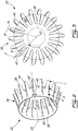
Fig. 3 is a rear view of the mixer ofFig. 2 ; -
Fig. 4 is a top tridimensional view of part of the mixer ofFig. 2 ; -
Fig. 5 shows in superposition three cross-sections of a same outer lobe within different planes defined along the length of the mixer ofFig. 2 ; -
Fig. 6 is a side, rear perspective view of part of the mixer ofFig. 2 ; -
Fig. 7 is a top tridimensional view of part of a mixer in accordance with another particular embodiment; -
Fig. 8 is a side, rear perspective view of part of a mixer in accordance with another particular embodiment; -
Fig. 9A is a tridimensional schematic representations of vortices in an outer lobe of a straight mixer; and -
Fig. 9B is a tridimensional schematic representation of vortices in an outer lobe of a mixer according to a particular embodiment. -
Fig.1 illustrates agas turbine engine 10 of a type preferably provided for use in subsonic flight, generally comprising in serial flow communication afan 12 through which ambient air is propelled, acompressor section 14 for pressurizing the air, acombustor 16 in which the compressed air is mixed with fuel and ignited for generating an annular stream of hot combustion gases, and aturbine section 18 for extracting energy from the combustion gases. - The
gas turbine engine 10 includes afirst casing 20 which encloses the turbo machinery of the engine, and a second,outer casing 22 extending outwardly of thefirst casing 20 such as to define anannular bypass passage 24 therebetween. The air propelled by thefan 12 is split into a first portion which flows around thefirst casing 20 within thebypass passage 24, and a second portion which flows through amain gas path 26 which is defined within thefirst casing 20 and allows the flow to circulate through themultistage compressor 14,combustor 16 andturbine section 18 as described above. - At the aft end of the
engine 10, anaxisymmetrical bullet 28 is centered on alongitudinal axis 30 of theengine 10 and defines an inner wall of themain gas path 26 so that the turbine exhaust gases flow therearound. Anannular mixer 32 surrounds at least a portion of thebullet 28, themixer 32 acting as a rearmost portion of the outer wall defining themain gas path 26 and a rearmost portion of the inner wall defining thebypass passage 24. The hot gases from themain gas path 26 and the cooler air from thebypass passage 24 are thus mixed together by themixer 32 at the exit thereof such as to produce an exhaust with a reduced temperature. - Referring to
Figs. 2-3 , themixer 32 has a centrallongitudinal axis 33 and includes anannular wall 34 defining anupstream end 36 of themixer 32 along which the flows from themain gas path 26 and from thebypass passage 24 are received, and adownstream end 38 where the two flows meet and are mixed together. Theannular wall 34 includes afrustoconical portion 40 extending from and defining theupstream end 36, thefrustoconical portion 40 having a diameter progressively reducing toward thedownstream end 38. Theannular wall 34 also defines a plurality of circumferentially distributed lobes extending rearwardly from thefrustoconical portion 40. The lobes include alternating inner andouter lobes outer lobes 44 extending into thebypass passage 24 and theinner lobes 42 extending into themain gas path 26. As such, theinner lobes 42 define troughs in thebypass passage 24 in between adjacent ones of theouter lobes 44, while theouter lobes 44 define troughs in themain gas path 26 in between adjacent ones of theinner lobes 42. In the embodiment shown, eachlobe rounded tip 47, and extends from thefrustoconical portion 40 to thedownstream end 38 of themixer 32. - The
present mixer 32 is configured to allow (e.g. maintain or increase) the swirl in the turbine exhaust flow for enhanced mixing. In a particular embodiment, themixer 32 allows for improved aerodynamic performance relative to a straight mixer design. - Referring to
Fig. 4 , eachinner lobe 42 defines animaginary valley line 43 extending substantially longitudinally through its radially innermost points. Eachouter lobe 44 defines animaginary crest line 45 extending longitudinally or substantially longitudinally through its radially outermost points. In a typical straight mixer, each crest line and each valley line extends longitudinally. In the embodiment shown inFig. 4 , thecrest lines 45 and, optionally, thevalley lines 43 are curved with respect to a circumferential direction of themixer 32; in other words, thecrest lines 45 and, optionally, thevalley lines 43, have a curved shape when viewed in a respective direction which in a conventional straight mixer would superpose thecrest line 45/valley line 43 with thelongitudinal axis 33. Thecrest lines 45 are curved such as to define a circumferential offset with respect to thelongitudinal axis 33 in the same direction as that of the swirl, as will be detailed further below. - In a particular embodiment, the path of the
curved crest lines 45 andvalley lines 43 are obtained from a straight mixer configuration through circumferentially twisting thecrest lines 45 andvalley lines 43 about thelongitudinal axis 33. The circumferential twist of thecrest lines 45 may be the same or different from that of thevalley lines 43. In another embodiment, the path of thecurved crest lines 45 is obtained from a straight mixer configuration through pivoting of eachcrest line 45 about a respective pivot point located on a circle extending through thevalley lines 43. Alternately, any other type of curvature that deflects thecrest lines 45 and optionally, thevalley lines 43 in the circumferential direction may be used. Thevalley lines 43 may be deflected in the same or in an opposite direction as that of thecrest lines 45. - The
crest lines 45 and, optionally, thevalley lines 43 may be deflected at a constant rate along the longitudinal direction of themixer 32, or alternately, the rate of deflection may vary along the longitudinal direction. - The
crest lines 45 and, optionally, thevalley lines 43 can be deflected along only a downstream portion thereof, such that theouter lobes 44 and, optionally, theinner lobes 42 extend straight from theupstream end 36 up to location intermediate the upstream anddownstream ends downstream end 38. In another embodiment, thecrest lines 45 and, optionally, thevalley lines 43 are deflected along their entire length. - Referring to
Fig. 5 , three (3) cross-sections of a sameouter lobe 44 are shown, with each cross-section being located in a respective plane extending perpendicularly to thelongitudinal axis 33, at the locations a, b, c shown inFig. 2 .Cross section 44c is located in a plane at thedownstream end 38 of themixer 32,cross-section 44a is located in a plane closer to theupstream end 36, andcross-section 44b is located in a plane between that ofcross-sections outer lobe 44 includes abase 46 which is defined adjacent thefrustoconical portion 40, at the upstream end of thecrest line 45. - At the
downstream end 38 of themixer 32, illustrated bycross-section 44c, thecrest line 45 of eachouter lobe 44 is circumferentially offset with respect to thebase 46. It can be seen that an imaginary radial tip line Tc extending from the centrallongitudinal axis 33 to thecrest line 45 is circumferentially offset from an imaginary radial base line B extending from the centrallongitudinal axis 33 to a midpoint of thebase 46. The direction of the circumferential offset Oc from the base line B to the tip line Tc corresponds to the direction of the swirl S of the turbine exhaust flow entering themixer 32. In a particular embodiment, the offset angle Oc at thedownstream end 38 is at most 5°. In a particular embodiment, the offset angle Oc at thedownstream end 38 is at most 2°. In a particular embodiment, the offset angle Oc at thedownstream end 38 end is at least 0.5°. - In the embodiment shown, the circumferential offset of the
outer lobes 44 becomes progressively more pronounced toward thedownstream end 38 of themixer 32. Accordingly, the offset angle Oa from the radial base line B to the radial tip line Ta of thecross-section 44a closest to theupstream end 36 is smaller than the offset angle Ob from the radial base line B to the radial tip line Tb of theintermediary cross-section 44b, which is smaller than the offset angle Oc at thedownstream end 38. - In the embodiment shown and with reference to
Fig. 2 , eachouter lobe 44 in cross-section defines an imaginary center line extending at equal distance from the wall portions defining theouter lobe 44, illustrated at C for thedownstream end 38 inFig. 2 . In the embodiment shown, it can be seen that the center line C at thedownstream end 38 is angled (i.e. extends at a non-zero angle) with respect to an imaginary radial line R extending from thelongitudinal axis 33 and intersecting the center line C at the center of thetip 47; theouter lobe 44 is thus tilted with respect to the radial direction R. In the embodiment shown, eachouter lobe 44 has a straight center line C and is symmetrical with respect thereto. Alternately, the center line C and wall portions forming theouter lobes 44 may be curved and/or theouter lobe 44 may be asymmetrical about the center line C. - Referring to
Fig. 6 , in a particular embodiment, the trailing edge junction of eachouter lobe 44 with the adjacentinner lobes 42 defines ascallop 48, from which extends a pointedtab 50. In another particular embodiment shown inFig. 8 , the trailing edge junction of eachouter lobe 44 with the adjacentinner lobes 42 defines only ascallop 148. Any other adequate trailing edge treatment may alternately be used, for example a tabbed trailing edge. -
Fig. 7 shows an alternate embodiment for themixer 132 where thecrest lines 145 are curved relative to the longitudinal direction and where thevalley lines 143 are straight. In a particular embodiment, thevalley lines 143 are coplanar with the longitudinal axis, such that theinner lobes 42 are straight and longitudinal. In a particular embodiment, the path of thecurved crest lines 145 is obtained through pivoting of eachcrest line 145 about a respective pivot point located on a circle extending through the valley lines 143. - In use, the turning of the
outer lobe 44 through circumferential deflection of thecrest line Fig. 9A , in a conventional mixer with straight longitudinal lobes, the mixing is achieved through radial vortices generated in the shear layer and pairs of counter rotating vortices generated by the core flow penetrating into the cold flow at the lobe crest and that are transported downstream symmetrically or substantially symmetrically (a small amount of residual swirl may prevent the flow from being exactly symmetrical). The centers 60, 60' of the pair of vortices are transported downstream symmetrically along apath 62 located at a same radial distance from thelongitudinal axis 33. - In a particular embodiment, and referring to
Fig. 9B , the offset of theouter lobes 44 changes the trajectory of the pairs of vortices such that the centers ofadjacent vortices 160, 160' migrate topaths 162 defined at different radii. Because of the shift in radii, the span of radius over which the vortices have an effect is increased, increasing mixing. In addition, the two adjacent vortices of consecutive lobes are also at different radii which increase their interaction resulting in more cold flow between consecutive lobes being involved in the mixing process. Finally, the interactions of the vortices with the shear layer formed by the mixer side walls result in the shear layer deforming and increasing its surface area, further increasing the mixing area. - Generally, turning the flow is known to increase pressure losses due to the resulting secondary flows generated. In a particular embodiment, the configuration offset outer lobes 44 (and optionally, offset inner lobes 42) result in an increase in the mixing downstream of the
mixer - In a particular embodiment and as mentioned above, the minimum turn or offset angle to turn the flow sufficiently to cause the radial migration is 0.5°. In a particular embodiment, the upper limit for the offset angle is determined such as to limit the pressure losses. In a particular embodiment, the maximum offset angle is 2°. In another particular embodiment, the maximum offset angle is 5°. An offset angle that is too high may lead to an increase in lossed in the mixer and nozzle high enough to reduce the resulting thrust coefficient, which may cause an increase in specific fuel consumption instead of the desired reduction. Losses in the mixer and nozzle may include bypass loss (loss incurred from the outer lobe leading edge to the mixer trailing edge), core loss (loss incurred from the inner lobe leading edge to the mixer trailing edge) and/or mixing pressure loss (loss incurred from the mixer trailing edge to the nozzle exit).
- In a particular embodiment, the improved mixing of the
mixer mixer mixer - In a particular embodiment, the
mixer mixer Fig. 1 ) leaving some residual swirl may thus be used upstream of themixer - A limiting factor of mixer design may be avoidance of hot gas impingement on a nozzle wall 21 (see
Fig. 1 ) downstream of the mixer, as nozzles are often made from composite material with temperature capabilities below the temperature of the hot gas. The degree of impingement is a function of the degree of penetration of the outer lobes into the cold flow. In a conventional straight mixer, the area of mixing may be increased by increasing penetration, but the hot gas impingement on the nozzle wall limits the possible increase in penetration and as such the possible performance improvement. In a particular embodiment, the offsetouter lobes 44 of themixer mixer longitudinal axis 33. - The above description is meant to be exemplary only, and one skilled in the art will recognize that changes may be made to the embodiments described without departing from the scope of the invention disclosed. Modifications which fall within the scope of the present invention will be apparent to those skilled in the art, in light of a review of this disclosure, and such modifications are intended to fall within the appended claims.
Claims (14)
- A gas turbine engine comprising:an annular bypass passage (24) for channelling air from a fan flow;a main gas path passage (26) for receiving a flow having a swirl component in a given direction; andan exhaust mixer (32) adapted to receive the flow from the main gas path passage (26) having the swirl component in the given direction, the exhaust mixer (32) comprising:
an annular wall (34) defining a central longitudinal axis (33), the annular wall (34) having opposed upstream and downstream ends (36, 38) and defining a plurality of circumferentially distributed alternating inner and outer lobes (42, 44), witheach inner lobe (42) protruding into the main gas path passage (26), andeach outer lobe (44) protruding into the annular bypass passage (24), each outer lobe (44) having a crest line (45) extending substantially longitudinally through each radially outermost point of the outer lobe (44) and a base (46) defined between spaced apart wall portions of the outer lobe (44) at an upstream end of the crest line (45), at least a downstream portion of the crest line (45) being curved with respect to a circumferential direction of the exhaust mixer (32), characterized in thatthe crest line (45) of each outer lobe (44) is curved such as to define a circumferential offset with respect to the longitudinal axis (33) in the same direction as that of the swirl component of the flow from the main gas path passage in order to maintain or increase the swirl in the turbine exhaust flow. - The gas turbine engine as defined in claim 1, wherein in a cross-section located at the downstream end, each outer lobe (44) defines a center line extending at equal distance from the spaced apart wall portions defining the outer lobe (44), the center line extending at a non-zero angle with respect to a radial line extending from the longitudinal axis (33) and intersecting the center line at the tip of the outer lobe (44).
- The gas turbine engine as defined in claim 2, wherein each outer lobe (44) is symmetrical about the center line at the downstream end.
- The gas turbine engine as defined in any preceding claim, wherein the circumferential offset between the base (46) and the downstream end is at most 5 degrees.
- The gas turbine engine as defined in any preceding claim, wherein the circumferential offset at the downstream end is at most 2 degrees.
- The gas turbine engine as defined in claim 4 or 5, wherein the circumferential offset at the downstream end is at least 0.5 degrees.
- The gas turbine engine as defined in any preceding claim, wherein each crest line (45) is curved along an entire length thereof.
- The gas turbine engine as defined in any preceding claim, wherein each inner lobe (42) defines a valley line (43) extending substantially longitudinally through each radially innermost point of the inner lobe (42), at least a downstream portion of the valley line (43) being curved with respect to the circumferential direction of the exhaust mixer (32).
- The gas turbine engine as defined in claim 8, wherein each crest line (45) and each valley line (43) are curved along an entire length thereof.
- The gas turbine engine as defined in any of claims 1 to 7, wherein each inner lobe (42) defines a valley line (43) extending substantially longitudinally through each radially innermost point of the inner lobe (42), each valley line (43) being coplanar with the longitudinal axis (43).
- The gas turbine engine as defined in any preceding claim, wherein a path of each crest line (45) corresponds to a circumferential twist about the central longitudinal axis (33).
- The gas turbine engine as defined in any preceding claim, wherein each inner lobe (42) defines a valley line (43) extending substantially longitudinally through each radially innermost point of the inner lobe, and wherein a path of each crest line (45) corresponds to a pivot about a respective pivot point located on a perimeter of a same imaginary circle extending through each valley line (43).
- A method of mixing the core flow and the bypass flow surrounding the core flow in the gas turbine engine as defined in any of the preceeding claims, the method comprising:circulating the core flow through the exhaust mixer (32) and the bypass flow around the exhaust mixer (32);generating pairs of counter rotating radial vortices (160, 160') within the core flow near a tip of the outer lobes (44); andwith the outer lobes (44), guiding a downstream transport of the vortices (160, 160') such that adjacent ones of the vortices in a same pair move along different paths defined at different radial distances from a longitudinal axis of the exhaust mixer (32).
- The method as defined in claim 13, further comprising, with the outer lobes (44), guiding the downstream transport of the vortices such that adjacent ones of the vortices in adjacent ones of the outer lobes move along paths defined at different radial distances from the longitudinal axis.
Applications Claiming Priority (1)
| Application Number | Priority Date | Filing Date | Title |
|---|---|---|---|
| US13/937,587 US11085333B2 (en) | 2013-07-09 | 2013-07-09 | Exhaust mixer with offset lobes |
Publications (2)
| Publication Number | Publication Date |
|---|---|
| EP2824308A1 EP2824308A1 (en) | 2015-01-14 |
| EP2824308B1 true EP2824308B1 (en) | 2018-12-26 |
Family
ID=51224676
Family Applications (1)
| Application Number | Title | Priority Date | Filing Date |
|---|---|---|---|
| EP14173655.3A Active EP2824308B1 (en) | 2013-07-09 | 2014-06-24 | Exhaust mixer with offset lobes |
Country Status (3)
| Country | Link |
|---|---|
| US (1) | US11085333B2 (en) |
| EP (1) | EP2824308B1 (en) |
| CA (1) | CA2851073C (en) |
Families Citing this family (11)
| Publication number | Priority date | Publication date | Assignee | Title |
|---|---|---|---|---|
| US10436149B2 (en) * | 2015-09-29 | 2019-10-08 | Pratt & Whitney Canada Corp. | Gas turbine engine exhaust mixer with lobes cross-over offset |
| US10738649B2 (en) | 2017-08-03 | 2020-08-11 | Rolls-Royce Corporation | Reinforced oxide-oxide ceramic matrix composite (CMC) component and method of making a reinforced oxide-oxide CMC component |
| US20200318495A1 (en) * | 2019-04-08 | 2020-10-08 | Pratt & Whitney Canada Corp. | Turbine exhaust case mixer |
| CN113047979A (en) * | 2021-04-01 | 2021-06-29 | 南昌航空大学 | Lobed wave crest for in-band beveling or fan-shaped treatment lobe nozzle |
| CN113074061A (en) * | 2021-04-01 | 2021-07-06 | 南昌航空大学 | Sawtooth wave crest spoiler for alternating lobe spray pipe |
| US20220325678A1 (en) * | 2021-04-08 | 2022-10-13 | Boom Technology, Inc. | Lobed mixer nozzles for supersonic and subsonic aircraft, and associated systems and methods |
| WO2022216468A1 (en) * | 2021-04-08 | 2022-10-13 | Boom Technology, Inc. | Lobed mixer nozzles for supersonic and subsonic aircraft, and associated systems and methods |
| CN113123898B (en) * | 2021-04-19 | 2022-06-07 | 中国人民解放军国防科技大学 | Supersonic flow mixing device based on jet flow disturbance at rear edge of partition plate |
| CN114412656B (en) * | 2022-01-25 | 2023-06-16 | 北京环境特性研究所 | Mixer for suppressing backward infrared radiation characteristic of exhaust system |
| US11828248B1 (en) | 2022-06-27 | 2023-11-28 | Pratt & Whitney Canada Corp. | Rotatably driven exhaust mixer |
| CN116378847B (en) * | 2023-04-10 | 2023-09-29 | 南京航空航天大学 | Single-drive lobe nozzle structure with heat transfer and structural reinforcement |
Family Cites Families (9)
| Publication number | Priority date | Publication date | Assignee | Title |
|---|---|---|---|---|
| US4045957A (en) | 1976-02-20 | 1977-09-06 | United Technologies Corporation | Combined guide vane and mixer for a gas turbine engine |
| DE60019264T2 (en) | 1999-01-04 | 2006-02-16 | Allison Advanced Development Co., Indianapolis | EXHAUST MIXING DEVICE AND DEVICE WITH SUCH A DEVICE |
| US7506501B2 (en) | 2004-12-01 | 2009-03-24 | Honeywell International Inc. | Compact mixer with trimmable open centerbody |
| US7389635B2 (en) * | 2004-12-01 | 2008-06-24 | Honeywell International Inc. | Twisted mixer with open center body |
| FR2896274B1 (en) | 2006-01-13 | 2008-04-18 | Snecma Sa | VARIABLE SECTION FLOW MIXER FOR DOUBLE TURBOREACTOR FLOW OF SUPERSONIC AIRPLANE |
| EP1870588B1 (en) * | 2006-06-19 | 2010-01-13 | Snecma | Mixer for double-flow turbomachine, and corresponding nozzle and turbomachine |
| FR2911922B1 (en) | 2007-01-26 | 2009-04-24 | Snecma Sa | VARIABLE SECTION FLOW MIXER FOR A DOUBLE FLOW OF A SUPERSONIC AIRCRAFT |
| US20100199626A1 (en) * | 2008-12-31 | 2010-08-12 | Benjamin Roland Harding | Turbine engine exhaust gas tube mixer |
| US8104260B2 (en) | 2009-05-22 | 2012-01-31 | Pratt & Whitney Canada Corp. | Deswirling exhaust mixer |
-
2013
- 2013-07-09 US US13/937,587 patent/US11085333B2/en active Active
-
2014
- 2014-05-02 CA CA2851073A patent/CA2851073C/en active Active
- 2014-06-24 EP EP14173655.3A patent/EP2824308B1/en active Active
Non-Patent Citations (1)
| Title |
|---|
| None * |
Also Published As
| Publication number | Publication date |
|---|---|
| US11085333B2 (en) | 2021-08-10 |
| CA2851073C (en) | 2022-08-09 |
| CA2851073A1 (en) | 2015-01-09 |
| US20150013341A1 (en) | 2015-01-15 |
| EP2824308A1 (en) | 2015-01-14 |
Similar Documents
| Publication | Publication Date | Title |
|---|---|---|
| EP2824308B1 (en) | Exhaust mixer with offset lobes | |
| EP2383455B1 (en) | Gas turbine engine exhaust mixer | |
| US6314721B1 (en) | Tabbed nozzle for jet noise suppression | |
| EP2258925A2 (en) | Cooling arrangements | |
| US20190106991A1 (en) | Engine component | |
| US20100293958A1 (en) | Deswirling exhaust mixer | |
| EP3348908B1 (en) | Gas turbine fuel injector | |
| US10024169B2 (en) | Engine component | |
| EP2660424A1 (en) | Inter-turbine ducts with variable area ratios | |
| US10267161B2 (en) | Gas turbine engine with fillet film holes | |
| US20160326983A1 (en) | Integrated tec/mixer strut axial position | |
| US20200025132A1 (en) | Gas turbine engine ejector | |
| US8984890B2 (en) | Turbofan engine mixer assembly | |
| EP3181880B1 (en) | Gas turbine engine exhaust mixer with lobes cross-over offset | |
| EP4400708A1 (en) | Exhaust mixer with protrusions | |
| US20190301488A1 (en) | Gas path duct for a gas turbine engine | |
| EP4400707A1 (en) | Exhaust mixer with protrusions | |
| EP3150836A1 (en) | Integrated tec/mixer strut axial position | |
| US11965653B2 (en) | Dilution air inlets with notched tip and slotted tail for combustor | |
| US20240229740A1 (en) | Exhaust mixer with protrusions | |
| US20180216475A1 (en) | Component for a gas turbine engine | |
| CN117869012A (en) | Gas turbine exhaust nozzle noise reduction | |
| WO2017023331A1 (en) | Ducting arrangement for directing combustion gas |
Legal Events
| Date | Code | Title | Description |
|---|---|---|---|
| 17P | Request for examination filed |
Effective date: 20140624 |
|
| AK | Designated contracting states |
Kind code of ref document: A1 Designated state(s): AL AT BE BG CH CY CZ DE DK EE ES FI FR GB GR HR HU IE IS IT LI LT LU LV MC MK MT NL NO PL PT RO RS SE SI SK SM TR |
|
| AX | Request for extension of the european patent |
Extension state: BA ME |
|
| PUAI | Public reference made under article 153(3) epc to a published international application that has entered the european phase |
Free format text: ORIGINAL CODE: 0009012 |
|
| R17P | Request for examination filed (corrected) |
Effective date: 20150714 |
|
| RBV | Designated contracting states (corrected) |
Designated state(s): AL AT BE BG CH CY CZ DE DK EE ES FI FR GB GR HR HU IE IS IT LI LT LU LV MC MK MT NL NO PL PT RO RS SE SI SK SM TR |
|
| 17Q | First examination report despatched |
Effective date: 20160302 |
|
| GRAP | Despatch of communication of intention to grant a patent |
Free format text: ORIGINAL CODE: EPIDOSNIGR1 |
|
| STAA | Information on the status of an ep patent application or granted ep patent |
Free format text: STATUS: GRANT OF PATENT IS INTENDED |
|
| INTG | Intention to grant announced |
Effective date: 20180628 |
|
| GRAS | Grant fee paid |
Free format text: ORIGINAL CODE: EPIDOSNIGR3 |
|
| GRAA | (expected) grant |
Free format text: ORIGINAL CODE: 0009210 |
|
| STAA | Information on the status of an ep patent application or granted ep patent |
Free format text: STATUS: THE PATENT HAS BEEN GRANTED |
|
| AK | Designated contracting states |
Kind code of ref document: B1 Designated state(s): AL AT BE BG CH CY CZ DE DK EE ES FI FR GB GR HR HU IE IS IT LI LT LU LV MC MK MT NL NO PL PT RO RS SE SI SK SM TR |
|
| REG | Reference to a national code |
Ref country code: GB Ref legal event code: FG4D |
|
| REG | Reference to a national code |
Ref country code: CH Ref legal event code: EP |
|
| REG | Reference to a national code |
Ref country code: AT Ref legal event code: REF Ref document number: 1081760 Country of ref document: AT Kind code of ref document: T Effective date: 20190115 |
|
| REG | Reference to a national code |
Ref country code: DE Ref legal event code: R096 Ref document number: 602014038498 Country of ref document: DE |
|
| REG | Reference to a national code |
Ref country code: IE Ref legal event code: FG4D |
|
| PG25 | Lapsed in a contracting state [announced via postgrant information from national office to epo] |
Ref country code: NO Free format text: LAPSE BECAUSE OF FAILURE TO SUBMIT A TRANSLATION OF THE DESCRIPTION OR TO PAY THE FEE WITHIN THE PRESCRIBED TIME-LIMIT Effective date: 20190326 Ref country code: HR Free format text: LAPSE BECAUSE OF FAILURE TO SUBMIT A TRANSLATION OF THE DESCRIPTION OR TO PAY THE FEE WITHIN THE PRESCRIBED TIME-LIMIT Effective date: 20181226 Ref country code: BG Free format text: LAPSE BECAUSE OF FAILURE TO SUBMIT A TRANSLATION OF THE DESCRIPTION OR TO PAY THE FEE WITHIN THE PRESCRIBED TIME-LIMIT Effective date: 20190326 Ref country code: LT Free format text: LAPSE BECAUSE OF FAILURE TO SUBMIT A TRANSLATION OF THE DESCRIPTION OR TO PAY THE FEE WITHIN THE PRESCRIBED TIME-LIMIT Effective date: 20181226 Ref country code: FI Free format text: LAPSE BECAUSE OF FAILURE TO SUBMIT A TRANSLATION OF THE DESCRIPTION OR TO PAY THE FEE WITHIN THE PRESCRIBED TIME-LIMIT Effective date: 20181226 Ref country code: LV Free format text: LAPSE BECAUSE OF FAILURE TO SUBMIT A TRANSLATION OF THE DESCRIPTION OR TO PAY THE FEE WITHIN THE PRESCRIBED TIME-LIMIT Effective date: 20181226 |
|
| REG | Reference to a national code |
Ref country code: NL Ref legal event code: MP Effective date: 20181226 |
|
| REG | Reference to a national code |
Ref country code: LT Ref legal event code: MG4D |
|
| PG25 | Lapsed in a contracting state [announced via postgrant information from national office to epo] |
Ref country code: AL Free format text: LAPSE BECAUSE OF FAILURE TO SUBMIT A TRANSLATION OF THE DESCRIPTION OR TO PAY THE FEE WITHIN THE PRESCRIBED TIME-LIMIT Effective date: 20181226 Ref country code: SE Free format text: LAPSE BECAUSE OF FAILURE TO SUBMIT A TRANSLATION OF THE DESCRIPTION OR TO PAY THE FEE WITHIN THE PRESCRIBED TIME-LIMIT Effective date: 20181226 Ref country code: RS Free format text: LAPSE BECAUSE OF FAILURE TO SUBMIT A TRANSLATION OF THE DESCRIPTION OR TO PAY THE FEE WITHIN THE PRESCRIBED TIME-LIMIT Effective date: 20181226 Ref country code: GR Free format text: LAPSE BECAUSE OF FAILURE TO SUBMIT A TRANSLATION OF THE DESCRIPTION OR TO PAY THE FEE WITHIN THE PRESCRIBED TIME-LIMIT Effective date: 20190327 |
|
| REG | Reference to a national code |
Ref country code: AT Ref legal event code: MK05 Ref document number: 1081760 Country of ref document: AT Kind code of ref document: T Effective date: 20181226 |
|
| PG25 | Lapsed in a contracting state [announced via postgrant information from national office to epo] |
Ref country code: NL Free format text: LAPSE BECAUSE OF FAILURE TO SUBMIT A TRANSLATION OF THE DESCRIPTION OR TO PAY THE FEE WITHIN THE PRESCRIBED TIME-LIMIT Effective date: 20181226 |
|
| PG25 | Lapsed in a contracting state [announced via postgrant information from national office to epo] |
Ref country code: PT Free format text: LAPSE BECAUSE OF FAILURE TO SUBMIT A TRANSLATION OF THE DESCRIPTION OR TO PAY THE FEE WITHIN THE PRESCRIBED TIME-LIMIT Effective date: 20190426 Ref country code: CZ Free format text: LAPSE BECAUSE OF FAILURE TO SUBMIT A TRANSLATION OF THE DESCRIPTION OR TO PAY THE FEE WITHIN THE PRESCRIBED TIME-LIMIT Effective date: 20181226 Ref country code: IT Free format text: LAPSE BECAUSE OF FAILURE TO SUBMIT A TRANSLATION OF THE DESCRIPTION OR TO PAY THE FEE WITHIN THE PRESCRIBED TIME-LIMIT Effective date: 20181226 Ref country code: PL Free format text: LAPSE BECAUSE OF FAILURE TO SUBMIT A TRANSLATION OF THE DESCRIPTION OR TO PAY THE FEE WITHIN THE PRESCRIBED TIME-LIMIT Effective date: 20181226 Ref country code: ES Free format text: LAPSE BECAUSE OF FAILURE TO SUBMIT A TRANSLATION OF THE DESCRIPTION OR TO PAY THE FEE WITHIN THE PRESCRIBED TIME-LIMIT Effective date: 20181226 |
|
| PGFP | Annual fee paid to national office [announced via postgrant information from national office to epo] |
Ref country code: DE Payment date: 20190521 Year of fee payment: 6 |
|
| PG25 | Lapsed in a contracting state [announced via postgrant information from national office to epo] |
Ref country code: SM Free format text: LAPSE BECAUSE OF FAILURE TO SUBMIT A TRANSLATION OF THE DESCRIPTION OR TO PAY THE FEE WITHIN THE PRESCRIBED TIME-LIMIT Effective date: 20181226 Ref country code: EE Free format text: LAPSE BECAUSE OF FAILURE TO SUBMIT A TRANSLATION OF THE DESCRIPTION OR TO PAY THE FEE WITHIN THE PRESCRIBED TIME-LIMIT Effective date: 20181226 Ref country code: RO Free format text: LAPSE BECAUSE OF FAILURE TO SUBMIT A TRANSLATION OF THE DESCRIPTION OR TO PAY THE FEE WITHIN THE PRESCRIBED TIME-LIMIT Effective date: 20181226 Ref country code: IS Free format text: LAPSE BECAUSE OF FAILURE TO SUBMIT A TRANSLATION OF THE DESCRIPTION OR TO PAY THE FEE WITHIN THE PRESCRIBED TIME-LIMIT Effective date: 20190426 Ref country code: SK Free format text: LAPSE BECAUSE OF FAILURE TO SUBMIT A TRANSLATION OF THE DESCRIPTION OR TO PAY THE FEE WITHIN THE PRESCRIBED TIME-LIMIT Effective date: 20181226 |
|
| REG | Reference to a national code |
Ref country code: DE Ref legal event code: R097 Ref document number: 602014038498 Country of ref document: DE |
|
| PG25 | Lapsed in a contracting state [announced via postgrant information from national office to epo] |
Ref country code: DK Free format text: LAPSE BECAUSE OF FAILURE TO SUBMIT A TRANSLATION OF THE DESCRIPTION OR TO PAY THE FEE WITHIN THE PRESCRIBED TIME-LIMIT Effective date: 20181226 Ref country code: AT Free format text: LAPSE BECAUSE OF FAILURE TO SUBMIT A TRANSLATION OF THE DESCRIPTION OR TO PAY THE FEE WITHIN THE PRESCRIBED TIME-LIMIT Effective date: 20181226 |
|
| PLBE | No opposition filed within time limit |
Free format text: ORIGINAL CODE: 0009261 |
|
| STAA | Information on the status of an ep patent application or granted ep patent |
Free format text: STATUS: NO OPPOSITION FILED WITHIN TIME LIMIT |
|
| 26N | No opposition filed |
Effective date: 20190927 |
|
| PG25 | Lapsed in a contracting state [announced via postgrant information from national office to epo] |
Ref country code: MC Free format text: LAPSE BECAUSE OF FAILURE TO SUBMIT A TRANSLATION OF THE DESCRIPTION OR TO PAY THE FEE WITHIN THE PRESCRIBED TIME-LIMIT Effective date: 20181226 |
|
| REG | Reference to a national code |
Ref country code: CH Ref legal event code: PL |
|
| PG25 | Lapsed in a contracting state [announced via postgrant information from national office to epo] |
Ref country code: SI Free format text: LAPSE BECAUSE OF FAILURE TO SUBMIT A TRANSLATION OF THE DESCRIPTION OR TO PAY THE FEE WITHIN THE PRESCRIBED TIME-LIMIT Effective date: 20181226 |
|
| REG | Reference to a national code |
Ref country code: BE Ref legal event code: MM Effective date: 20190630 |
|
| PG25 | Lapsed in a contracting state [announced via postgrant information from national office to epo] |
Ref country code: TR Free format text: LAPSE BECAUSE OF FAILURE TO SUBMIT A TRANSLATION OF THE DESCRIPTION OR TO PAY THE FEE WITHIN THE PRESCRIBED TIME-LIMIT Effective date: 20181226 |
|
| PG25 | Lapsed in a contracting state [announced via postgrant information from national office to epo] |
Ref country code: IE Free format text: LAPSE BECAUSE OF NON-PAYMENT OF DUE FEES Effective date: 20190624 |
|
| PG25 | Lapsed in a contracting state [announced via postgrant information from national office to epo] |
Ref country code: LU Free format text: LAPSE BECAUSE OF NON-PAYMENT OF DUE FEES Effective date: 20190624 Ref country code: LI Free format text: LAPSE BECAUSE OF NON-PAYMENT OF DUE FEES Effective date: 20190630 Ref country code: CH Free format text: LAPSE BECAUSE OF NON-PAYMENT OF DUE FEES Effective date: 20190630 Ref country code: BE Free format text: LAPSE BECAUSE OF NON-PAYMENT OF DUE FEES Effective date: 20190630 |
|
| REG | Reference to a national code |
Ref country code: DE Ref legal event code: R119 Ref document number: 602014038498 Country of ref document: DE |
|
| PG25 | Lapsed in a contracting state [announced via postgrant information from national office to epo] |
Ref country code: DE Free format text: LAPSE BECAUSE OF NON-PAYMENT OF DUE FEES Effective date: 20210101 Ref country code: CY Free format text: LAPSE BECAUSE OF FAILURE TO SUBMIT A TRANSLATION OF THE DESCRIPTION OR TO PAY THE FEE WITHIN THE PRESCRIBED TIME-LIMIT Effective date: 20181226 |
|
| PG25 | Lapsed in a contracting state [announced via postgrant information from national office to epo] |
Ref country code: HU Free format text: LAPSE BECAUSE OF FAILURE TO SUBMIT A TRANSLATION OF THE DESCRIPTION OR TO PAY THE FEE WITHIN THE PRESCRIBED TIME-LIMIT; INVALID AB INITIO Effective date: 20140624 Ref country code: MT Free format text: LAPSE BECAUSE OF FAILURE TO SUBMIT A TRANSLATION OF THE DESCRIPTION OR TO PAY THE FEE WITHIN THE PRESCRIBED TIME-LIMIT Effective date: 20181226 |
|
| PG25 | Lapsed in a contracting state [announced via postgrant information from national office to epo] |
Ref country code: MK Free format text: LAPSE BECAUSE OF FAILURE TO SUBMIT A TRANSLATION OF THE DESCRIPTION OR TO PAY THE FEE WITHIN THE PRESCRIBED TIME-LIMIT Effective date: 20181226 |
|
| P01 | Opt-out of the competence of the unified patent court (upc) registered |
Effective date: 20230530 |
|
| PGFP | Annual fee paid to national office [announced via postgrant information from national office to epo] |
Ref country code: GB Payment date: 20240521 Year of fee payment: 11 |
|
| PGFP | Annual fee paid to national office [announced via postgrant information from national office to epo] |
Ref country code: FR Payment date: 20240521 Year of fee payment: 11 |