EP1104743B1 - Doppelstöckiger Satellitenaussetzer mit freitragenden Bühnen - Google Patents
Doppelstöckiger Satellitenaussetzer mit freitragenden Bühnen Download PDFInfo
- Publication number
- EP1104743B1 EP1104743B1 EP00204260A EP00204260A EP1104743B1 EP 1104743 B1 EP1104743 B1 EP 1104743B1 EP 00204260 A EP00204260 A EP 00204260A EP 00204260 A EP00204260 A EP 00204260A EP 1104743 B1 EP1104743 B1 EP 1104743B1
- Authority
- EP
- European Patent Office
- Prior art keywords
- platform
- post
- support
- satellites
- platform assembly
- Prior art date
- Legal status (The legal status is an assumption and is not a legal conclusion. Google has not performed a legal analysis and makes no representation as to the accuracy of the status listed.)
- Expired - Lifetime
Links
Images






Classifications
-
- B—PERFORMING OPERATIONS; TRANSPORTING
- B64—AIRCRAFT; AVIATION; COSMONAUTICS
- B64G—COSMONAUTICS; VEHICLES OR EQUIPMENT THEREFOR
- B64G1/00—Cosmonautic vehicles
- B64G1/002—Launch systems
-
- B—PERFORMING OPERATIONS; TRANSPORTING
- B64—AIRCRAFT; AVIATION; COSMONAUTICS
- B64G—COSMONAUTICS; VEHICLES OR EQUIPMENT THEREFOR
- B64G1/00—Cosmonautic vehicles
-
- B—PERFORMING OPERATIONS; TRANSPORTING
- B64—AIRCRAFT; AVIATION; COSMONAUTICS
- B64G—COSMONAUTICS; VEHICLES OR EQUIPMENT THEREFOR
- B64G1/00—Cosmonautic vehicles
- B64G1/22—Parts of, or equipment specially adapted for fitting in or to, cosmonautic vehicles
- B64G1/64—Systems for coupling or separating cosmonautic vehicles or parts thereof, e.g. docking arrangements
- B64G1/641—Interstage or payload connectors
- B64G1/643—Interstage or payload connectors for arranging multiple satellites in a single launcher
-
- B—PERFORMING OPERATIONS; TRANSPORTING
- B64—AIRCRAFT; AVIATION; COSMONAUTICS
- B64G—COSMONAUTICS; VEHICLES OR EQUIPMENT THEREFOR
- B64G1/00—Cosmonautic vehicles
- B64G1/22—Parts of, or equipment specially adapted for fitting in or to, cosmonautic vehicles
- B64G1/64—Systems for coupling or separating cosmonautic vehicles or parts thereof, e.g. docking arrangements
- B64G1/641—Interstage or payload connectors
- B64G1/643—Interstage or payload connectors for arranging multiple satellites in a single launcher
- B64G1/644—Interstage or payload connectors for arranging multiple satellites in a single launcher arranged for independent deployment
-
- B—PERFORMING OPERATIONS; TRANSPORTING
- B64—AIRCRAFT; AVIATION; COSMONAUTICS
- B64G—COSMONAUTICS; VEHICLES OR EQUIPMENT THEREFOR
- B64G1/00—Cosmonautic vehicles
- B64G1/22—Parts of, or equipment specially adapted for fitting in or to, cosmonautic vehicles
- B64G1/64—Systems for coupling or separating cosmonautic vehicles or parts thereof, e.g. docking arrangements
- B64G1/645—Separators
-
- B—PERFORMING OPERATIONS; TRANSPORTING
- B64—AIRCRAFT; AVIATION; COSMONAUTICS
- B64G—COSMONAUTICS; VEHICLES OR EQUIPMENT THEREFOR
- B64G1/00—Cosmonautic vehicles
- B64G1/10—Artificial satellites; Systems of such satellites; Interplanetary vehicles
- B64G1/1085—Swarms and constellations
Definitions
- This invention relates to spacecraft dispensers, and more particularly to a satellite dispenser having a cantilever, bi-level platform configuration which allows the satellites to be deployed to be supported at a lower surface of each, while significantly reducing the overall weight of the dispenser without reducing its payload capability.
- Space vehicle dispensers are used to deploy a plurality of satellites (typically between 4-12 satellites) into low earth orbit (LEO) during a launch vehicle (LV) mission.
- LEO low earth orbit
- the dispenser provides the structural link between the satellites and the launch vehicle.
- the dispenser be constructed so as to be as lightweight as possible without sacrificing structural strength, and while being able to support a plurality of independently deployable satellites thereon.
- One prior dispenser approach is the "Dual Manifest using external structure.”
- the payload fairing is split into two payload modules: an upper module and a lower module.
- the payload fairing may be divided into a soft 9.15 meter tall lower module and a 13.725 meter (45 ft) tall upper module.
- Each module has its own dispenser which includes a horizontal platform for supporting a plurality of satellites thereon.
- the upper payload fairing is jettisoned; however, the lower payload module goes into orbit.
- the penalty for carrying the extra payload module weight (i.e., the weight associated with the fairing of the lower payload module) to low earth orbit is less payload which can be carried into orbit.
- the lower payload module fairing debris stays in orbit for approximately 9-12 months, which can raise the risk of damage to one or more of the deployed satellites.
- US-A-3 380 687 discloses a space vehicle dispenser apparatus for supporting a plurality of independently deployable spacecraft in a dual platform configuration to permit jettisoning of a full fairing of a space vehicle during ascent of the space vehicle said apparatus comprising:
- the post of this known apparatus supports the first platform assembly as well as the second platform assembly, which increases weight of the structure and therefore the maximum payload is reduced.
- the present invention relates to a cantilever, bi-level platform satellite dispenser apparatus and method which obviates the need for internal or external support structure to be used with the dispenser in accordance with claims 1 and 8, respectively.
- the dispenser generally comprises a lower platform assembly having a center post projecting therefrom and an upper platform assembly secured to a portion of the center post.
- the upper platform assembly is secured to an upper terminal end of the center post.
- a first subplurality of satellites typically between 2-6 satellites, can be supported on the lower platform assembly and without assistance from the center post.
- An additional subplurality of between about 2-6 satellites can also be supported on the upper platform assembly, also without assistance of the center post.
- Each subplurality of satellites is supported on its respective platform in a "cantilever" fashion offset from the longitudinal axis of the center post.
- This arrangement together with the manufacturing techniques used to manufacture the components of the dispenser, provides for minimum structural weight of the dispenser while inherently providing a design that allows jettisoning of the entire fairing of the launch vehicle during launch vehicle ascent.
- the lower platform assembly generally comprises a lower platform member disposed on an edge of a lower outer cone.
- the terminal end of the center post opposite to the end supporting the upper platform assembly is secured to the lower platform member, which is in turn supported by at least one of the lower inner cone or lower outer cone.
- Outermost edges of each of the lower inner and outer cones are secured to a base ring, which is used to support the entire dispenser apparatus on a surface of a portion of the launch vehicle.
- the upper platform assembly is somewhat similar to the lower platform assembly in construction and includes an upper ring, a support cone and an upper platform member.
- the upper platform member is secured to the upper support cone adjacent a terminal edge of the upper support cone, while an opposite terminal edge of the upper support cone is secured to the upper ring.
- the upper ring is in turn secured to a terminal end of the center post opposite to the end that is secured to the lower platform assembly.
- the upper platform assembly is spaced apart elevationally from the lower platform assembly without requiring a portion of the center post to extend outwardly of the upper platform member.
- no separate support structure, either internal or external to the fairing is employed. This weight savings in turn allows heavier payloads to be carried by the launch vehicle. This, in turn, contributes to more cost efficient operation of the launch vehicle.
- each of the upper and lower platform members also includes a plurality of openings intended to allow access to conventional separation assemblies.
- the separation assemblies are used to secure a plurality of satellites on each platform member so that the satellites can be readily deployed at the appropriate time during ascent of the launch vehicle.
- the preferred embodiments thus provide a lightweight spacecraft dispenser apparatus which allows the jettisoning of maximum fairing weight during launch vehicle ascent.
- the preferred embodiments of the dispenser apparatus of the present invention may further be assembled using widely available construction materials and conventional construction techniques.
- the dispenser apparatus 10 generally comprises a lower platform assembly 12 and an elevationally spaced apart upper platform assembly 14. Mounted on the lower platform assembly 12 may be anywhere from about 1-6 or more independently deployable spacecraft in the form of satellites 16. Similarly, mounted on the upper platform assembly 14 is also a plurality of between about 1-6 or more additional, independently deployable satellites 16. The full weight of each satellite 16 is supported by its associated platform assembly 12 or 14. The entire dispenser apparatus 10 may be enclosed within a fairing 18 which can be jettisoned at a desired time during the ascent of a launch vehicle 20 upon which the entire dispenser apparatus 10 and fairing 18 are mounted.
- the lower platform assembly 12 generally comprises a lower outer support cone 22, a lower inner support cone 24 disposed within the interior area of outer cone 22, a base ring 26 and a lower platform member 28. Projecting through a coaxially disposed opening 30 in the lower platform member 28 is an elongated center post 32. A plurality of openings 34 in the lower platform member 28 further enable access to conventional separation assemblies (not shown) which assist in deploying each of the satellites 16 at the proper time during ascent of the launch vehicle 20.
- the upper platform assembly 14 is secured at an upper terminal end 32a of the center post 32.
- the upper platform assembly 14 generally includes an upper ring 36, an upper cone 38 and an upper platform member 40.
- the upper platform member 40 also includes a plurality of openings 42 for enabling access to an additional plurality of conventional separation assemblies (not shown) which assist in independently deploying the satellites 16 secured to the upper platform member 40.
- the satellites 16 are supported at positions exteriorly of the center post 32 and therefore offset from the longitudinal axis of the center post 32 in a "cantilever" fashion. Using a relatively narrow center post 32 and supporting the satellites 16 as shown allows the weight of the center post 32 to be reduced significantly.
- Previous dispenser systems have incorporated large diameter posts and disposed the satellites being carried on the lower level platform within the interior of the center post. This significantly increases the weight and cost of the center post component and further restricts the size and arrangement of the satellites being supported on the lower platform level, in addition to significantly impeding access to the lower level satellites.
- the dispenser apparatus 10 permits substantially full access to the satellites 16 even after they are mounted on their associated platform assemblies 12 and 14.
- the dispenser apparatus 10 is intended to be of suitable dimensions to enable it to support preferably at least about 1-6 satellites 16 on the upper platform assembly 14 and at least an additional 1-6 satellites 16 on the lower platform assembly 12. Accordingly, the diameter of each platform member 28 and 40 is specifically suited to the number of satellites that need to be supported thereon. Additionally, the overall length of the center post 32 may vary considerably depending upon the height of the satellites 16 being supported on the lower platform assembly 12.
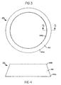
- the lower outer cone 22 is preferably a single piece component formed by a continuous, circular side wall 44, and preferably formed of sandwich composite construction.
- the circular side wall 44 has a lower edge 44a and an upper edge 44b. It will be appreciated, however, that the degree of taper could vary depending upon the requirements of a specific application.
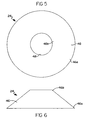
- the lower inner cone 24 can be seen.
- This cone is also formed as a single piece component from a continuous sidewall portion 46.
- the sidewall portion 46 forms a diameter at lower portion 46a which is slightly smaller than the diameter of the lower edge 44a of the lower outer cone 22.
- An opening 48 is formed at an upper portion 46b of the wall portion 46 which is preferably just slightly larger in diameter than the outer diameter of the center post 32.
- the wall portion 46 further includes a taper which is preferably between about 30 - 60° from the vertical. Again, it will be appreciated that the precise degree of this taper is not critical to the functioning of the lower inner cone 24.
- This component includes a generally planar surface 50 formed in two pieces and coupled by splice elements 50a.
- a central opening 52 is included and is suitably large to enable the center post 32 to project therethrough.
- the lower platform member 28 can also be seen to include an inner flange 54 angled normal to the planar surface 50, an outwardly angled intermediate flange 55, an outwardly angled outer annular flange 60, and an angled flange 59 extending normal to the planar surface 50.
- a plurality of structural webs 56 and 58 cooperatively help to provide structural strength and rigidity thereto.
- the annular outer flange 60 intersects the webbing 58 and further reinforces the platform 28 at the areas immediately adjacent the opening 52.
- the outer flange also forms a means by which the upper edge 44b of the lower outer cone can secure to the upper platform member 28.
- the lower platform member 28 is preferably formed by machining out of aluminum or another suitably strong, lightweight material.
- a single piece planar surface 50 could potentially be employed, but it is anticipated that for ease of manufacturing a two piece configuration will be most preferred.
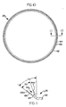
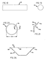
- the base ring 26 is preferably machined from aluminum or another suitably lightweight and structurally strong material and includes a lower flange portion 62 which is integrally formed with an outer lip 64 and an inner lip 66.
- the outer lip 64 and inner lip 66 cooperatively form an annular, V-shaped groove 68 around the entire circumference of the base ring 26.
- the angle of the outer lip 64 as indicated by arrow 70, preferably matches the taper of the lower outer cone 22.
- the relief portion 64a of the outer lip 64 is preferably just slightly smaller in diameter than that of the lower edge 44a of the lower outer cone 22. In this manner, the lower edge 44a may be disposed against the relief portion 64a and attached thereto.
- the angle of the inner lip 66 as indicated by arrow 72, preferably matches the degree of taper of the lower inner cone 24, and its diameter is just slightly smaller than the diameter of the lower edge 46a of the lower inner cone 24 such that the lower edge 46a thereof may be inserted over the relief portion 66a.
- the lower inner cone 24 and the lower outer cone 22 are preferably secured to the relief portions 64 and 66 by double lap splices utilizing splice elements 64b and 64c and fasteners 65. It will be appreciated, however, that other suitable forms of attachment could also be used.
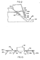
- center post 32 may be modified to provide even greater structural strength.
- the length of the center cone 32 could be extended slightly and the lower edge 32b thereof attached via a splice element 33 to the inner cone 24, as shown in Figure 14.
- the center post 32 could be formed as a filament wound component with an integrally formed, outwardly flaring lower portion 32' that functions in place of the inner cone 24, as shown in simplified form in Figure 15. These arrangements would even further increase the load carrying capability of the center post 32.
- the upper support cone 38 is also preferably formed as a single piece component from sandwich composite construction and forms a frustoconical-shaped cone.
- a continuous wall portion 74 defines an upper edge 74a and an opening 77c at a lower edge 74b of the wall portion 74.
- the degree of taper of the wall portion 74 may also vary considerably, but is preferably in the range of about 30 - 60° from the vertical.
- the center post 32 is shown in greater detail.
- the center post 32 is preferably of solid graphite epoxy construction and forms an extremely rigid, structurally strong and yet lightweight component.
- the thickness of the material forming the center post 32 may vary considerably, but in one preferred embodiment is preferably between about 1.22 - 2.14m (48 - 84 moles).
- the overall length of the center post 32 may also vary considerably depending upon the configuration and overall dimensions of the satellites 16 being supported on the dispenser apparatus 10.
- the upper support ring 36 is preferably machined out of a solid piece of aluminum or other structurally strong yet lightweight material.
- the upper support ring 36 includes a base portion 75 and an angled flange 76.
- the flange 76 has a relief portion 78 and a leg 76a.
- the diameter of the opening formed by the base portion 75, as indicated by dimensional arrow 81 in Figure 20, is preferably just slightly larger than the outer diameter of the center post 32 such that the center post can extend therethrough.
- the angle of the flange 76 preferably matches the angle of the upper support cone 38 such that the edge portion 74b of the upper support cone 38 can rest flush in the relief portion 78.
- the upper cone 38 is preferably secured to the upper support ring 36 by a double lap splice with a plurality of splice elements 79 and fasteners 79a circumferentially around flange 76.
- the base portion 75 is secured with fastening elements 75a to the center post 32.
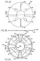
- the upper platform member 40 includes splice components 82 for securing the two halves which comprise the upper platform member 40 together to form a structurally strong and rigid component.
- a coaxial opening 84 is also defined which is preferably just slightly larger than the outer diameter of the center post 32.
- the upper platform member 40 also includes an outer annular flange 86 and an inner annular flange 88. With specific reference to Figure 24, a plurality of support webs 90 are formed adjacent the access openings 42 to provide further structural strength to these areas.
- a plurality of radially outwardly extending support webs 92 are formed to help provide additional structural strength to the upper platform member 40 at the areas where portions of the satellites 16 are expected to rest once mounted on the upper platform member 40.
- the upper platform member 40 is preferably machined from aluminum or another lightweight yet structurally strong material.
- the upper platform member 40 may also be formed as a single piece component from a single piece of aluminum, thus obviating the need for splice elements 82. It is expected, however, that in most instances it will be easier to manufacture the member 40 from two pieces of aluminum rather than a single piece.
- the upper platform member 40 can be seen attached to the upper cone 38.
- the upper platform member 40 is secured to edge 74a of the upper cone 38 by suitable fasteners (not shown) such that the edge 74a fits against the outer annular flange 86.
- the dispenser apparatus 10 forms a means by which a relatively large plurality of independently deployable satellites can be supported in a manner minimizing the overall weight of the dispenser.
- the dispenser apparatus 10 thus allows a greater payload capability for dual platform type support arrangements than previously developed dispensers, which require additional support structure (either internal of or external to the fairing) to support the payload in a dual platform configuration.
- the full weight of each of the satellites 16 is supported by its associated platform assembly 12 or 14.
- the dispenser apparatus 10 is significantly lighter in weight than previous dispenser designs and, importantly, permits substantially unimpeded access to the satellites 16 after same are secured to the dispenser 10.
- the dispenser apparatus 10 can further be manufactured from widely available materials using readily available construction techniques.
- the dual platform arrangement implemented by the dispenser 10 enables the entire fairing 18 to be jettisoned at the appropriate time during ascent of the launch vehicle 20 to thus maximize the amount of payload that may be placed into low earth orbit. Since no portion of the fairing 18 is carried into low earth orbit, the likelihood of any damage by orbital debris to the satellites 16, once deployed, is eliminated.
Landscapes
- Engineering & Computer Science (AREA)
- Remote Sensing (AREA)
- Aviation & Aerospace Engineering (AREA)
- Physics & Mathematics (AREA)
- Astronomy & Astrophysics (AREA)
- General Physics & Mathematics (AREA)
- Support Of Aerials (AREA)
- Position Fixing By Use Of Radio Waves (AREA)
- Filling Or Discharging Of Gas Storage Vessels (AREA)
- Conveying And Assembling Of Building Elements In Situ (AREA)
- Automatic Assembly (AREA)
- Details Of Aerials (AREA)
Claims (9)
- Raumfahrzeugaussetzvorrichtung (10) zum Halten einer Mehrzahl von unabhängig aussetzbaren Raumflugkörpern (16) in einer dualen Plattformkonfiguration, um ein Abwerfen einer vollständigen strömungsgünstigen Verkleidung eines Raumfahrzeugs während eines Aufstiegs des Raumfahrzeugs zu ermöglichen, wobei die Vorrichtung umfasst:eine erste Plattformanordnung (12) zum Halten einer ersten Untermehrzahl der Raumflugkörper darauf;eine Stütze (32), welche sich im Allgemeinen orthogonal relativ zu der ersten Plattformanordnung erstreckt; undeine zweite Plattformanordnung (14), welche in der Höhe beabstandet von der ersten Plattform ist und durch die Stütze gehalten wird, wobei die zweite Plattform dazu dient, eine zweite Untermehrzahl der Raumflugkörper darauf zu halten; gekennzeichnet durcheinen oberen Haltekegel (38), welcher funktionsmäßig der Stütze zugeordnet ist, um die zweite Plattformanordnung darauf zu halten.
- Vorrichtung nach Anspruch 1, dadurch gekennzeichnet, dass die erste Plattformanordnung umfasst:eine untere Haltekegelanordnung, um die Stütze zu halten.
- Vorrichtung nach Anspruch 2, dadurch gekennzeichnet, dass die untere Haltekegelanordnung umfasst:einen inneren Haltekegel (24); undeinen äußeren Haltekegel (22), welcher den inneren Haltekegel überdeckt.
- Vorrichtung nach Anspruch 3, umfassend:einen Basisring (26), um sich mit einer Kante von sowohl dem inneren als auch dem äußeren Haltekegel in Eingriff zu befinden.
- Vorrichtung nach einem der Ansprüche 1-4, weiter einen oberen Haltering (36) umfassend, welcher mit der Stütze gekoppelt ist, um den oberen Haltekegel darauf zu halten.
- Vorrichtung nach einem der Ansprüche 1-5, dadurch gekennzeichnet, dass die erste und/oder zweite Plattform eine Mehrzahl von darin ausgebildeten Öffnungen (34, 42) aufweist, um einen Zugang zu Trennungsanordnungen bereitzustellen, welche verwendet werden, um die Untermehrzahlen der Raumflugkörper daran zu befestigen.
- Vorrichtung nach einem der Ansprüche 1-6, dadurch gekennzeichnet, dass die erste Plattformanordnung im Allgemeinen horizontal angeordnet ist;
dass sich die Stütze im Allgemeinen koaxial zu der und von der ersten Plattformanordnung nach außen erstreckt; und
dass die erste Mehrzahl von Satelliten ausgestaltet ist, um auf der ersten Plattformanordnung an bezüglich der Stütze äußeren Positionen gehalten zu werden;
dass die zweite Plattformanordnung im Allgemeinen horizontal angeordnet ist und auf der Stütze benachbart zu einem Ende der Stütze gehalten wird, wobei die zweite Plattformanordnung dazu dient, eine zweite Untermehrzahl der Raumflugkörper darauf an einer Position oberhalb der ersten Plattformanordnung zu halten. - Verfahren zum Halten einer Mehrzahl von unabhängig aussetzbaren Satelliten auf einem Trägerfahrzeug in einer Weise, welche keine Haltestruktur erfordert, die mit einer strömungsgünstigen Verkleidung des Trägerfahrzeugs verbunden ist, um dadurch ein Abwerfen der strömungsgünstigen Verkleidung zu dem geeigneten Zeitpunkt während eines Aufstiegs des Trägerfahrzeugs zu ermöglichen, wobei das Verfahren die Schritte umfasst:Verwenden einer ersten im Allgemeinen horizontal angeordneten Plattform, um eine erste Untermehrzahl von Satelliten darauf entlang von Bodenabschnitten davon zu halten; undVerwenden einer Stütze, welche an der ersten Plattform befestigt ist, um eine zweite Plattform, welche in der Höhe von der ersten Plattform entfernt ist, zu halten; undVerwenden der zweiten Plattform, um eine zweite Untermehrzahl von Satelliten darauf entlang von Bodenabschnitten davon und bezüglich der Stütze außen zu halten, wobei die Stütze nur die einzelne zweite Plattform einschließlich der zweiten Untermehrzahl trägt.
- Verfahren nach Anspruch 8, dadurch gekennzeichnet, dass der Schritt des Verwendens der zweiten Plattform den Schritt eines Haltens der zweiten Plattform im Allgemeinen parallel zu der ersten Plattform auf einem Anschlussendabschnitt der Stütze umfasst.
Applications Claiming Priority (2)
| Application Number | Priority Date | Filing Date | Title |
|---|---|---|---|
| US452532 | 1999-12-01 | ||
| US09/452,532 US6296206B1 (en) | 1999-12-01 | 1999-12-01 | Cantilever, bi-level platform satellite dispenser |
Publications (3)
| Publication Number | Publication Date |
|---|---|
| EP1104743A2 EP1104743A2 (de) | 2001-06-06 |
| EP1104743A3 EP1104743A3 (de) | 2002-10-16 |
| EP1104743B1 true EP1104743B1 (de) | 2005-01-26 |
Family
ID=23796831
Family Applications (1)
| Application Number | Title | Priority Date | Filing Date |
|---|---|---|---|
| EP00204260A Expired - Lifetime EP1104743B1 (de) | 1999-12-01 | 2000-11-30 | Doppelstöckiger Satellitenaussetzer mit freitragenden Bühnen |
Country Status (4)
| Country | Link |
|---|---|
| US (1) | US6296206B1 (de) |
| EP (1) | EP1104743B1 (de) |
| DE (1) | DE60017692T2 (de) |
| ES (1) | ES2232378T3 (de) |
Families Citing this family (44)
| Publication number | Priority date | Publication date | Assignee | Title |
|---|---|---|---|---|
| EP1257470B1 (de) * | 2000-02-23 | 2004-06-09 | Centre National D'etudes Spatiales | Verfahren zur fertigung eines sockels für die halterung eines satelliten auf einer transportplattform für mehrere satelliten |
| US7118077B1 (en) * | 2005-03-11 | 2006-10-10 | Kistler Walter P | Platform and system for mass storage and transfer in space |
| US7198233B1 (en) * | 2005-09-19 | 2007-04-03 | Kistler Aerospace Corporation | Reusable orbital vehicle with interchangeable cargo modules |
| US20080078886A1 (en) * | 2006-08-22 | 2008-04-03 | The Boeing Company | Launch vehicle cargo carrier |
| US7866607B2 (en) * | 2006-12-21 | 2011-01-11 | Intelsat | Piggyback satellite payload arrangement, a device for and method of attaching a piggyback satellite payload and adapter to be used for a piggyback satellite payload arrangement for launching the piggyback satellite |
| US7905453B2 (en) * | 2006-12-21 | 2011-03-15 | Intelsat | Piggyback equipment panel payload arrangement, a device for and method of attaching a hosted secondary piggyback payload and adapter to be used for a piggyback secondary payload arrangement for launching the piggyback equipment panel secondary |
| RU2392201C1 (ru) * | 2008-12-24 | 2010-06-20 | Федеральное государственное унитарное предприятие "Конструкторское бюро транспортного машиностроения" (КБТМ) | Стенд сборки обтекателя изделия, верхний корсет стенда, нижний корсет стенда, механизм поперечного перемещения стенда сборки обтекателя изделия, механизм проворота стенда сборки обтекателя изделия, подъемный механизм стенда сборки обтекателя изделия, ходовая опорная тележка стенда сборки обтекателя изделия, способ сборки обтекателя на стенде |
| FR2972423B1 (fr) * | 2011-03-09 | 2014-01-31 | Astrium Sas | Procede et systeme de lancement d'un satellite |
| US8608114B2 (en) | 2011-04-15 | 2013-12-17 | Hkm Enterprises Inc. | Platform and launch initiation system for secondary spacecraft for launch vehicle |
| US9758262B2 (en) * | 2011-07-20 | 2017-09-12 | The Boeing Company | Vented launch vehicle adaptor for a manned spacecraft with “pusher” launch abort system |
| FR2980177B1 (fr) * | 2011-09-20 | 2014-07-11 | Centre Nat Etd Spatiales | Baie propulsive |
| US8939409B2 (en) | 2012-05-07 | 2015-01-27 | The Johns Hopkins University | Adaptor system for deploying small satellites |
| US8915472B2 (en) * | 2012-05-11 | 2014-12-23 | The Boeing Company | Multiple space vehicle launch system |
| US9180984B2 (en) | 2012-05-11 | 2015-11-10 | The Boeing Company | Methods and apparatus for performing propulsion operations using electric propulsion systems |
| FR3004166B1 (fr) * | 2013-04-09 | 2015-04-17 | Astrium Sas | Systeme de satellites comportant deux satellites fixes l'un a l'autre et procede pour leur mise en orbite |
| US9669948B2 (en) | 2013-07-24 | 2017-06-06 | Lockheed Martin Corporation | Side-by-side dual-launch arrangement with improved payload compatibility |
| NL2011304C2 (nl) * | 2013-08-14 | 2015-02-19 | Dutch Space B V | Ruimtevaartuig alsmede adapterconstructie daarvoor. |
| US9242743B2 (en) * | 2013-10-10 | 2016-01-26 | Space Systems/Loral, Llc | Side-by-side multiple launch configuration |
| US9663249B2 (en) * | 2014-02-14 | 2017-05-30 | Carey LIVELY | Dual spacecraft design and deployment system and method of use thereof |
| FR3035076B1 (fr) * | 2015-04-17 | 2018-04-20 | Thales | Procede d'amenagement d'une pluralite de vaisseaux spatiaux sous la coiffe d'un lanceur, assemblage resultant d'un tel procede et dispenser adapte a un tel assemblage |
| US9463882B1 (en) * | 2015-04-30 | 2016-10-11 | Worldvu Satellites Limited | System and method for assembling and deploying satellites |
| US10486837B2 (en) * | 2015-06-22 | 2019-11-26 | Worldvu Satellites Limited | Payload dispensing system |
| US10183764B1 (en) | 2015-11-12 | 2019-01-22 | Space Systems/Loral, Llc | High capacity spacecraft |
| DE102016108606A1 (de) * | 2016-05-10 | 2017-11-16 | ECM Space Technologies GmbH | Auswurfeinheit für einen Satelliten |
| US11286062B1 (en) | 2016-10-27 | 2022-03-29 | Space Systems/Loral, Llc | Spacecraft exoskeleton truss structure |
| US10407189B1 (en) | 2016-10-27 | 2019-09-10 | Space Systems/Loral, Llc | Spacecraft exoskeleton truss structure |
| US11254453B2 (en) | 2016-11-14 | 2022-02-22 | Space Systems/Loral, Llc | Smallsat payload configuration |
| US10538347B1 (en) * | 2016-11-14 | 2020-01-21 | Space Systems/Loral, Llc | Smallsat payload configuration |
| US10351268B2 (en) | 2016-12-08 | 2019-07-16 | The Boeing Company | Systems and methods for deploying spacecraft |
| US11072441B2 (en) | 2017-03-03 | 2021-07-27 | Northrop Grumman Systems Corporation | Stackable spacecraft |
| US10633123B2 (en) | 2017-04-05 | 2020-04-28 | Space Systems/Loral, Llc | Exoskeletal launch support structure |
| EP3634858B1 (de) * | 2017-05-10 | 2022-01-12 | RUAG Space AB | Nutzdatenausgabe |
| IT201700095557A1 (it) | 2017-08-23 | 2019-02-23 | Thales Alenia Space Italia Spa Con Unico Socio | Innovativo sistema per dispiegare satelliti da veicoli lanciatori |
| IL258729B (en) | 2018-04-16 | 2021-12-01 | Israel Aerospace Ind Ltd | Nano-satellite |
| US10538341B1 (en) | 2018-07-06 | 2020-01-21 | Vector Launch Inc. | Self-mating modular satellite bus |
| US10689131B2 (en) * | 2018-07-06 | 2020-06-23 | Lockheed Martin Corporation | Sectioned self-mating modular satellite buses |
| EP3856644B1 (de) * | 2018-09-24 | 2024-05-22 | Indian Space Research Organisation | System und verfahren zum starten von mehreren satelliten von einem startfahrzeug |
| US10377510B1 (en) | 2018-11-14 | 2019-08-13 | Vector Launch Inc. | Enhanced fairing mechanisms for launch systems |
| US11878820B1 (en) * | 2019-05-14 | 2024-01-23 | Space Exploration Technologies Corp. | Method for stacking, securing, and releasing a spacecraft stack assembly from a rocket |
| US11787572B1 (en) * | 2019-05-14 | 2023-10-17 | Space Exploration Technologies Corp. | Spacecraft stack assembly configured for stacking, securing, and releasing spacecraft |
| CN114812290A (zh) * | 2022-05-24 | 2022-07-29 | 湖北航天技术研究院总体设计所 | 整流罩与火箭适配器一体化结构及运载火箭 |
| FR3139802B1 (fr) | 2022-09-20 | 2024-08-23 | Airbus Defence & Space Sas | empilement d’engins spatiaux |
| CN118654538B (zh) * | 2024-05-15 | 2025-07-25 | 深空探测科技(北京)有限责任公司 | 一种运载火箭多载荷适配装置及分离释放方法 |
| CN119975833B (zh) * | 2025-03-18 | 2025-11-04 | 中山大学·深圳 | 一种分瓣式航天器及超大型天线在轨组装方法 |
Family Cites Families (45)
| Publication number | Priority date | Publication date | Assignee | Title |
|---|---|---|---|---|
| US2958260A (en) | 1952-07-12 | 1960-11-01 | Harvey Machine Co Inc | Missile launching apparatus |
| US2925965A (en) | 1956-03-07 | 1960-02-23 | Collins Radio Co | Guided missile ordnance system |
| US2938686A (en) | 1957-02-04 | 1960-05-31 | Boeing Co | Aircraft electronic equipment assembly |
| US2976806A (en) | 1958-03-05 | 1961-03-28 | Gen Dynamics Corp | Missile structure |
| US3107616A (en) | 1961-03-14 | 1963-10-22 | Charles W Boaz | Sliding door opening mechanism |
| US3380687A (en) | 1965-06-11 | 1968-04-30 | Gen Dynamics Corp | Satellite spin dispenser |
| US3420470A (en) | 1966-11-18 | 1969-01-07 | Trw Inc | Band retainer for satellite separation system |
| US3461801A (en) | 1968-01-25 | 1969-08-19 | Us Navy | Multi-canister ejecting device |
| US3948175A (en) | 1970-02-03 | 1976-04-06 | Dynamit Nobel Aktiengesellschaft | Warhead |
| US3726223A (en) | 1970-02-16 | 1973-04-10 | Us Navy | Adaptive warhead |
| CH526764A (de) | 1970-07-17 | 1972-08-15 | Oerlikon Buehrle Ag | Geschoss mit einem Geschossmantel |
| US3652042A (en) | 1970-12-28 | 1972-03-28 | Trw Inc | Spacecraft for deploying multiple objects |
| US3907225A (en) | 1973-12-17 | 1975-09-23 | Tru Inc | Spacecraft for deploying objects into selected flight paths |
| GB1560881A (en) | 1976-05-14 | 1980-02-13 | British Aircraft Corp Ltd | Aircraft weapon mountings |
| US4044974A (en) | 1976-08-23 | 1977-08-30 | General Dynamics Corporation | Closed cradle space vehicle support and deployment system |
| US4067308A (en) | 1976-11-02 | 1978-01-10 | The United States Of America As Represented By The United States Department Of Energy | Spin ejector |
| DE2750776C3 (de) | 1977-11-14 | 1980-06-04 | Precitronic Gesellschaft Fuer Feinmechanik Und Electronic Mbh, 2000 Hamburg | Azimutal richtbare Abschußvorrichtung |
| US4372216A (en) | 1979-12-26 | 1983-02-08 | The Boeing Company | Dispensing system for use on a carrier missile for rearward ejection of submissiles |
| US4298178A (en) | 1980-01-10 | 1981-11-03 | General Dynamics | Roving geosynchronous orbit satellite maintenance system |
| US4506852A (en) | 1980-03-18 | 1985-03-26 | Hughes Aircraft Company | Payload deployment from launch vehicle using canted springs for imparting angular and linear velocities |
| US4625646A (en) | 1980-10-06 | 1986-12-02 | The Boeing Aerospace Company | Aerial missile having multiple submissiles with individual control of submissible ejection |
| US4444117A (en) | 1981-03-30 | 1984-04-24 | The Boeing Company | Stacked tube submunition dispenser |
| US4455943A (en) * | 1981-08-21 | 1984-06-26 | The Boeing Company | Missile deployment apparatus |
| DE3301873A1 (de) | 1983-01-21 | 1984-07-26 | Rheinmetall GmbH, 4000 Düsseldorf | Flugkoerper |
| US4679752A (en) | 1985-01-28 | 1987-07-14 | Hughes Aircraft Company | Payload depolyment from shuttle employing an ejection restraint device |
| US4750423A (en) * | 1986-01-31 | 1988-06-14 | Loral Corporation | Method and system for dispensing sub-units to achieve a selected target impact pattern |
| US4854526A (en) * | 1987-08-10 | 1989-08-08 | Hughes Aircraft Company | Spacecraft design enabling the compact nesting of multiple spacecraft in the launch vehicle |
| GB2226624B (en) | 1987-12-12 | 1991-07-03 | Thorn Emi Electronics Ltd | Projectile |
| US5107767A (en) | 1989-06-26 | 1992-04-28 | Olin Corporation | Inflatable bladder submunition dispensing system |
| US5052640A (en) | 1989-08-29 | 1991-10-01 | Hughes Aircraft Company | Spacecraft design enabling the flat packing of multiple spacecraft in the launch vehicle |
| US5040748A (en) | 1990-02-20 | 1991-08-20 | General Dynamics Corporation/Space Systems Division | Payload adapter ring |
| US5199672A (en) | 1990-05-25 | 1993-04-06 | Orbital Sciences Corporation | Method and apparatus for deploying a satellite network |
| US5152482A (en) | 1990-06-29 | 1992-10-06 | Standard Space Platforms Corp. | Modular mother satellite bus for subsidiary payloads |
| US5125601A (en) | 1991-12-26 | 1992-06-30 | The United States Of America As Represented By The Administrator, National Aeronautics And Space Administration | Payload retention device |
| US5393017A (en) | 1993-01-25 | 1995-02-28 | Lockheed Missiles & Space Company, Inc. | Technique for dispensing earth satellites into multi-planar orbits |
| US5350137A (en) * | 1993-05-19 | 1994-09-27 | General Dynamics Corporation Space Systems Division | Multiple application paraboloid spacecraft structure |
| US5566909A (en) * | 1993-09-08 | 1996-10-22 | Hughes Aircraft Company | System and method for deploying multiple probes |
| US5411226A (en) | 1993-10-13 | 1995-05-02 | Martin Marietta Corporation | Spacecraft adapter and dispenser |
| FR2717770B1 (fr) | 1994-03-22 | 1996-06-14 | Aerospatiale | Distributeur multisatellite pour lanceur. |
| US5605308A (en) | 1994-06-06 | 1997-02-25 | Mcdonnell Douglas Corp. | Space vehicle dispenser |
| US5720450A (en) | 1995-03-06 | 1998-02-24 | Motorola, Inc. | Precision alignment and movement restriction safeguard mechanism for loading multiple satellites into a launch vehicle |
| FR2735099B1 (fr) | 1995-06-06 | 1997-08-29 | Aerospatiale | Dispositif adaptateur basculant pour l'emport de plusieurs charges utiles sur un meme lanceur. |
| US5779195A (en) | 1996-05-03 | 1998-07-14 | Motorola, Inc. | Satellite assembly having modular common bus components |
| US5884866A (en) | 1996-09-17 | 1999-03-23 | Mcdonnell Douglas Corporation | Satellite dispenser |
| US6138951A (en) * | 1998-08-10 | 2000-10-31 | Mcdonnell Douglas Corporation | Spacecraft dispensing system |
-
1999
- 1999-12-01 US US09/452,532 patent/US6296206B1/en not_active Expired - Lifetime
-
2000
- 2000-11-30 ES ES00204260T patent/ES2232378T3/es not_active Expired - Lifetime
- 2000-11-30 EP EP00204260A patent/EP1104743B1/de not_active Expired - Lifetime
- 2000-11-30 DE DE60017692T patent/DE60017692T2/de not_active Expired - Lifetime
Also Published As
| Publication number | Publication date |
|---|---|
| ES2232378T3 (es) | 2005-06-01 |
| US6296206B1 (en) | 2001-10-02 |
| EP1104743A3 (de) | 2002-10-16 |
| EP1104743A2 (de) | 2001-06-06 |
| DE60017692T2 (de) | 2006-03-23 |
| DE60017692D1 (de) | 2005-03-03 |
Similar Documents
| Publication | Publication Date | Title |
|---|---|---|
| US6296206B1 (en) | Cantilever, bi-level platform satellite dispenser | |
| EP1038772B1 (de) | Satellitenaussetzer | |
| US5474262A (en) | Spacecraft structure and method | |
| EP0792799B1 (de) | Satellit mit stapelbarer Konfiguration | |
| JP7145975B2 (ja) | 単一又はスタックした複数の打ち上げのための効率的な衛星構造の概念 | |
| US5755406A (en) | Modular, independent subsystem design satellite bus and variable communication payload configurations and missions | |
| US9957068B2 (en) | Multiple space vehicle launch system | |
| US20150028159A1 (en) | Side-by-side dual-launch arrangement with improved payload compatibility | |
| US6276639B1 (en) | Apparatus for launching and deploying multiple satellites | |
| US6076770A (en) | Folding truss | |
| EP0888967B1 (de) | Plattformen für Raumfahrzeuge | |
| EP0333829B1 (de) | Raumschiffkonstruktion zum ermöglichen einer kompakten stapelung von mehreren raumschiffen in derselben trägerrakete | |
| US8720830B1 (en) | Efficient solar panel wing-stowage on a space launch vehicle | |
| US6357698B1 (en) | Twin lobe spacecraft dispenser apparatus and method | |
| US12129055B2 (en) | System and method for efficient deployment and retrieval of space vehicles | |
| EP1067623B1 (de) | Entfalten eines Doppelreflektorsystems | |
| US20220242596A1 (en) | Direct mount of secondary payload adapters to truss structure common to space vehicle payload adapter | |
| US6729582B2 (en) | Method for making a support base plate for an artificial satellite on a dispenser platform for a plurality of such satellites | |
| US20050109878A1 (en) | Spacecraft and method for building such a spacecraft and an adapter to be used in such a spacecraft | |
| US6038736A (en) | Hinge for deployable truss | |
| US7180470B1 (en) | Enhanced antenna stowage and deployment system | |
| US11407532B2 (en) | Innovative system for deploying satellites from launch vehicles | |
| US12017808B2 (en) | Dispenserless multi-satellite launch configuration with simple adapter interface | |
| Rossoni et al. | Developments in nano-satellite structural subsystem design at NASA-GSFC | |
| WO2025262716A1 (en) | Near-cylindrically deployable system |
Legal Events
| Date | Code | Title | Description |
|---|---|---|---|
| PUAI | Public reference made under article 153(3) epc to a published international application that has entered the european phase |
Free format text: ORIGINAL CODE: 0009012 |
|
| AK | Designated contracting states |
Kind code of ref document: A2 Designated state(s): AT BE CH CY DE DK ES FI FR GB GR IE IT LI LU MC NL PT SE TR |
|
| AX | Request for extension of the european patent |
Free format text: AL;LT;LV;MK;RO;SI |
|
| PUAL | Search report despatched |
Free format text: ORIGINAL CODE: 0009013 |
|
| AK | Designated contracting states |
Kind code of ref document: A3 Designated state(s): AT BE CH CY DE DK ES FI FR GB GR IE IT LI LU MC NL PT SE TR |
|
| AX | Request for extension of the european patent |
Free format text: AL;LT;LV;MK;RO;SI |
|
| RIC1 | Information provided on ipc code assigned before grant |
Free format text: 7B 64G 1/00 A, 7B 64G 1/64 B |
|
| 17P | Request for examination filed |
Effective date: 20030416 |
|
| AKX | Designation fees paid |
Designated state(s): DE ES FR SE |
|
| 17Q | First examination report despatched |
Effective date: 20030903 |
|
| GRAP | Despatch of communication of intention to grant a patent |
Free format text: ORIGINAL CODE: EPIDOSNIGR1 |
|
| GRAS | Grant fee paid |
Free format text: ORIGINAL CODE: EPIDOSNIGR3 |
|
| GRAA | (expected) grant |
Free format text: ORIGINAL CODE: 0009210 |
|
| AK | Designated contracting states |
Kind code of ref document: B1 Designated state(s): DE ES FR SE |
|
| REG | Reference to a national code |
Ref country code: IE Ref legal event code: FG4D |
|
| REF | Corresponds to: |
Ref document number: 60017692 Country of ref document: DE Date of ref document: 20050303 Kind code of ref document: P |
|
| REG | Reference to a national code |
Ref country code: SE Ref legal event code: TRGR |
|
| REG | Reference to a national code |
Ref country code: ES Ref legal event code: FG2A Ref document number: 2232378 Country of ref document: ES Kind code of ref document: T3 |
|
| PLBE | No opposition filed within time limit |
Free format text: ORIGINAL CODE: 0009261 |
|
| STAA | Information on the status of an ep patent application or granted ep patent |
Free format text: STATUS: NO OPPOSITION FILED WITHIN TIME LIMIT |
|
| ET | Fr: translation filed | ||
| 26N | No opposition filed |
Effective date: 20051027 |
|
| REG | Reference to a national code |
Ref country code: FR Ref legal event code: PLFP Year of fee payment: 16 |
|
| REG | Reference to a national code |
Ref country code: FR Ref legal event code: PLFP Year of fee payment: 17 |
|
| REG | Reference to a national code |
Ref country code: FR Ref legal event code: PLFP Year of fee payment: 18 |
|
| PGFP | Annual fee paid to national office [announced via postgrant information from national office to epo] |
Ref country code: DE Payment date: 20191127 Year of fee payment: 20 Ref country code: SE Payment date: 20191127 Year of fee payment: 20 |
|
| PGFP | Annual fee paid to national office [announced via postgrant information from national office to epo] |
Ref country code: ES Payment date: 20191202 Year of fee payment: 20 Ref country code: FR Payment date: 20191125 Year of fee payment: 20 |
|
| REG | Reference to a national code |
Ref country code: DE Ref legal event code: R071 Ref document number: 60017692 Country of ref document: DE |
|
| REG | Reference to a national code |
Ref country code: ES Ref legal event code: FD2A Effective date: 20211230 |
|
| PG25 | Lapsed in a contracting state [announced via postgrant information from national office to epo] |
Ref country code: ES Free format text: LAPSE BECAUSE OF EXPIRATION OF PROTECTION Effective date: 20201201 |