EP1104740A1 - Dispositif de surpassement manuel, notamment pour commande de vol d'un aéronef - Google Patents
Dispositif de surpassement manuel, notamment pour commande de vol d'un aéronef Download PDFInfo
- Publication number
- EP1104740A1 EP1104740A1 EP00403352A EP00403352A EP1104740A1 EP 1104740 A1 EP1104740 A1 EP 1104740A1 EP 00403352 A EP00403352 A EP 00403352A EP 00403352 A EP00403352 A EP 00403352A EP 1104740 A1 EP1104740 A1 EP 1104740A1
- Authority
- EP
- European Patent Office
- Prior art keywords
- cam
- discs
- manual control
- friction
- output gear
- Prior art date
- Legal status (The legal status is an assumption and is not a legal conclusion. Google has not performed a legal analysis and makes no representation as to the accuracy of the status listed.)
- Granted
Links
Images



Classifications
-
- F—MECHANICAL ENGINEERING; LIGHTING; HEATING; WEAPONS; BLASTING
- F16—ENGINEERING ELEMENTS AND UNITS; GENERAL MEASURES FOR PRODUCING AND MAINTAINING EFFECTIVE FUNCTIONING OF MACHINES OR INSTALLATIONS; THERMAL INSULATION IN GENERAL
- F16D—COUPLINGS FOR TRANSMITTING ROTATION; CLUTCHES; BRAKES
- F16D23/00—Details of mechanically-actuated clutches not specific for one distinct type
- F16D23/12—Mechanical clutch-actuating mechanisms arranged outside the clutch as such
-
- B—PERFORMING OPERATIONS; TRANSPORTING
- B64—AIRCRAFT; AVIATION; COSMONAUTICS
- B64C—AEROPLANES; HELICOPTERS
- B64C13/00—Control systems or transmitting systems for actuating flying-control surfaces, lift-increasing flaps, air brakes, or spoilers
- B64C13/02—Initiating means
- B64C13/16—Initiating means actuated automatically, e.g. responsive to gust detectors
- B64C13/22—Initiating means actuated automatically, e.g. responsive to gust detectors readily revertible to personal control
-
- B—PERFORMING OPERATIONS; TRANSPORTING
- B64—AIRCRAFT; AVIATION; COSMONAUTICS
- B64C—AEROPLANES; HELICOPTERS
- B64C13/00—Control systems or transmitting systems for actuating flying-control surfaces, lift-increasing flaps, air brakes, or spoilers
- B64C13/24—Transmitting means
- B64C13/26—Transmitting means without power amplification or where power amplification is irrelevant
- B64C13/28—Transmitting means without power amplification or where power amplification is irrelevant mechanical
- B64C13/341—Transmitting means without power amplification or where power amplification is irrelevant mechanical having duplication or stand-by provisions
Definitions
- the present invention relates to an overriding device manual, in particular for flight control of an aircraft.
- FIG. 1 there is shown schematically a set of control which comprises a hydraulic distributor 1, an electric motor 2 and an override device 3.
- the distributor 1 is actuated, in normal operation, by the electric motor 2, which is itself controlled by a computer flight.
- the override device 3 allows the pilot to take control with respect to this electric motor 2 and to the computer and to impose on the controls a manual control, in particular by acting on control means 4.
- the intermediate assembly includes a set of friction discs 14, these friction discs being engaged the with each other by the compression of a coil spring 15 interposed between said assembly 7 and said wheel 5, when the rolling means 13 move on the cam 12 and the intermediate assembly 7 is pushed back to wheel 5 of the input gear.
- This set of friction discs allows then to maintain a certain friction between the gear wheels 5 and 6 during all the time of the manual control, the wheel 6 not driving however the wheel 5 that when the pilot releases the effort he exerts, for through the means 4 on the input shaft 9.
- the intermediate assembly carries pushing means which act on switches I to trigger a signal given to inside the aircraft cabin when the pilot acts on the means of manual control and that the intermediate assembly is moved.
- An object of the invention is to propose a device structure for surpassing which is simplified and of a less expensive realization.
- Another object of the invention also is to propose a structure bypass device which allows manual control giving to the pilot sensations of command similar to those of an command classic manual.
- the subject of the invention is a surpassing device, especially for flight control, comprising a control part manual, one input gear part and one input gear outlet which are mounted coaxially in rotation, means being interposed between the input gear part and the gear part of output, to allow the gear piece in normal operation input to rotate the output gear part, the part manual control additionally carrying a cam which, in cooperation with additional means which include a suitable intermediate piece to roll on said cam, makes it possible to disengage the interposed means between the input gear piece and the output gear piece under the effect of a torque exerted on the manual control part, the device also comprising means then allowing the part to manual control to drive the output gear part.
- a characteristic of the device proposed by the invention is that that the drive means which are interposed between the part input gear and output gear part have clearance friction discs and spring means capable of exerting a force compressing said discs on top of each other and in that the workpiece intermediate able to roll on the cam carries at least one element forming pusher which, after moving the intermediate piece on the cam under the effect of a torque exerted on the manual control part, comes to exert an effort which is opposed to that of the spring means and which releases the friction force on at least part of the discs.
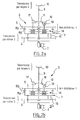
- Such a device is of a simplified embodiment compared to that of the structure illustrated with reference to FIGS. 2a and 2b: in particular, it does not does not require the manufacture of parts having grooves training; entrainment of the exit piece by the entry piece is in fact ensured by the set of friction discs.
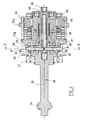
- the overriding device which is represented in FIGS. 3 to 5 comprises a part 20 for manual input control, a part 21 an output gear, part of which 21a constitutes a toothed wheel which cooperates with complementary means of a transmission chain allowing said wheel 21a to actuate the distributor of a circuit hydraulic of a flight control, a piece 22 of input gear a part 22a of which constitutes a toothed wheel which cooperates with additional means of a transmission chain allowing a electric motor to drive said input part 22.
- the manual control part 20 has a shaft 23 which carries a pinion 24 intended to mesh with connected reduction means mechanically to a pilot control lever.
- This part 20 is mounted in a bearing 27 fixed on the frame - referenced by 28 - of the overriding device.
- This level 27 authorizes the pivoting of said part 20 about the axis, referenced by A, of its shaft 23.
- Parts 21 and 22 are co-axial with part 20 and are mounted in the frame 28 while being able to rotate about their axis.
- the shaft 23 further carries a plate 25 which extends transversely to the axis of said shaft 23 and which defines a ramp cam 26.
- An intermediate piece 29 roller carrier is interposed between this plate 25 and the output part 21.
- This part 29 has a general disc shape and is of same axis as parts 20 and 21.
- rollers 30 which are diametrically opposite one by relative to the other on the part 29 and which are mounted in rotation around axes 31 which extend radially with respect to the axis of the shaft 23.
- rollers 30 roll on the cam ramp 26 of the plate 25, the parts 20 and 21 being shaped so as to allow the part 29 to move along its axis, from one position to another between the parts 20 and 21, when said part 29 rotates relative to part 20 and the rollers 30 roll on the cam ramp 26.
- the ramp 26 may have a succession of several slopes. Alternatively, it may also have a slope evolving without discontinuity allowing a movement of progressive, smooth manual control of the torque required exercise the pilot.
- the axes 31 of the rollers 30 further constitute keys which their end in the vicinity of the axis of the parts 20 and 29 are engaged in a cylindrical part 32 forming a pusher which extends in a complementary sheath 33 which extends the plate 25 axially from the side of said plate opposite the shaft 23.
- the keys formed by these axes 31 thus allow the intermediate part 29 to entrain in its axial displacement of the cylindrical part 32.
- the displacement of the pusher that constitutes this cylindrical part 32 allows, when said pusher leaves its sheath, operate switches (not shown) which are arranged to the right of said pusher and which control inside of the cockpit of the aircraft triggering visual or audible signals intended to indicate that the manual control has taken control over electrical control.
- the axes 31 constitute keys which come in stop, at their end opposite the axis also, at their end opposite the axis of parts 20 and 29, on bearing surfaces 34 that the output part 29 presents.
- the part intermediate 29 rotates with respect to the output part 21 until it comes into abutment on the bearing surfaces of the output piece 21.
- the rollers 30 roll on the cam ramp 26 to a stop position, then the part 20 drives the output part 21 via the keys formed by the axes 31.
- a coil spring 38 is mounted between the workpiece intermediate roller holder 29 and the output piece 21. This coil spring 38 allows the intermediate roller-bearing part 29 to be pushed back into its position where it is distant from part 21, when the pilot relaxes his effort on part 20
- a set of friction discs 35 is interposed between the outlet piece 21 and inlet piece 22.
- This set of friction discs 35 consists of five discs of 35a carbon friction interposed between six metallic friction discs 35b, which are repelled on each other by means of springs 36 which are housed in recesses provided for this purpose in the entrance room 22.
- These springs 36 which are for example helical springs, exert against these friction discs a force which is parallel to the axis of the parts of the device, so that the friction discs are normally in engagement with each other, the input wheel 22 driving in rotation the output wheel 21.
- the intermediate part 29 roller carrier further comprises a pusher element 37 which extends parallel to the axis A in a recess provided for this purpose through the first nine friction discs 25 which are superimposed from part 21.
- This pusher element 37 is of a length such that it comes to bear on the last two friction discs of disc set 35, when the intermediate piece 29 has moved along the axis A to the position where it is closest to the part 21, due to the rolling of the rollers 30 on the cam ramp 26.
- the input part 22 drives the outlet 21 via friction discs 35 which are then all held in place by the springs 36.
- the distributor of the hydraulic circuit is controlled by the electric motor, which is itself controlled by a computer of the aircraft.
- the pilot decides to take control of the electric motor and the computer, it exerts on the part 20, a force which firstly drives the rollers-29 door part in rotation by relative to the part 21 until the keys 31 abut on the complementary bearing surfaces of said part 21.
- the part carries rollers 29 is then blocked by said part 21, so that part 20 rotates relative to said intermediate piece 29 and that the rollers 30 roll on the ramp 26 of the plate 25.
- the pusher 37 is then advanced in its housing through the friction discs 35 and bears on the last two friction discs, on which it exerts an opposing force to that of springs 36.
- the force exerted on the other discs of friction is then released so that the part 22 no longer drives the part 21, while a friction force is transmitted between the part 22 and the part 20 via the last two friction discs and pusher 37.
- the pusher 32 is in turn out, so that the switches which control signals inside the passenger compartment are toggled.
- Pusher 37 disengages with respect to the last two friction discs and the springs 36 again exert their force on all of the friction discs 35.
- the part 22 again drives the part 21 by means of friction discs 35.
- the structure of the overriding device which comes to be described allows the pilot to exercise his command with a couple relatively low actuation (of the order of 0.2 mN for example).
- the overriding device has been described here in the case of a one of its applications is aircraft flight control favorite. It could, however, find application more generally. in all cases where it may be necessary to provide for an override manual in a transmission chain normally driven by a electric motor.
Landscapes
- Engineering & Computer Science (AREA)
- Mechanical Engineering (AREA)
- Automation & Control Theory (AREA)
- Aviation & Aerospace Engineering (AREA)
- General Engineering & Computer Science (AREA)
- Mechanical Operated Clutches (AREA)
- Transmission Devices (AREA)
Abstract
Description
- une roue d'engrenage de sortie 5, qui engrène avec des moyens complémentaires du distributeur 1 de commande hydraulique,
- une roue d'engrenage d'entrée 6, qui est coaxiale à la roue d'engrenage 5 et qui engrène avec des moyens complémentaires d'une chaíne de transmission entraínée par le moteur électrique 2,
- un ensemble intermédiaire 7 qui est interposé entre les deux roues d'engrenage 5 et 6 en étant coaxial à celles-ci ; cet ensemble 7 est entraíné en rotation par la roue d'entrée 6 ; il comporte un jeu de cannelures 8a qui coopère avec de cannelures complémentaires 8b de la roue d'engrenage de sortie 5 pour, en fonctionnement normal, permettre à la roue d'entrée 6 d'entraíner la roue de sortie 5 via ledit ensemble intermédiaire 7,
- un arbre 9 qui est coaxial aux roues 5 et 6 et à l'ensemble intermédiaire 7 ; cet arbre 9 comporte d'une part un pignon 10 qui coopère avec des moyens complémentaires d'une chaíne de transmission, qui permet aux moyens d'actionnement 4 d'entraíner ledit arbre 9 ; il comporte d'autre part un plateau 11 qui présente une came 12 sur laquelle des moyens de roulement 13 que présentent l'ensemble intermédiaire 7 sont en appui ; il comporte en outre des moyens formant butée, schématisés par une fourche 17 sur les figures 2a et 2b, qui permettent à l'arbre 9 d'entraíner en rotation la roue 6, lorsque le pilote agit sur l'arbre 9.
- la pièce intermédiaire comporte des moyens formant butée qui, à l'issue d'un déplacement de la pièce intermédiaire sur la came sous l'effet d'un couple exercé sur la pièce de commande manuelle, viennent en appui sur au moins une surface complémentaire de la pièce de sortie, la pièce de commande manuelle entraínant alors la pièce intermédiaire et la pièce de sortie;
- une partie des disques de friction présente une zone d'appui sur laquelle l'élément formant poussoir vient en appui à l'issue d'un déplacement de la pièce intermédiaire sur la came ; de cette façon, la pièce d'entrée propose toujours au couple exercé par le pilote sur la pièce de commande manuelle un effort de signe contraire qui lui est transmis par l'intermédiaire des disques de friction qui restent en prise, de l'élément formant poussoir et de la pièce intermédiaire ; cette friction est importante dans la mesure où elle assure pour le pilote un point d'appui par rapport auquel il peut ajuster son effort.
- les autres disques de friction sont traversés par un évidement autorisant le déplacement de l'élément formant poussoir ;
- le jeu de disques de friction comporte une pluralité de disques de carbone alternant avec des disques métalliques ;
- le jeu de disques de friction comporte au moins cinq disques de carbone ;
- l'élément formant poussoir vient en appui sur deux disques du jeu de disques de friction;
- la pièce intermédiaire porte deux galets qui roulent sur la came.
- les axes des galets constituent des clavettes aptes à venir en appui sur des surfaces complémentaires de la pièce de sortie ;
- les axes des galets constituent des clavettes qui sont engagées dans une pièce cylindrique montée coulissante dans un fourreau qui prolonge co-axialement la pièce de commande manuelle, ladite pièce cylindrique étant entraínée en coulissement par rapport audit fourreau lorsque la pièce intermédiaire se déplace sur la came et constituant un poussoir apte à commander le basculement d'au moins un interrupteur ;
- le dispositif comporte un ressort hélicoïdal qui est interposé co-axialement entre la pièce intermédiaire et la pièce de sortie et qui assure un déplacement de retour de la pièce intermédiaire sur la came, lorsque l'effort sur la pièce de commande manuelle est relâché.
- la figure 1, déjà discutée, est un schéma synoptique illustrant la disposition d'un dispositif de surpassement dans une chaíne de commande ;
- les figures 2a et 2b sont des schémas synoptiques illustrant une structure de dispositif de surpassement qui pose un certain nombre de problèmes que l'invention se propose de résoudre ;
- la figure 3 est une représentation schématique en perspective d'un ensemble de surpassement conforme à un mode de réalisation possible pour l'invention ;
- la figure 4 est une représentation schématique en coupe de l'ensemble de surpassement de la figure 3 ;
- la figure 5 est une vue en coupe selon la ligne V-V de la figure 4.
Claims (12)
- Dispositif de surpassement comportant une pièce de commande manuelle (20), une pièce d'engrenage d'entrée (22) et une pièce d'engrenage de sortie (21) qui sont montées co-axialement en rotation, des moyens (35) étant interposés entre la pièce d'engrenage d'entrée (22) et la pièce d'engrenage de sortie (21), pour, en fonctionnement normal, permettre à la pièce d'engrenage d'entrée (22) d'entraíner en rotation la pièce d'engrenage de sortie (21), la pièce de commande manuelle (20) portant en outre une came (26) qui, en coopération avec des moyens complémentaires (37) qui comportent une pièce intermédiaire (29) apte à rouler sur ladite came (26), permet de désengager les moyens (35) interposés entre la pièce d'engrenage d'entrée (22) et la pièce d'engrenage de sortie (21) sous l'effet d'un couple exercé sur la pièce de commande manuelle (20), le dispositif comportant également des moyens (31) permettant alors à la pièce de commande manuelle (20) d'entraíner la pièce d'engrenage de sortie, caractérisé en ce que les moyens d'entraínement qui sont interposés entre la pièce d'engrenage d'entrée (22) et la pièce d'engrenage de sortie (21) comportent un jeu de disques de friction (35) et des moyens ressorts (36) aptes à exercer un effort comprimant lesdits disques (35) les uns sur les autres et en ce que la pièce intermédiaire (29) apte à rouler sur la came (26) porte au moins un élément formant poussoir (37) qui, à l'issue d'un déplacement de la pièce intermédiaire (29) sur la came (26) sous l'effet d'un couple exercé sur la pièce de commande manuelle (20), vient exercer un effort qui s'oppose à celui des moyens ressorts (36) et qui relâche l'effort de friction sur au moins une partie des disques (35).
- Dispositif selon la revendication 1, caractérisé en ce que la pièce intermédiaire comporte des moyens (31) formant butée qui, à l'issue d'un déplacement de la pièce intermédiaire (29) sur la came sous l'effet d'un couple exercé sur la pièce de commande manuelle (20), viennent en appui sur au moins une surface complémentaire de la pièce de sortie (21), la pièce de commande manuelle (20) entraínant alors la pièce intermédiaire (29) et la pièce de sortie (21).
- Dispositif selon la revendication 2, caractérisé en ce qu'une partie des disques de friction (35) présente une zone d'appui sur laquelle l'élément formant poussoir (37) vient en appui à l'issue d'un déplacement de la pièce intermédiaire (29) sur la came (26).
- Dispositif selon la revendication 3, caractérisé en ce que les autres disques de friction sont traversés par un évidement autorisant le déplacement de l'élément formant poussoir (37).
- Dispositif selon l'une des revendications précédentes, caractérisé en ce que le jeu de disques de friction (35) comporte une pluralité de disques de carbone (35a) alternant avec des disques métalliques (35b).
- Dispositif selon la revendication 5, caractérisé en ce que le jeu de disques de friction (35) comporte au moins cinq disques de carbone (35a).
- Dispositif selon les revendications 3 et 6 prises en combinaison, caractérisé en ce que l'élément formant poussoir (37) vient en appui sur deux disques du jeu de disques de friction (35).
- Dispositif selon l'une des revendications précédentes, caractérisé en ce que la pièce intermédiaire porte deux galets (30) qui roulent sur la came (26).
- Dispositif selon les revendications 2 et 8 prises en combinaison, caractérisé en ce que les axes des galets (30) constituent des clavettes (31) aptes à venir en appui sur des surfaces complémentaires de la pièce de sortie (21).
- Dispositif selon l'une des revendications 8 ou 9, caractérisé en ce que les axes des galets (30) constituent des clavettes (31) qui sont engagées dans une pièce cylindrique (32) montée coulissante dans un fourreau (33) qui prolonge co-axialement la pièce de commande manuelle (20), ladite pièce cylindrique (32) étant entraínée en coulissement par rapport audit fourreau (33) lorsque la pièce intermédiaire (29) se déplace sur la came (26) et constituant un poussoir apte à commander le basculement d'au moins un interrupteur.
- Dispositif selon l'une des revendications précédentes, caractérisé en ce qu'il comporte un ressort hélicoïdal qui est interposé coaxialement entre la pièce intermédiaire et la pièce de sortie et qui assure un déplacement de retour de la pièce intermédiaire sur la came, lorsque l'effort sur la pièce de commande manuelle est relâché.
- Dispositif de surpassement pour commande de vol, caractérisé en ce qu'il est constitué par un dispositif selon l'une des revendications précédentes.
Applications Claiming Priority (2)
| Application Number | Priority Date | Filing Date | Title |
|---|---|---|---|
| FR9915308A FR2801864B1 (fr) | 1999-12-02 | 1999-12-02 | Dispositif de surpassement manuel, notamment pour commande de vol d'un aeronef |
| FR9915308 | 1999-12-02 |
Publications (2)
| Publication Number | Publication Date |
|---|---|
| EP1104740A1 true EP1104740A1 (fr) | 2001-06-06 |
| EP1104740B1 EP1104740B1 (fr) | 2006-02-08 |
Family
ID=9552900
Family Applications (1)
| Application Number | Title | Priority Date | Filing Date |
|---|---|---|---|
| EP00403352A Expired - Lifetime EP1104740B1 (fr) | 1999-12-02 | 2000-11-30 | Dispositif de surpassement manuel, notamment pour commande de vol d'un aéronef |
Country Status (5)
| Country | Link |
|---|---|
| US (1) | US6491148B2 (fr) |
| EP (1) | EP1104740B1 (fr) |
| DE (1) | DE60025900T2 (fr) |
| ES (1) | ES2254119T3 (fr) |
| FR (1) | FR2801864B1 (fr) |
Cited By (2)
| Publication number | Priority date | Publication date | Assignee | Title |
|---|---|---|---|---|
| FR2970697A1 (fr) * | 2011-01-24 | 2012-07-27 | Sagem Defense Securite | Dispositif d'actionnement d'un equipement pilotable automatiquement ou manuellement avec detection de la reprise du pilotage manuel |
| CN110077632A (zh) * | 2019-05-14 | 2019-08-02 | 中国空间技术研究院 | 一种手自动一体化起旋装置及微重力翻滚状态模拟系统 |
Families Citing this family (2)
| Publication number | Priority date | Publication date | Assignee | Title |
|---|---|---|---|---|
| US6692399B2 (en) * | 2001-12-19 | 2004-02-17 | Moog Inc. | Differential torque limiter |
| EP2947005B1 (fr) * | 2014-05-20 | 2018-07-04 | Mecaer Aviation Group S.p.A. | Système de commande de vol hybride d'aéronef |
Citations (3)
| Publication number | Priority date | Publication date | Assignee | Title |
|---|---|---|---|---|
| US2570585A (en) * | 1944-06-26 | 1951-10-09 | Bendix Aviat Corp | Disconnect device |
| US3091316A (en) * | 1960-09-16 | 1963-05-28 | Sperry Rand Corp | Overridable clutch mechanism |
| US5769362A (en) * | 1996-05-01 | 1998-06-23 | Safe Flight Instrument Corporation | Aircraft control mechanism for a speed brake |
Family Cites Families (7)
| Publication number | Priority date | Publication date | Assignee | Title |
|---|---|---|---|---|
| US3099338A (en) * | 1961-06-16 | 1963-07-30 | Byrne Doors Inc | Door operator |
| US4022309A (en) * | 1975-03-26 | 1977-05-10 | Philadelphia Gear Corporation | De-clutch mechanism for valve operator |
| US4429591A (en) * | 1979-03-13 | 1984-02-07 | Eim Company, Inc. | Drive shifting apparatus for valve control and the like |
| US4393965A (en) * | 1980-11-13 | 1983-07-19 | Andco Actuator Products, Inc. | Rotary actuator |
| US4474078A (en) * | 1982-06-21 | 1984-10-02 | Philadelphia Gear Corporation | Valve operator de-clutch mechanism |
| FR2729726B1 (fr) * | 1995-01-23 | 1997-04-18 | Antonov Automotive Europ | Embrayage multi-disques, transmission automatique ainsi equipee et procede de realisation |
| DE19819421C2 (de) * | 1998-04-30 | 2001-11-08 | Kiekert Ag | Schiebetürantrieb für die Schiebetür eines Kraftfahrzeuges |
-
1999
- 1999-12-02 FR FR9915308A patent/FR2801864B1/fr not_active Expired - Fee Related
-
2000
- 2000-11-30 EP EP00403352A patent/EP1104740B1/fr not_active Expired - Lifetime
- 2000-11-30 ES ES00403352T patent/ES2254119T3/es not_active Expired - Lifetime
- 2000-11-30 DE DE60025900T patent/DE60025900T2/de not_active Expired - Lifetime
- 2000-12-01 US US09/728,355 patent/US6491148B2/en not_active Expired - Lifetime
Patent Citations (3)
| Publication number | Priority date | Publication date | Assignee | Title |
|---|---|---|---|---|
| US2570585A (en) * | 1944-06-26 | 1951-10-09 | Bendix Aviat Corp | Disconnect device |
| US3091316A (en) * | 1960-09-16 | 1963-05-28 | Sperry Rand Corp | Overridable clutch mechanism |
| US5769362A (en) * | 1996-05-01 | 1998-06-23 | Safe Flight Instrument Corporation | Aircraft control mechanism for a speed brake |
Cited By (6)
| Publication number | Priority date | Publication date | Assignee | Title |
|---|---|---|---|---|
| FR2970697A1 (fr) * | 2011-01-24 | 2012-07-27 | Sagem Defense Securite | Dispositif d'actionnement d'un equipement pilotable automatiquement ou manuellement avec detection de la reprise du pilotage manuel |
| WO2012101122A1 (fr) * | 2011-01-24 | 2012-08-02 | Sagem Defense Securite | Dispositif d'actionnement d'un equipement pilotable automatiquement ou manuellement avec detection de la reprise du pilotage manuel |
| US8907536B2 (en) | 2011-01-24 | 2014-12-09 | Sagem Defense Securite | Device for actuating an item of equipment that can be controlled automatically or manually, with detection of take-up of manual control |
| RU2538831C1 (ru) * | 2011-01-24 | 2015-01-10 | Сажем Дефанс Секюрите | Приводное устройство узла, управляемое автоматически или вручную, с обнаружением перехода на ручное управление |
| CN110077632A (zh) * | 2019-05-14 | 2019-08-02 | 中国空间技术研究院 | 一种手自动一体化起旋装置及微重力翻滚状态模拟系统 |
| CN110077632B (zh) * | 2019-05-14 | 2023-08-01 | 中国空间技术研究院 | 一种手自动一体化起旋装置及微重力翻滚状态模拟系统 |
Also Published As
| Publication number | Publication date |
|---|---|
| US6491148B2 (en) | 2002-12-10 |
| DE60025900T2 (de) | 2006-08-03 |
| ES2254119T3 (es) | 2006-06-16 |
| DE60025900D1 (de) | 2006-04-20 |
| FR2801864B1 (fr) | 2002-02-22 |
| EP1104740B1 (fr) | 2006-02-08 |
| FR2801864A1 (fr) | 2001-06-08 |
| US20010002687A1 (en) | 2001-06-07 |
Similar Documents
| Publication | Publication Date | Title |
|---|---|---|
| FR3060630B1 (fr) | Commande d'ouverture affleurante a ejection et retraction mecanique ou electrique. | |
| FR2743107A1 (fr) | Volet a actionnement electrique pour l'equipement d'immeubles | |
| EP3581742A1 (fr) | Commande motorisée de poignée de porte affleurante et son procédé de fonctionnement | |
| EP2275719A1 (fr) | Boîte de vitesses comportant un moyen de blocage d'un arbre de sortie et véhicule comportant une telle boîte de vitesses | |
| EP0957293B1 (fr) | Actionneur électro-mécanique du type à système vis/écrou | |
| CA2825056C (fr) | Dispositif d'actionnement d'un equipement pilotable automatiquement ou manuellement avec detection de la reprise du pilotage manuel | |
| EP0990098B1 (fr) | Actionneur electromecanique pour boite de vitesses mecanique | |
| FR2803890A1 (fr) | Barillet de commande pour boite de vitesses et boite de vitesses equipees d'un tel barillet | |
| EP1104740B1 (fr) | Dispositif de surpassement manuel, notamment pour commande de vol d'un aéronef | |
| FR2878487A1 (fr) | Mecanisme de verrouillage d'un arbre de transmission d'un vehicule automobile | |
| EP1108169B1 (fr) | Actionneur electromecanique pour boite de vitesse de vehicule automobile | |
| FR2774447A1 (fr) | Vehicule equipe d'un dispositif de manoeuvre automatisee d'une boite a vitesses | |
| EP2189995B1 (fr) | Commande d'appareillage électrique haute ou moyenne tension à mécanisme à double accrochage amélioré et procédé d'armement associé. | |
| WO2004059110A1 (fr) | Procede de commande d'une serrure electrique munie d'un embrayage | |
| FR2892082A1 (fr) | Transmission, notamment entre un arbre moteur et un arbre d'entrainement de roues d'un engin, engin de preference automoteur equipe d'une telle transmission et son procede de commande en fonctionnement | |
| FR2880852A1 (fr) | Boite a gants de vehicule automobile | |
| EP1026345B1 (fr) | Serrure pour ouvrant de véhicule comportant un système électrique d'assistance a l'ouverture | |
| FR2476378A1 (fr) | Mecanisme de commutation pour dispositif electrique de commande d'un mouvement lineaire ou rotatif | |
| EP0885362A1 (fr) | Limiteur de force debrayable pour verin electrique lineaire a vis | |
| EP0630495B1 (fr) | Dispositif d'actionnement d'un systeme tel qu'un embrayage ou une boite de vitesse | |
| FR2756320A1 (fr) | Dispositif de detection de fin de course et mecanisme d'entrainement de volet roulant incorporant un tel dispositif | |
| EP1549818B1 (fr) | Dispositif de commande de store motorise | |
| EP1865140B1 (fr) | Dispositif d'entraînement en ouverture ou en fermeture d'un ouvrant coulissant, et ouvrant coulissant équipé d'un tel dispositif d'entraînement | |
| FR2811051A1 (fr) | Dispositif de commande pour relier un pignon monte fou sur un arbre et cet arbre, notamment pour boite de vitesses de vehicule automobile | |
| FR2637668A1 (fr) | Dispositif lineaire reducteur/multiplicateur bi-directionnel de course et d'effort |
Legal Events
| Date | Code | Title | Description |
|---|---|---|---|
| PUAI | Public reference made under article 153(3) epc to a published international application that has entered the european phase |
Free format text: ORIGINAL CODE: 0009012 |
|
| AK | Designated contracting states |
Kind code of ref document: A1 Designated state(s): DE ES FR GB IT |
|
| AX | Request for extension of the european patent |
Free format text: AL;LT;LV;MK;RO;SI |
|
| 17P | Request for examination filed |
Effective date: 20011119 |
|
| AKX | Designation fees paid |
Free format text: DE ES FR GB IT |
|
| GRAP | Despatch of communication of intention to grant a patent |
Free format text: ORIGINAL CODE: EPIDOSNIGR1 |
|
| RAP1 | Party data changed (applicant data changed or rights of an application transferred) |
Owner name: TRW SYSTEMES AERONAUTIQUES CIVILS |
|
| RAP1 | Party data changed (applicant data changed or rights of an application transferred) |
Owner name: GOODRICH ACTUATION SYSTEMS SAS |
|
| GRAS | Grant fee paid |
Free format text: ORIGINAL CODE: EPIDOSNIGR3 |
|
| GRAA | (expected) grant |
Free format text: ORIGINAL CODE: 0009210 |
|
| AK | Designated contracting states |
Kind code of ref document: B1 Designated state(s): DE ES FR GB IT |
|
| PG25 | Lapsed in a contracting state [announced via postgrant information from national office to epo] |
Ref country code: IT Free format text: LAPSE BECAUSE OF FAILURE TO SUBMIT A TRANSLATION OF THE DESCRIPTION OR TO PAY THE FEE WITHIN THE PRE;WARNING: LAPSES OF ITALIAN PATENTS WITH EFFECTIVE DATE BEFORE 2007 MAY HAVE OCCURRED AT ANY TIME BEFORE 2007. THE CORRECT EFFECTIVE DATE MAY BE DIFFERENT FROM THE ONE RECORDED.SCRIBED TIME-LIMIT Effective date: 20060208 |
|
| REG | Reference to a national code |
Ref country code: GB Ref legal event code: FG4D Free format text: NOT ENGLISH |
|
| REF | Corresponds to: |
Ref document number: 60025900 Country of ref document: DE Date of ref document: 20060420 Kind code of ref document: P |
|
| GBT | Gb: translation of ep patent filed (gb section 77(6)(a)/1977) |
Effective date: 20060524 |
|
| REG | Reference to a national code |
Ref country code: ES Ref legal event code: FG2A Ref document number: 2254119 Country of ref document: ES Kind code of ref document: T3 |
|
| PLBE | No opposition filed within time limit |
Free format text: ORIGINAL CODE: 0009261 |
|
| STAA | Information on the status of an ep patent application or granted ep patent |
Free format text: STATUS: NO OPPOSITION FILED WITHIN TIME LIMIT |
|
| 26N | No opposition filed |
Effective date: 20061109 |
|
| PGFP | Annual fee paid to national office [announced via postgrant information from national office to epo] |
Ref country code: ES Payment date: 20121123 Year of fee payment: 13 |
|
| REG | Reference to a national code |
Ref country code: ES Ref legal event code: FD2A Effective date: 20150331 |
|
| PG25 | Lapsed in a contracting state [announced via postgrant information from national office to epo] |
Ref country code: ES Free format text: LAPSE BECAUSE OF NON-PAYMENT OF DUE FEES Effective date: 20131201 |
|
| REG | Reference to a national code |
Ref country code: FR Ref legal event code: PLFP Year of fee payment: 16 |
|
| PGFP | Annual fee paid to national office [announced via postgrant information from national office to epo] |
Ref country code: GB Payment date: 20151027 Year of fee payment: 16 Ref country code: DE Payment date: 20151022 Year of fee payment: 16 Ref country code: IT Payment date: 20151023 Year of fee payment: 16 |
|
| PGFP | Annual fee paid to national office [announced via postgrant information from national office to epo] |
Ref country code: FR Payment date: 20151023 Year of fee payment: 16 |
|
| REG | Reference to a national code |
Ref country code: DE Ref legal event code: R119 Ref document number: 60025900 Country of ref document: DE |
|
| GBPC | Gb: european patent ceased through non-payment of renewal fee |
Effective date: 20161130 |
|
| REG | Reference to a national code |
Ref country code: FR Ref legal event code: ST Effective date: 20170731 |
|
| PG25 | Lapsed in a contracting state [announced via postgrant information from national office to epo] |
Ref country code: FR Free format text: LAPSE BECAUSE OF NON-PAYMENT OF DUE FEES Effective date: 20161130 Ref country code: IT Free format text: LAPSE BECAUSE OF NON-PAYMENT OF DUE FEES Effective date: 20161130 |
|
| PG25 | Lapsed in a contracting state [announced via postgrant information from national office to epo] |
Ref country code: GB Free format text: LAPSE BECAUSE OF NON-PAYMENT OF DUE FEES Effective date: 20161130 Ref country code: DE Free format text: LAPSE BECAUSE OF NON-PAYMENT OF DUE FEES Effective date: 20170601 |