EP1104734A1 - Method and apparatus for detecting railroad car derailment - Google Patents
Method and apparatus for detecting railroad car derailment Download PDFInfo
- Publication number
- EP1104734A1 EP1104734A1 EP98936719A EP98936719A EP1104734A1 EP 1104734 A1 EP1104734 A1 EP 1104734A1 EP 98936719 A EP98936719 A EP 98936719A EP 98936719 A EP98936719 A EP 98936719A EP 1104734 A1 EP1104734 A1 EP 1104734A1
- Authority
- EP
- European Patent Office
- Prior art keywords
- rolling stock
- vertical acceleration
- derailment
- carbody
- acceleration
- Prior art date
- Legal status (The legal status is an assumption and is not a legal conclusion. Google has not performed a legal analysis and makes no representation as to the accuracy of the status listed.)
- Granted
Links
Images


Classifications
-
- B—PERFORMING OPERATIONS; TRANSPORTING
- B60—VEHICLES IN GENERAL
- B60T—VEHICLE BRAKE CONTROL SYSTEMS OR PARTS THEREOF; BRAKE CONTROL SYSTEMS OR PARTS THEREOF, IN GENERAL; ARRANGEMENT OF BRAKING ELEMENTS ON VEHICLES IN GENERAL; PORTABLE DEVICES FOR PREVENTING UNWANTED MOVEMENT OF VEHICLES; VEHICLE MODIFICATIONS TO FACILITATE COOLING OF BRAKES
- B60T17/00—Component parts, details, or accessories of power brake systems not covered by groups B60T8/00, B60T13/00 or B60T15/00, or presenting other characteristic features
- B60T17/18—Safety devices; Monitoring
- B60T17/22—Devices for monitoring or checking brake systems; Signal devices
- B60T17/228—Devices for monitoring or checking brake systems; Signal devices for railway vehicles
-
- B—PERFORMING OPERATIONS; TRANSPORTING
- B60—VEHICLES IN GENERAL
- B60T—VEHICLE BRAKE CONTROL SYSTEMS OR PARTS THEREOF; BRAKE CONTROL SYSTEMS OR PARTS THEREOF, IN GENERAL; ARRANGEMENT OF BRAKING ELEMENTS ON VEHICLES IN GENERAL; PORTABLE DEVICES FOR PREVENTING UNWANTED MOVEMENT OF VEHICLES; VEHICLE MODIFICATIONS TO FACILITATE COOLING OF BRAKES
- B60T7/00—Brake-action initiating means
- B60T7/12—Brake-action initiating means for automatic initiation; for initiation not subject to will of driver or passenger
- B60T7/124—Brakes for railway vehicles coming into operation in case of accident, derailment or damage of rolling stock or superstructure
-
- B—PERFORMING OPERATIONS; TRANSPORTING
- B61—RAILWAYS
- B61F—RAIL VEHICLE SUSPENSIONS, e.g. UNDERFRAMES, BOGIES OR ARRANGEMENTS OF WHEEL AXLES; RAIL VEHICLES FOR USE ON TRACKS OF DIFFERENT WIDTH; PREVENTING DERAILING OF RAIL VEHICLES; WHEEL GUARDS, OBSTRUCTION REMOVERS OR THE LIKE FOR RAIL VEHICLES
- B61F9/00—Rail vehicles characterised by means for preventing derailing, e.g. by use of guide wheels
- B61F9/005—Rail vehicles characterised by means for preventing derailing, e.g. by use of guide wheels by use of non-mechanical means, e.g. acoustic or electromagnetic devices
Definitions
- the present invention relates to a derailment detecting method and derailment detecting apparatus for automatically detecting derailment of rolling stock.
- the derailment In general, in the event of derailment of rolling stock, the derailment must be detected by the motorman etc. of the rolling stock, by visual recognition or personal sensation of the motorman etc. However, in the case that the derailment should occur at a car coupled in the rear, even during manned operation, there would be possibilities that the motorman etc. could fail to recognize the derailment. For automatic unmanned operation of rolling stock, it is necessary to prevent the derailed rolling stock from keeping running and stop the rolling stock immediately upon occurrence of the derailment.
- An object of the present invention is, therefore, to provide a derailment detecting method and derailment detecting apparatus for rolling stock capable of automatically detecting the derailment of rolling stock.
- a derailment detecting method for rolling stock according to the present invention is applied to the rolling stock comprises a truck having wheels rolling on rails and spring rigging, and a carbody to which the truck is attached.
- the rolling stock is preliminarily made to travel at varying running velocities on a predetermined route.
- a maximum of vertical acceleration at the carbody above the spring rigging is measured in a predetermined frequency range and at each of the varying running velocities. Then, from each maximum, a limit vertical acceleration is defined as a threshold for detecting the derailment at each running velocity.
- real running velocity of the rolling stock is detected and real vertical acceleration is also detected at the carbody above the spring rigging.
- a component in the above-stated frequency range is extracted from the real vertical acceleration detected. In the case that an absolute value of the real vertical acceleration in the mentioned frequency range exceeds the limit vertical acceleration corresponding to the real running velocity detected, it is then determined that the rolling stock is derailed.
- the derailment can be detected accurately and surely by defining the limit vertical acceleration in correspondence to the real running velocity of the rolling stock and comparing the vertical acceleration at the carbody etc. with the limit vertical acceleration corresponding to the real running velocity during the actual traveling of the rolling stock as described above.
- the limit vertical acceleration it is preferable to set the limit vertical acceleration to a value larger than the maximum of the vertical acceleration preliminarily measured.
- the aforementioned frequency range be a frequency range in which an absolute value of permissible vertical acceleration for assuring riding comfort is set at a minimum. Since in this frequency range the difference becomes definite between vertical acceleration during normal traveling and vertical acceleration at derailment, the derailment can be detected accurately and surely.
- the vertical acceleration is detected at the carbody above the spring rigging during running of the rolling stock on the rails. Then a vertical displacement amount is calculated by double integral of the vertical acceleration every predetermined evaluating time. This yields an amount of vertical displacement per evaluating time of the part above the spring rigging. In the event of the derailment of the rolling stock, the part above the spring rigging would descend over a predetermined amount.
- the rolling stock is derailed, in the case that the vertical displacement amount is negative and an absolute value thereof is not less than a predetermined reference value.
- Employed as the evaluating time is a time period between a start of descent of the carbody and arrival at half the height of the rails, in a free fall of one axle of the wheels by a distance equal to the height of the rails.
- the reference value for the comparison with the vertical displacement amount resulting from the double integral of the vertical acceleration be set to a value larger than a maximum change amount in the vertical direction of the spring rigging.
- the height of rails is greater than the maximum change amount in the vertical direction of the spring rigging during the normal traveling of rolling stock. Therefore, at the event of the derailment of rolling stock, the carbody etc. would descend by an amount exceeding the maximum change amount in the vertical direction of the spring rigging during the normal traveling and thus the derailment can be detected accurately and surely by setting the reference value for the comparison with the vertical displacement amount as described above.
- a derailment detecting apparatus for rolling stock according to the present invention is applied to the rolling stock comprises a truck having wheels rolling on rails and spring rigging, and a carbody to which the truck is attached.
- This derailment detecting apparatus comprises limit acceleration storing means, car velocity detecting means, acceleration storing means, filter means, and determining means.
- the limit acceleration storing means stores limit vertical acceleration as a threshold for detecting derailment.
- the limit vertical acceleration is defined for each running velocity, from a maximum of vertical acceleration in a predetermined frequency range, which is detected at each of varying running velocities during traveling of the rolling stock at the varying running velocities on a predetermined route and which appears at the carbody above the spring rigging.
- the car velocity detecting means detects the real running velocity of the rolling stock traveling on the route.
- the acceleration detecting means detects the real vertical acceleration at the carbody above the spring rigging during traveling of the rolling stock on the route.
- the filter means extracts a component in the above frequency range from the real vertical acceleration. Then the determining means determines that the rolling stock is derailed, in the case that an absolute value of the real vertical acceleration in the mentioned frequency range exceeds the limit vertical acceleration corresponding to the real running velocity.
- Another derailment detecting apparatus of rolling stock according to the present invention is applied to the rolling stock comprises a truck having wheels rolling on rails and spring rigging, and a carbody to which the truck is attached.
- This derailment detecting apparatus comprises acceleration detecting means, integrating means, and determining means.
- the acceleration detecting means detects the vertical acceleration at the carbody above the spring rigging during running of the rolling stock on the rails.
- the integrating means calculates a vertical displacement amount by double integral of the vertical acceleration every evaluating time, the evaluating time being a time period between a start of descent of the carbody and arrival at half the height of the rails, in a free fall of one axle of the wheels by a distance equal to the height of the rails.
- the determining means determines that the rolling stock is derailed, in the case that the vertical displacement amount is negative and an absolute value thereof is not less than a predetermined reference value.
- Fig. 1 is a schematic and structural diagram to show the rolling stock to which the derailment detecting apparatus according to the present invention is applied.
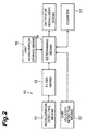
- Fig. 2 is a control block diagram of the derailment detecting apparatus for rolling stock according to the first embodiment of the present invention.
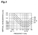
- Fig. 3 is a graph to show the relationship between frequency and absolute values of vertical acceleration at the carbody of rolling stock.
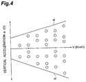
- Fig. 4 is a graph for illustrating a defining procedure of limit vertical acceleration.
- Fig. 5 is a control block diagram of the derailment detecting apparatus for rolling stock according to the second embodiment of the present invention.
- Fig. 6 is a graph for illustrating a setting procedure of evaluating time.
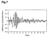
- Fig. 7 is a graph to exemplify temporal change of vertical acceleration upon occurrence of derailment detected by the acceleration detecting means of Fig. 5.
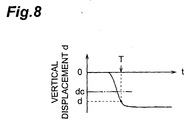
- Fig. 8 is a graph to show temporal change of vertical displacement calculated by the integration means of Fig. 5 from the vertical acceleration in Fig. 7.
- Fig. 9 is a control block diagram of the derailment detecting apparatus for rolling stock according to the third embodiment of the present invention.
- Fig. 1 is a schematic and structural diagram to show the rolling stock to which the derailment detecting apparatus for rolling stock according to the present invention is applied.
- the rolling stock 1 shown in Fig. 1 is driven by manned operation or by unmanned operation and comprises a carbody 2 and two trucks 3 attached to the carbody.
- Each truck 3 incorporates wheels 5 rolling on rails 4, and spring rigging 6 comprised of an air spring or the like.
- the spring rigging 6 expands and contracts in the vertical direction during traveling of the rolling stock 1 to relieve vibration appearing at the part above the spring rigging 6 (the part including the carbody 2).
- the derailment detecting apparatus 10 according to the first embodiment of the present invention is mounted on the carbody 2 for accommodating passengers so as to be located substantially right above each truck 3. In this way, two derailment detecting apparatus 10 are mounted on one rolling stock 1.
- Fig. 2 is a control block diagram of the derailment detecting apparatus 10.
- the derailment detecting apparatus 10 includes an acceleration detecting means 11 and a car velocity detecting means 12.
- the acceleration detecting means 11 is attached to the carbody 2 and detects a vertical component (a) of acceleration appearing at the carbody 2 above the spring rigging 6 of the truck 3 during traveling of the rolling stock 1 (the vertical component will be referred to hereinafter as "vertical acceleration (a)").
- the car velocity detecting means 12 detects the running velocity (v) during the traveling of the rolling stock 1.
- the car velocity detecting means 12 outputs a signal indicating the detected running velocity (v) of the rolling stock 1, to a determining means 14.
- the acceleration detecting means 11 is connected to a filter means 15 consisting of a band-pass filter or the like.
- This filter means 15 extracts a component in a predetermined frequency range (which is, for example, the frequency range of 6 to 20 Hz in this case, but which may also be set as the range of 4 to 8 Hz) from the output of the acceleration detecting means 11.
- a predetermined frequency range which is, for example, the frequency range of 6 to 20 Hz in this case, but which may also be set as the range of 4 to 8 Hz
- the rolling stock is designed and manufactured so that the relation between frequency f and absolute values of the vertical acceleration (a) at the carbody satisfies, for example, the characteristics illustrated in Fig. 3, in order to keep the riding comfort thereof good.
- Fig. 3 is a graph to show the relation between frequency f and absolute values of the vertical acceleration (a) at the carbody, in which characteristic lines are illustrated at respective grades G1, G1.5, G2, G3 of riding comfort.
- the acceleration below the characteristic line corresponding to each grade G1 to G3 is judged as being within a permissible range, whereas the acceleration above it as being off the permissible range.
- the absolute value of tolerance of vertical acceleration (permissible vertical acceleration) is set to be flat and smaller in this frequency range than in the other frequency ranges. That is, the difference becomes definite between the vertical acceleration during normal traveling and the vertical acceleration at derailment in the frequency range of 6 to 20 Hz, whereby the derailment can be detected accurately and surely.
- the signal indicating the vertical acceleration (a) in the frequency range of 6 to 20 Hz extracted by the filter means 15 is sent to the determining means 14.
- a limit acceleration storing means 16 is connected to the determining means 14 and the limit acceleration storing means 16 stores data indicating limit vertical acceleration (al) defined at each predetermined velocity as a threshold for detection of derailment.
- the determining means 14 determines whether the absolute value of the vertical acceleration (a) in the frequency range of 6 to 20 Hz is over the limit vertical acceleration (al) corresponding to the running velocity (v) detected by the car velocity detecting means 12, in accordance with the signal indicating the vertical acceleration (a), which is received through the filter means 15 from the acceleration detecting means 11, and the signal indicating the running velocity (v), which is received from the car velocity detecting means 12.
- the determining means 14 is connected to an operation unit of the rolling stock 1 or an automatic train stop device or the like, which is not illustrated.
- the determining means 14 outputs a derailment signal indicating the derailment of rolling stock 1, to the operation unit or the like when the absolute value of the vertical acceleration (a) becomes over the limit vertical acceleration (al).
- a derailment signal For example, power running of the rolling stock 1 is terminated and emergency brakes are actuated to stop the rolling stock 1 immediately. It is also possible to provide the operation unit with a derailment alarm lamp and to make the derailment alarm lamp blink when the derailment signal is outputted.
- a preferred configuration is such that a counter 17 is connected to the determining means 14, as shown in Fig 2, and the rolling stock 1 is judged as being derailed when there occur a predetermined number of such events that the absolute value of the vertical acceleration (a) exceeds the limit vertical acceleration (al) corresponding to the running velocity (v), within a predetermined time period.
- the rolling stock 1 is preliminarily made to travel at varying running velocities (v) on a predetermined route (use line).
- the vertical acceleration (a) appearing at the carbody 2 above the spring rigging 6 is measured in the frequency range of 6 to 20 Hz.
- the limit vertical acceleration (al) is determined from the vertical acceleration (a) in the frequency range of 6 to 20 Hz.
- the limit vertical acceleration (al) can be determined by plotting maximums of the vertical acceleration (a) corresponding to the respective running velocities (v), preliminarily measured, defining straight lines passing through values greater than the maximums, and setting values on each straight line as the limit vertical acceleration (al), as shown in Fig. 4. Then the limit vertical acceleration (al) thus obtained is stored in the limit acceleration storing means 16.
- the running velocity (v) real running velocity
- the vertical acceleration (a) real vertical acceleration
- the filter means 15 extracts the component in the frequency range of 6 to 20 Hz from the vertical acceleration (a) detected.
- the determining means 14 determines that the rolling stock 1 is derailed.
- the derailment can be detected accurately and surely by defining the limit vertical acceleration (al) corresponding to the running velocity (v) of the rolling stock 1 and comparing the vertical acceleration (a) appearing at the carbody 2 etc. with the limit vertical acceleration (al) corresponding to the running velocity (v) during the actual traveling of the rolling stock 1.
- the limit vertical acceleration (al) was set so as to vary corresponding to the running velocity, but the invention is not limited to this. Namely, the limit vertical acceleration (al) may also be set to be constant.
- the determining means 14 can be configured so as to output the derailment signal when the absolute value of the vertical acceleration (a) received from the filter means 15 becomes, for example, over 0.2 G.
- Fig. 5 is a control block diagram of the derailment detecting apparatus according to the second embodiment of the present invention.
- the derailment detecting apparatus 20 shown in Fig. 5 is also provided two units per rolling stock 1, as in the case of the aforementioned derailment detecting apparatus 10.
- the derailment detecting apparatus 20 incorporates an acceleration detecting means 21 for detecting the vertical acceleration (a) at the carbody 2 above the spring rigging 6 of the truck 3 during traveling of the rolling stock 1.
- the acceleration detecting means 21 is attached to the carbody 2, which is the part above the spring rigging 6.
- the acceleration detecting means 21 is connected to an integrating means 22 and the integrating means 22 executes the double integral of output from the acceleration detecting means 21 to calculate a vertical displacement amount (d) at the mount position of the acceleration detecting means 21.
- the integrating means 22 executes the double integral of the vertical acceleration (a) every evaluating time (T), the evaluating time (T) (see Fig. 6) being defined as a time period from a start of descent of the carbody 2 to arrival at half the height of the rails 4, i.e., at h/2 (see Fig. 1) in a free fall of one axle of wheels 5 by a distance equal to the height h of the rails 4, to obtain the vertical displacement amount (d).
- This evaluating time (T) is preliminarily calculated as a value inherent to the rolling stock 1 equipped with the derailment detecting apparatus 20, by computer simulations or the like.
- the integrating means 22 executes the double integral with the initial velocity of zero, for calculating the vertical displacement amount (d).
- the double integral by the integrating means 22 is carried out in a state in which all integration constants are zero.
- the arithmetic result calculated by the integrating means 22 is sent to the determining means 23.
- the determining means 23 determines that the rolling stock 1 is derailed, in the case that the vertical displacement amount (d) is negative and an absolute value thereof is not less than a predetermined reference value (dc) (which is, for example, 40 mm in this case). It is preferable here that the reference value (dc) for the comparison with the vertical displacement amount (d) obtained by the double integral of the vertical acceleration (a) be set to a value greater than a maximum change amount in the vertical direction of the spring rigging 6 during the normal traveling of the rolling stock 1. As a result, it is possible to surely discriminate the vertical displacement of the carbody 2 etc. in the event of derailment and the steady-state vertical displacement of the carbody 2 etc. during the normal traveling, both in the flat territory and in the gradient territory.
- Fig. 7 is a graph to illustrate temporal change in the vertical acceleration (a) upon derailment, detected by the acceleration detecting means 21, and Fig. 8 is a graph to show temporal change in the vertical displacement (d) calculated by the integrating means 22 from the vertical acceleration (a) in Fig. 7. Since the wheels 5 of the rolling stock 1 drop from the rails 4 to the ground on the occasion of occurrence of derailment, the vertical displacement (d) increases largely within the evaluating time (T). On the other hand, during the normal traveling of the rolling stock 1, the carbody 2 vibrates in the vertical direction within the range of expansion and contraction in the vertical direction of the spring rigging 6 while the vertical vibration is relieved by the spring rigging 6.
- the height of the rails 4 is greater than the maximum change amount of the spring rigging 6 in the vertical direction during the normal traveling. Therefore, once the rolling stock 1 is derailed, the carbody etc. will descend by an amount exceeding the maximum change amount of the spring rigging 6 in the vertical direction during the normal traveling.
- the expansion and contraction amounts of the spring rigging 6 are, for example, ⁇ 30 mm and in that case, the maximum change amount of the spring rigging 6 is 60 mm.
- the evaluating time (T) is normally about 0.2 sec in the case of the ordinary rolling stock, and changing amount of the spring rigging 6 within the evaluating time (T) (about 0.2 sec) is not more than 20 mm.
- the height h of the rails 4 is normally 150 mm. In the case of the truck of two-axle structure, when one axle of wheels should be derailed, the vertical change (d) of the carbody would be about 75 mm at the center pivot of the truck 3.
- the vertical acceleration (a) appearing at the carbody 2 above the spring rigging 6 is detected by the acceleration detecting means 21 during the running of the rolling stock 1 on the rails 4. Then the vertical acceleration (a) detected is subjected to the double integral every evaluating time (T) by the integrating means 22, thereby obtaining the vertically displacing amount per evaluating time (T) of the part above the spring rigging 6, i.e., the vertical displacement amount (d). Then the determining means 23 determines that the rolling stock 1 is derailed, in the case that the vertical displacement amount (d) is negative and the absolute value thereof is not less than the predetermined reference value (dc).
- the derailment can also be detected accurately and surely by the derailment detecting method according to the second embodiment of the present invention.
- Fig. 9 is a control block diagram of the derailment detecting apparatus according to the third embodiment of the present invention.
- the derailment detecting apparatus 30 shown in Fig. 9 is equivalent to a combination of the derailment detecting apparatus 10 of the first embodiment with the derailment detecting apparatus 2 of the second embodiment, which were already described above.
- This derailment detecting apparatus 30 is also provided two units per rolling stock 1, as in the case of the aforementioned derailment detecting apparatus 10.
- the vertical acceleration (a) detected by the acceleration detecting means 31 is sent via the integrating means 33 to a displacement determining means 34 and is also sent via the filter means 35 to an acceleration determining means 36.
- an OR gate 38 outputs the derailment signal.
- the derailment can also be detected accurately and surely by use of the derailment detection apparatus 30 as described.
- the present invention is effectively applicable to the cases of preventing the derailed rolling stock from keeping running and stopping the rolling stock immediately upon occurrence of derailment and is also effectively applicable to both the rolling stock under manned operation and the rolling stock under unmanned operation.
Abstract
Description
- The present invention relates to a derailment detecting method and derailment detecting apparatus for automatically detecting derailment of rolling stock.
- In general, in the event of derailment of rolling stock, the derailment must be detected by the motorman etc. of the rolling stock, by visual recognition or personal sensation of the motorman etc. However, in the case that the derailment should occur at a car coupled in the rear, even during manned operation, there would be possibilities that the motorman etc. could fail to recognize the derailment. For automatic unmanned operation of rolling stock, it is necessary to prevent the derailed rolling stock from keeping running and stop the rolling stock immediately upon occurrence of the derailment.
- An object of the present invention is, therefore, to provide a derailment detecting method and derailment detecting apparatus for rolling stock capable of automatically detecting the derailment of rolling stock.
- A derailment detecting method for rolling stock according to the present invention is applied to the rolling stock comprises a truck having wheels rolling on rails and spring rigging, and a carbody to which the truck is attached. In this derailment detecting method, the rolling stock is preliminarily made to travel at varying running velocities on a predetermined route. On that occasion, a maximum of vertical acceleration at the carbody above the spring rigging is measured in a predetermined frequency range and at each of the varying running velocities. Then, from each maximum, a limit vertical acceleration is defined as a threshold for detecting the derailment at each running velocity. During actual traveling of the rolling stock on the route, real running velocity of the rolling stock is detected and real vertical acceleration is also detected at the carbody above the spring rigging. A component in the above-stated frequency range is extracted from the real vertical acceleration detected. In the case that an absolute value of the real vertical acceleration in the mentioned frequency range exceeds the limit vertical acceleration corresponding to the real running velocity detected, it is then determined that the rolling stock is derailed.
- In this way, the derailment can be detected accurately and surely by defining the limit vertical acceleration in correspondence to the real running velocity of the rolling stock and comparing the vertical acceleration at the carbody etc. with the limit vertical acceleration corresponding to the real running velocity during the actual traveling of the rolling stock as described above.
- In this case, it is preferable to set the limit vertical acceleration to a value larger than the maximum of the vertical acceleration preliminarily measured.
- It is also preferable to determine that the rolling stock is derailed, in the case that there occur a predetermined number of such events that the absolute value of the real vertical acceleration exceeds the critical vertical acceleration corresponding to the real running velocity within a predetermined time period. As a result, it is possible to avoid an accident of erroneously detecting the derailment because of enormous vertical acceleration exceptionally appearing during normal traveling.
- Further, it is preferable that the aforementioned frequency range be a frequency range in which an absolute value of permissible vertical acceleration for assuring riding comfort is set at a minimum. Since in this frequency range the difference becomes definite between vertical acceleration during normal traveling and vertical acceleration at derailment, the derailment can be detected accurately and surely.
- Another derailment detecting method for rolling stock according to the present invention is applied to the rolling stock comprises a truck having wheels rolling on rails and spring rigging, and a carbody to which the truck is attached. In this derailment detecting method, the vertical acceleration is detected at the carbody above the spring rigging during running of the rolling stock on the rails. Then a vertical displacement amount is calculated by double integral of the vertical acceleration every predetermined evaluating time. This yields an amount of vertical displacement per evaluating time of the part above the spring rigging. In the event of the derailment of the rolling stock, the part above the spring rigging would descend over a predetermined amount. It is thus determined that the rolling stock is derailed, in the case that the vertical displacement amount is negative and an absolute value thereof is not less than a predetermined reference value. Employed as the evaluating time is a time period between a start of descent of the carbody and arrival at half the height of the rails, in a free fall of one axle of the wheels by a distance equal to the height of the rails. As a result, it is possible to surely discriminate between steady-state vertical displacement amounts of the carbody etc. during the normal traveling and vertical displacement amounts of the carbody etc. in the event of the derailment, both in flat territory and in gradient territory.
- In this case, it is preferable on the occasion of the calculation of the vertical displacement amount to execute the double integral with the initial velocity of zero. This can cancel out the steady-state vertical displacement amounts of the carbody etc. under highspeed running in the gradient territory, whereby the derailment can be detected accurately and surely.
- It is also preferable that the reference value for the comparison with the vertical displacement amount resulting from the double integral of the vertical acceleration be set to a value larger than a maximum change amount in the vertical direction of the spring rigging. In general, the height of rails is greater than the maximum change amount in the vertical direction of the spring rigging during the normal traveling of rolling stock. Therefore, at the event of the derailment of rolling stock, the carbody etc. would descend by an amount exceeding the maximum change amount in the vertical direction of the spring rigging during the normal traveling and thus the derailment can be detected accurately and surely by setting the reference value for the comparison with the vertical displacement amount as described above.
- A derailment detecting apparatus for rolling stock according to the present invention is applied to the rolling stock comprises a truck having wheels rolling on rails and spring rigging, and a carbody to which the truck is attached. This derailment detecting apparatus comprises limit acceleration storing means, car velocity detecting means, acceleration storing means, filter means, and determining means. The limit acceleration storing means stores limit vertical acceleration as a threshold for detecting derailment. The limit vertical acceleration is defined for each running velocity, from a maximum of vertical acceleration in a predetermined frequency range, which is detected at each of varying running velocities during traveling of the rolling stock at the varying running velocities on a predetermined route and which appears at the carbody above the spring rigging. The car velocity detecting means detects the real running velocity of the rolling stock traveling on the route. The acceleration detecting means detects the real vertical acceleration at the carbody above the spring rigging during traveling of the rolling stock on the route. The filter means extracts a component in the above frequency range from the real vertical acceleration. Then the determining means determines that the rolling stock is derailed, in the case that an absolute value of the real vertical acceleration in the mentioned frequency range exceeds the limit vertical acceleration corresponding to the real running velocity.
- Another derailment detecting apparatus of rolling stock according to the present invention is applied to the rolling stock comprises a truck having wheels rolling on rails and spring rigging, and a carbody to which the truck is attached. This derailment detecting apparatus comprises acceleration detecting means, integrating means, and determining means. The acceleration detecting means detects the vertical acceleration at the carbody above the spring rigging during running of the rolling stock on the rails. The integrating means calculates a vertical displacement amount by double integral of the vertical acceleration every evaluating time, the evaluating time being a time period between a start of descent of the carbody and arrival at half the height of the rails, in a free fall of one axle of the wheels by a distance equal to the height of the rails. Then the determining means determines that the rolling stock is derailed, in the case that the vertical displacement amount is negative and an absolute value thereof is not less than a predetermined reference value.
- Fig. 1 is a schematic and structural diagram to show the rolling stock to which the derailment detecting apparatus according to the present invention is applied.
- Fig. 2 is a control block diagram of the derailment detecting apparatus for rolling stock according to the first embodiment of the present invention.
- Fig. 3 is a graph to show the relationship between frequency and absolute values of vertical acceleration at the carbody of rolling stock.
- Fig. 4 is a graph for illustrating a defining procedure of limit vertical acceleration.
- Fig. 5 is a control block diagram of the derailment detecting apparatus for rolling stock according to the second embodiment of the present invention.
- Fig. 6 is a graph for illustrating a setting procedure of evaluating time.
- Fig. 7 is a graph to exemplify temporal change of vertical acceleration upon occurrence of derailment detected by the acceleration detecting means of Fig. 5.
- Fig. 8 is a graph to show temporal change of vertical displacement calculated by the integration means of Fig. 5 from the vertical acceleration in Fig. 7.
- Fig. 9 is a control block diagram of the derailment detecting apparatus for rolling stock according to the third embodiment of the present invention.
- The preferred embodiments of the derailment detecting method and derailment detecting apparatus for rolling stock according to the present invention will be described hereinafter in detail with reference to the drawings.
- Fig. 1 is a schematic and structural diagram to show the rolling stock to which the derailment detecting apparatus for rolling stock according to the present invention is applied. The rolling
stock 1 shown in Fig. 1 is driven by manned operation or by unmanned operation and comprises acarbody 2 and twotrucks 3 attached to the carbody. Eachtruck 3 incorporateswheels 5 rolling onrails 4, and spring rigging 6 comprised of an air spring or the like. The spring rigging 6 expands and contracts in the vertical direction during traveling of the rollingstock 1 to relieve vibration appearing at the part above the spring rigging 6 (the part including the carbody 2). The derailment detectingapparatus 10 according to the first embodiment of the present invention is mounted on thecarbody 2 for accommodating passengers so as to be located substantially right above eachtruck 3. In this way, two derailment detectingapparatus 10 are mounted on one rollingstock 1. - Fig. 2 is a control block diagram of the
derailment detecting apparatus 10. As showing in Fig. 2, thederailment detecting apparatus 10 includes anacceleration detecting means 11 and a carvelocity detecting means 12. Theacceleration detecting means 11 is attached to thecarbody 2 and detects a vertical component (a) of acceleration appearing at thecarbody 2 above thespring rigging 6 of thetruck 3 during traveling of the rolling stock 1 (the vertical component will be referred to hereinafter as "vertical acceleration (a)"). The carvelocity detecting means 12 detects the running velocity (v) during the traveling of therolling stock 1. The carvelocity detecting means 12 outputs a signal indicating the detected running velocity (v) of therolling stock 1, to a determiningmeans 14. - On the other hand, the
acceleration detecting means 11 is connected to a filter means 15 consisting of a band-pass filter or the like. This filter means 15 extracts a component in a predetermined frequency range (which is, for example, the frequency range of 6 to 20 Hz in this case, but which may also be set as the range of 4 to 8 Hz) from the output of theacceleration detecting means 11. The following is the reason why the component in the predetermined frequency range (6 to 20 Hz) is extracted herein from the vertical acceleration (a) detected by theacceleration detecting means 11. - Namely, the rolling stock is designed and manufactured so that the relation between frequency f and absolute values of the vertical acceleration (a) at the carbody satisfies, for example, the characteristics illustrated in Fig. 3, in order to keep the riding comfort thereof good. Fig. 3 is a graph to show the relation between frequency f and absolute values of the vertical acceleration (a) at the carbody, in which characteristic lines are illustrated at respective grades G1, G1.5, G2, G3 of riding comfort. In this case, the acceleration below the characteristic line corresponding to each grade G1 to G3 is judged as being within a permissible range, whereas the acceleration above it as being off the permissible range.
- Since at each grade the vertical acceleration in the frequency range of 6 to 20 Hz can be the cause of deteriorating the riding comfort, the absolute value of tolerance of vertical acceleration (permissible vertical acceleration) is set to be flat and smaller in this frequency range than in the other frequency ranges. That is, the difference becomes definite between the vertical acceleration during normal traveling and the vertical acceleration at derailment in the frequency range of 6 to 20 Hz, whereby the derailment can be detected accurately and surely.
- The signal indicating the vertical acceleration (a) in the frequency range of 6 to 20 Hz extracted by the filter means 15 is sent to the determining
means 14. A limit acceleration storing means 16 is connected to the determiningmeans 14 and the limit acceleration storing means 16 stores data indicating limit vertical acceleration (al) defined at each predetermined velocity as a threshold for detection of derailment. The determining means 14 determines whether the absolute value of the vertical acceleration (a) in the frequency range of 6 to 20 Hz is over the limit vertical acceleration (al) corresponding to the running velocity (v) detected by the carvelocity detecting means 12, in accordance with the signal indicating the vertical acceleration (a), which is received through the filter means 15 from theacceleration detecting means 11, and the signal indicating the running velocity (v), which is received from the carvelocity detecting means 12. - The determining means 14 is connected to an operation unit of the
rolling stock 1 or an automatic train stop device or the like, which is not illustrated. The determining means 14 outputs a derailment signal indicating the derailment of rollingstock 1, to the operation unit or the like when the absolute value of the vertical acceleration (a) becomes over the limit vertical acceleration (al). With output of the derailment signal, for example, power running of therolling stock 1 is terminated and emergency brakes are actuated to stop the rollingstock 1 immediately. It is also possible to provide the operation unit with a derailment alarm lamp and to make the derailment alarm lamp blink when the derailment signal is outputted. - Moreover, a preferred configuration is such that a
counter 17 is connected to the determiningmeans 14, as shown in Fig 2, and therolling stock 1 is judged as being derailed when there occur a predetermined number of such events that the absolute value of the vertical acceleration (a) exceeds the limit vertical acceleration (al) corresponding to the running velocity (v), within a predetermined time period. As a result, it is possible to avoid the accident of erroneous detection of derailment due to the enormous vertical acceleration (a) exceptionally appearing during the normal traveling. - In application of the derailment detecting method according to the first embodiment of the present invention, the rolling
stock 1 is preliminarily made to travel at varying running velocities (v) on a predetermined route (use line). At each of the varying running velocities (v) the vertical acceleration (a) appearing at thecarbody 2 above thespring rigging 6 is measured in the frequency range of 6 to 20 Hz. Then the limit vertical acceleration (al) is determined from the vertical acceleration (a) in the frequency range of 6 to 20 Hz. The limit vertical acceleration (al) can be determined by plotting maximums of the vertical acceleration (a) corresponding to the respective running velocities (v), preliminarily measured, defining straight lines passing through values greater than the maximums, and setting values on each straight line as the limit vertical acceleration (al), as shown in Fig. 4. Then the limit vertical acceleration (al) thus obtained is stored in the limit acceleration storing means 16. - During actual traveling of the
rolling stock 1 on the route (i.e., during business operation), the running velocity (v) (real running velocity) of therolling stock 1 is detected and the vertical acceleration (a) (real vertical acceleration) is detected at thecarbody 2 above thespring rigging 6. The filter means 15 extracts the component in the frequency range of 6 to 20 Hz from the vertical acceleration (a) detected. When the absolute value of the vertical acceleration (a) in the above frequency range exceeds the limit vertical acceleration (al) corresponding to the running velocity (v) detected, the determiningmeans 14 determines that the rollingstock 1 is derailed. - In this way the derailment can be detected accurately and surely by defining the limit vertical acceleration (al) corresponding to the running velocity (v) of the
rolling stock 1 and comparing the vertical acceleration (a) appearing at thecarbody 2 etc. with the limit vertical acceleration (al) corresponding to the running velocity (v) during the actual traveling of therolling stock 1. - The embodiment was described in the structure in which the limit vertical acceleration (al) was set so as to vary corresponding to the running velocity, but the invention is not limited to this. Namely, the limit vertical acceleration (al) may also be set to be constant. In this case, the determining means 14 can be configured so as to output the derailment signal when the absolute value of the vertical acceleration (a) received from the filter means 15 becomes, for example, over 0.2 G.
- Fig. 5 is a control block diagram of the derailment detecting apparatus according to the second embodiment of the present invention. The
derailment detecting apparatus 20 shown in Fig. 5 is also provided two units per rollingstock 1, as in the case of the aforementionedderailment detecting apparatus 10. Thederailment detecting apparatus 20 incorporates an acceleration detecting means 21 for detecting the vertical acceleration (a) at thecarbody 2 above thespring rigging 6 of thetruck 3 during traveling of therolling stock 1. Theacceleration detecting means 21 is attached to thecarbody 2, which is the part above thespring rigging 6. Theacceleration detecting means 21 is connected to an integratingmeans 22 and the integratingmeans 22 executes the double integral of output from the acceleration detecting means 21 to calculate a vertical displacement amount (d) at the mount position of theacceleration detecting means 21. - The integrating means 22 executes the double integral of the vertical acceleration (a) every evaluating time (T), the evaluating time (T) (see Fig. 6) being defined as a time period from a start of descent of the
carbody 2 to arrival at half the height of therails 4, i.e., at h/2 (see Fig. 1) in a free fall of one axle ofwheels 5 by a distance equal to the height h of therails 4, to obtain the vertical displacement amount (d). This evaluating time (T) is preliminarily calculated as a value inherent to therolling stock 1 equipped with thederailment detecting apparatus 20, by computer simulations or the like. The integrating means 22 executes the double integral with the initial velocity of zero, for calculating the vertical displacement amount (d). That is, the double integral by the integratingmeans 22 is carried out in a state in which all integration constants are zero. As a result, it is possible to cancel out the steady-state vertical displacement amounts of thecarbody 2 etc. appearing while the rollingstock 1 is under normal traveling at high speed in the gradient territory, whereby the derailment can be detected accurately and surely. - The arithmetic result calculated by the integrating
means 22 is sent to the determiningmeans 23. The determining means 23 determines that the rollingstock 1 is derailed, in the case that the vertical displacement amount (d) is negative and an absolute value thereof is not less than a predetermined reference value (dc) (which is, for example, 40 mm in this case). It is preferable here that the reference value (dc) for the comparison with the vertical displacement amount (d) obtained by the double integral of the vertical acceleration (a) be set to a value greater than a maximum change amount in the vertical direction of thespring rigging 6 during the normal traveling of therolling stock 1. As a result, it is possible to surely discriminate the vertical displacement of thecarbody 2 etc. in the event of derailment and the steady-state vertical displacement of thecarbody 2 etc. during the normal traveling, both in the flat territory and in the gradient territory. - Fig. 7 is a graph to illustrate temporal change in the vertical acceleration (a) upon derailment, detected by the
acceleration detecting means 21, and Fig. 8 is a graph to show temporal change in the vertical displacement (d) calculated by the integrating means 22 from the vertical acceleration (a) in Fig. 7. Since thewheels 5 of therolling stock 1 drop from therails 4 to the ground on the occasion of occurrence of derailment, the vertical displacement (d) increases largely within the evaluating time (T). On the other hand, during the normal traveling of therolling stock 1, thecarbody 2 vibrates in the vertical direction within the range of expansion and contraction in the vertical direction of thespring rigging 6 while the vertical vibration is relieved by thespring rigging 6. In general, the height of therails 4 is greater than the maximum change amount of thespring rigging 6 in the vertical direction during the normal traveling. Therefore, once the rollingstock 1 is derailed, the carbody etc. will descend by an amount exceeding the maximum change amount of thespring rigging 6 in the vertical direction during the normal traveling. - In general, the expansion and contraction amounts of the
spring rigging 6 are, for example, ±30 mm and in that case, the maximum change amount of thespring rigging 6 is 60 mm. The evaluating time (T) is normally about 0.2 sec in the case of the ordinary rolling stock, and changing amount of thespring rigging 6 within the evaluating time (T) (about 0.2 sec) is not more than 20 mm. On the other hand, the height h of therails 4 is normally 150 mm. In the case of the truck of two-axle structure, when one axle of wheels should be derailed, the vertical change (d) of the carbody would be about 75 mm at the center pivot of thetruck 3. Therefore, the apparatus can be so structured that the reference value (dc) = -40 mm and that the determiningmeans 23 determines whether the vertical displacement (d) calculated by the integratingmeans 22 satisfies the condition of the vertical displacement (d) < -40 mm, as shown in Fig. 8. In this case, the determiningmeans 23 outputs the derailment signal when the condition of the vertical displacement (d) < -40 mm is met. - In the derailment detecting method according to the second embodiment of the present invention, the vertical acceleration (a) appearing at the
carbody 2 above thespring rigging 6 is detected by the acceleration detecting means 21 during the running of therolling stock 1 on therails 4. Then the vertical acceleration (a) detected is subjected to the double integral every evaluating time (T) by the integratingmeans 22, thereby obtaining the vertically displacing amount per evaluating time (T) of the part above thespring rigging 6, i.e., the vertical displacement amount (d). Then the determiningmeans 23 determines that the rollingstock 1 is derailed, in the case that the vertical displacement amount (d) is negative and the absolute value thereof is not less than the predetermined reference value (dc). The derailment can also be detected accurately and surely by the derailment detecting method according to the second embodiment of the present invention. - Fig. 9 is a control block diagram of the derailment detecting apparatus according to the third embodiment of the present invention. The
derailment detecting apparatus 30 shown in Fig. 9 is equivalent to a combination of thederailment detecting apparatus 10 of the first embodiment with thederailment detecting apparatus 2 of the second embodiment, which were already described above. Thisderailment detecting apparatus 30 is also provided two units per rollingstock 1, as in the case of the aforementionedderailment detecting apparatus 10. In thederailment detection apparatus 30, the vertical acceleration (a) detected by theacceleration detecting means 31 is sent via the integrating means 33 to adisplacement determining means 34 and is also sent via the filter means 35 to anacceleration determining means 36. In the case that thedisplacement determining means 34 determines that the vertical displacement amount (d) is negative and that the absolute value thereof is not less than the predetermined reference value dc, or in the case that theacceleration determining means 36 determines that the absolute value of the vertical acceleration (a) in the predetermined frequency range is over the limit vertical acceleration (al) corresponding to the running velocity (v) detected by the carvelocity detecting means 32, anOR gate 38 outputs the derailment signal. The derailment can also be detected accurately and surely by use of thederailment detection apparatus 30 as described. - As described above, because the derailment of the rolling stock under traveling is detected automatically, the present invention is effectively applicable to the cases of preventing the derailed rolling stock from keeping running and stopping the rolling stock immediately upon occurrence of derailment and is also effectively applicable to both the rolling stock under manned operation and the rolling stock under unmanned operation.
Claims (9)
- A derailment detecting method for rolling stock, which is applied to rolling stock having a truck which comprises wheels rolling on rails, and spring rigging, and a carbody to which said truck is attached, said derailment detecting method for rolling stock comprising:a step of making said rolling stock travel at varying running velocities on a predetermined route and measuring a maximum of vertical acceleration in a predetermined frequency range at said carbody above said spring rigging, at each of the varying running velocities;a step of defining limit vertical acceleration from said maximum for each of said running velocities;a step of detecting real running velocity of said rolling stock during traveling of said rolling stock on said route and detecting real vertical acceleration appearing at said carbody above said spring rigging;a step of extracting a component in said frequency range from said real vertical acceleration; anda step of determining that said rolling stock is derailed, in the case that an absolute value of the real vertical acceleration in said frequency range exceeds said limit vertical acceleration corresponding to said real running velocity.
- The derailment detecting method for rolling stock according to Claim 1, wherein said limit vertical acceleration is set to a value greater than said maximum.
- The derailment detecting method for rolling stock according to Claim 1, wherein it is determined that said rolling stock is derailed, in the case that there occur a predetermined number of such events that the absolute value of said real vertical acceleration exceeds said limit vertical acceleration corresponding to said real running velocity within a predetermined time period.
- The derailment detecting method for rolling stock according to Claim 1, wherein said frequency range is a frequency range in which an absolute value of permissible vertical acceleration for assuring riding comfort is set at a minimum.
- A derailment detecting method for rolling stock, which is applied to rolling stock having a truck which comprises wheels rolling on rails, and spring rigging, and a carbody to which said truck is attached, said derailment detecting method for rolling stock comprising:a step of detecting vertical acceleration at said carbody above said spring rigging during running of said rolling stock on said rails;a step of calculating a vertical displacement amount by double integral of said vertical acceleration every evaluating time, said evaluating time being defined as a time period from a start of descent of said carbody to arrival at half a height of said rails, in a free fall of one axle of said wheels by a distance equal to the height of said rails; anda step of determining that said rolling stock is derailed, in the case that said vertical displacement amount is negative and an absolute value thereof is not less than a predetermined reference value.
- The derailment detecting method for rolling stock according to Claim 5, wherein in calculating said vertical displacement amount, the double integral is carried out with initial velocity of zero.
- The derailment detecting method for rolling stock according to Claim 5, wherein said reference value is set to a value greater than a maximum change amount of said spring rigging in the vertical direction.
- A derailment detecting apparatus for rolling stock, which is applied to rolling stock having a truck which comprises wheels rolling on rails, and spring rigging, and a carbody to which said truck is attached, said derailment detecting apparatus for rolling stock comprising:limit acceleration storing means for storing limit vertical acceleration defined for each of varied running velocities from a maximum of vertical acceleration in a predetermined frequency range at said carbody above said spring rigging, said vertical acceleration being detected at each of said running velocities while said rolling stock is made to travel on a predetermined route,car velocity detecting means for detecting real running velocity of said rolling stock traveling on said route;acceleration detecting means for detecting real vertical acceleration at said carbody above said spring rigging during traveling of said rolling stock on said route;filter means for extracting a component in said frequency range from said real vertical acceleration; anddetermining means for determining that said rolling stock is derailed, in the case that an absolute value of the real vertical acceleration in said frequency range exceeds said limit vertical acceleration corresponding to said real running velocity.
- A derailment detecting apparatus for rolling stock, which is applied to rolling stock having a truck which comprises wheels rolling on rails, and spring rigging, and a carbody to which said truck is attached, said derailment detecting apparatus for rolling stock comprising:acceleration detecting means for detecting vertical acceleration at said carbody above said spring rigging during running of said rolling stock on said rails;integration means for executing double integral of said vertical acceleration every evaluating time to calculate a vertical displacement amount, said evaluating time being defined as a time period from a start of descent of said carbody to arrival at half a height of said rail, in a free fall of one axle of said wheels by a distance equal to the height of said rails; anddetermining means for determining that said rolling stock is derailed, in the case that said vertical displacement amount is negative and an absolute value thereof is not less than a predetermined reference value.
Priority Applications (2)
| Application Number | Priority Date | Filing Date | Title |
|---|---|---|---|
| EP03026141A EP1400427A1 (en) | 1998-08-10 | 1998-08-10 | Derailment detecting method and derailment detecting apparatus for rolling stock |
| ES98936719T ES2235345T3 (en) | 1998-08-10 | 1998-08-10 | METHOD AND DETECTION DETECTION DEVICE FOR A TRAIN WAGON. |
Applications Claiming Priority (1)
| Application Number | Priority Date | Filing Date | Title |
|---|---|---|---|
| PCT/JP1998/003552 WO2000009379A1 (en) | 1998-08-10 | 1998-08-10 | Method and apparatus for detecting railroad car derailment |
Related Child Applications (1)
| Application Number | Title | Priority Date | Filing Date |
|---|---|---|---|
| EP03026141A Division EP1400427A1 (en) | 1998-08-10 | 1998-08-10 | Derailment detecting method and derailment detecting apparatus for rolling stock |
Publications (3)
| Publication Number | Publication Date |
|---|---|
| EP1104734A1 true EP1104734A1 (en) | 2001-06-06 |
| EP1104734A4 EP1104734A4 (en) | 2003-01-22 |
| EP1104734B1 EP1104734B1 (en) | 2004-12-22 |
Family
ID=14208770
Family Applications (1)
| Application Number | Title | Priority Date | Filing Date |
|---|---|---|---|
| EP98936719A Expired - Lifetime EP1104734B1 (en) | 1998-08-10 | 1998-08-10 | Method and apparatus for detecting railroad car derailment |
Country Status (6)
| Country | Link |
|---|---|
| US (1) | US6411870B1 (en) |
| EP (1) | EP1104734B1 (en) |
| JP (1) | JP4246919B2 (en) |
| AT (1) | ATE285352T1 (en) |
| DE (1) | DE69828316T2 (en) |
| WO (1) | WO2000009379A1 (en) |
Cited By (7)
| Publication number | Priority date | Publication date | Assignee | Title |
|---|---|---|---|---|
| WO2001094176A1 (en) * | 2000-06-09 | 2001-12-13 | Skf Industrie S.P.A. | Method and apparatus for detecting and signalling derailment conditions in a railway vehicle |
| WO2002051685A1 (en) * | 2000-12-22 | 2002-07-04 | Db Reise & Touristik Ag | Method and device for monitoring the driving behaviour of rail vehicles |
| WO2003029059A1 (en) * | 2001-10-01 | 2003-04-10 | Knorr-Bremse Systeme für Schienenfahrzeuge GmbH | Electronic derailment detector |
| WO2004101343A1 (en) * | 2003-05-15 | 2004-11-25 | Siemens Transportation Systems Gmbh & Co Kg | Detection of derailment by determining the rate of fall |
| WO2007082657A1 (en) * | 2006-01-12 | 2007-07-26 | Knorr-Bremse Systeme für Schienenfahrzeuge GmbH | Method and device for monitoring the condition of wheelsets or bogies of a railway vehicle |
| WO2012140073A1 (en) * | 2011-04-12 | 2012-10-18 | Bombardier Transportation Gmbh | Rail vehicle having derailment monitoring |
| FR3116037A1 (en) * | 2020-11-10 | 2022-05-13 | Alstom Transport Technologies | Railway vehicle derailment detection device |
Families Citing this family (19)
| Publication number | Priority date | Publication date | Assignee | Title |
|---|---|---|---|---|
| US6831573B2 (en) | 2002-10-15 | 2004-12-14 | Thomas L. Jones | Safety vehicle and system for avoiding train collisions and derailments |
| DE102007024066B4 (en) * | 2007-05-22 | 2017-06-14 | Knorr-Bremse Systeme für Schienenfahrzeuge GmbH | Bogie of a rail vehicle with a device for fault monitoring of suspension components |
| JP5468016B2 (en) * | 2008-12-05 | 2014-04-09 | 西日本旅客鉄道株式会社 | Derailment sign detection method and derailment reproduction apparatus |
| EP2253523A1 (en) | 2009-05-19 | 2010-11-24 | Société des transports intercommunaux de Bruxelles | Derailment detection device and method |
| DE102009041823A1 (en) * | 2009-09-18 | 2011-03-24 | Knorr-Bremse Systeme für Schienenfahrzeuge GmbH | Method and device for monitoring the driving behavior of a rail vehicle |
| JP5525404B2 (en) * | 2010-10-01 | 2014-06-18 | 株式会社日立製作所 | Railway vehicle state monitoring device, state monitoring method, and rail vehicle |
| JP5662298B2 (en) * | 2010-11-05 | 2015-01-28 | 公益財団法人鉄道総合技術研究所 | Anomaly detection method and anomaly detection apparatus for pillow spring system |
| US9139209B2 (en) * | 2013-03-14 | 2015-09-22 | Wabtec Holding Corp. | Derailment detector |
| DE102014108685A1 (en) * | 2014-06-20 | 2015-12-24 | Knorr-Bremse Systeme für Schienenfahrzeuge GmbH | Method and device for derailment detection |
| JP6435203B2 (en) * | 2015-01-22 | 2018-12-05 | 株式会社総合車両製作所 | Derailment detection device and derailment detection method |
| KR102345368B1 (en) * | 2015-04-15 | 2021-12-31 | 주식회사 만도 | Electronic parking brake system in a vehicle and method thereof |
| CN106274990B (en) * | 2015-06-09 | 2018-05-08 | 丹东东方测控技术股份有限公司 | Mining rail travel train falls the method and device of rail detection and prevention |
| CN105480249B (en) * | 2015-12-30 | 2018-04-03 | 中车长江车辆有限公司 | Derail detector and its detection method based on adapter positioning |
| CN105480250B (en) * | 2015-12-30 | 2018-04-03 | 中车长江车辆有限公司 | Derailing bogie and derailing detection method based on adapter detection and localization |
| WO2017127806A1 (en) * | 2016-01-22 | 2017-07-27 | International Electronic Machines Corp. | Railway vehicle operations monitoring |
| CN108680247B (en) * | 2018-05-16 | 2020-07-31 | 江苏大学镇江流体工程装备技术研究院 | Vibration signal conversion method based on vibration intensity low-frequency filtering correction |
| AT521877B1 (en) * | 2018-10-31 | 2023-12-15 | Siemens Mobility Austria Gmbh | Method and device for detecting a derailment condition of a rail vehicle |
| CN110378298B (en) * | 2019-07-23 | 2021-04-27 | 精英数智科技股份有限公司 | Mine car queue monitoring method, device, equipment and storage medium |
| CN112606870A (en) * | 2020-12-16 | 2021-04-06 | 云南昆钢电子信息科技有限公司 | Rail-bound transportation mine compartment derailment detection device |
Citations (3)
| Publication number | Priority date | Publication date | Assignee | Title |
|---|---|---|---|---|
| US3994459A (en) * | 1974-04-18 | 1976-11-30 | M.L. Engineering (Plymouth) Limited | Railway vehicle derailment detection system |
| EP0697320A1 (en) * | 1994-08-19 | 1996-02-21 | Sintro Electronics AG | Device for detecting a derailment of vehicles running on rails |
| DE19826220A1 (en) * | 1998-06-09 | 1999-12-23 | Tamas Diebel | System for identifying chassis and running gear damages at rail vehicles during travel |
Family Cites Families (6)
| Publication number | Priority date | Publication date | Assignee | Title |
|---|---|---|---|---|
| JP3095588B2 (en) * | 1993-09-07 | 2000-10-03 | 株式会社東芝 | Vehicle derailment detection device |
| JP3458872B2 (en) * | 1995-07-27 | 2003-10-20 | 東急車輛製造株式会社 | Railway vehicle derailment detection method and apparatus |
| US5752678A (en) * | 1997-01-08 | 1998-05-19 | Bachmann Industries, Inc. | Model railroad track assembly with actuator located within hollow track bed |
| US6023966A (en) * | 1997-02-20 | 2000-02-15 | Westinghouse Air Brake Company | Safe brake cutout detection for train |
| JPH10278795A (en) * | 1997-04-04 | 1998-10-20 | Omron Corp | Derailment detector and traveling condition monitoring device |
| ATA18499A (en) * | 1999-02-10 | 2000-04-15 | Plasser Bahnbaumasch Franz | METHOD FOR CORRECTING THE POSITION OF A TRACK |
-
1998
- 1998-08-10 EP EP98936719A patent/EP1104734B1/en not_active Expired - Lifetime
- 1998-08-10 JP JP2000564851A patent/JP4246919B2/en not_active Expired - Lifetime
- 1998-08-10 WO PCT/JP1998/003552 patent/WO2000009379A1/en active IP Right Grant
- 1998-08-10 AT AT98936719T patent/ATE285352T1/en not_active IP Right Cessation
- 1998-08-10 DE DE69828316T patent/DE69828316T2/en not_active Expired - Lifetime
-
2000
- 2000-11-20 US US09/717,175 patent/US6411870B1/en not_active Expired - Lifetime
Patent Citations (3)
| Publication number | Priority date | Publication date | Assignee | Title |
|---|---|---|---|---|
| US3994459A (en) * | 1974-04-18 | 1976-11-30 | M.L. Engineering (Plymouth) Limited | Railway vehicle derailment detection system |
| EP0697320A1 (en) * | 1994-08-19 | 1996-02-21 | Sintro Electronics AG | Device for detecting a derailment of vehicles running on rails |
| DE19826220A1 (en) * | 1998-06-09 | 1999-12-23 | Tamas Diebel | System for identifying chassis and running gear damages at rail vehicles during travel |
Non-Patent Citations (1)
| Title |
|---|
| See also references of WO0009379A1 * |
Cited By (9)
| Publication number | Priority date | Publication date | Assignee | Title |
|---|---|---|---|---|
| WO2001094176A1 (en) * | 2000-06-09 | 2001-12-13 | Skf Industrie S.P.A. | Method and apparatus for detecting and signalling derailment conditions in a railway vehicle |
| WO2002051685A1 (en) * | 2000-12-22 | 2002-07-04 | Db Reise & Touristik Ag | Method and device for monitoring the driving behaviour of rail vehicles |
| WO2003029059A1 (en) * | 2001-10-01 | 2003-04-10 | Knorr-Bremse Systeme für Schienenfahrzeuge GmbH | Electronic derailment detector |
| WO2004101343A1 (en) * | 2003-05-15 | 2004-11-25 | Siemens Transportation Systems Gmbh & Co Kg | Detection of derailment by determining the rate of fall |
| AU2004238391B2 (en) * | 2003-05-15 | 2010-05-13 | Siemens Mobility Austria Gmbh | Detection of derailment by determining the rate of fall |
| US7937192B2 (en) * | 2003-05-15 | 2011-05-03 | Siemens Aktiengesellschaft Osterreich | Detection of derailment by determining the rate of fall |
| WO2007082657A1 (en) * | 2006-01-12 | 2007-07-26 | Knorr-Bremse Systeme für Schienenfahrzeuge GmbH | Method and device for monitoring the condition of wheelsets or bogies of a railway vehicle |
| WO2012140073A1 (en) * | 2011-04-12 | 2012-10-18 | Bombardier Transportation Gmbh | Rail vehicle having derailment monitoring |
| FR3116037A1 (en) * | 2020-11-10 | 2022-05-13 | Alstom Transport Technologies | Railway vehicle derailment detection device |
Also Published As
| Publication number | Publication date |
|---|---|
| ATE285352T1 (en) | 2005-01-15 |
| DE69828316D1 (en) | 2005-01-27 |
| WO2000009379A1 (en) | 2000-02-24 |
| EP1104734B1 (en) | 2004-12-22 |
| DE69828316T2 (en) | 2005-05-25 |
| JP4246919B2 (en) | 2009-04-02 |
| US6411870B1 (en) | 2002-06-25 |
| EP1104734A4 (en) | 2003-01-22 |
Similar Documents
| Publication | Publication Date | Title |
|---|---|---|
| EP1104734B1 (en) | Method and apparatus for detecting railroad car derailment | |
| US7081824B2 (en) | Track monitoring equipment | |
| KR101736523B1 (en) | Method for monitoring the state of a bogie of a railway vehicle comprising at least one wheel set | |
| US5767973A (en) | Wheelset sensing system | |
| EP2602168A1 (en) | Method and system for detection and analysis of railway bogie operational problems | |
| US5924654A (en) | Railroad car sensing system | |
| US20070203621A1 (en) | Rail track evaluation system | |
| CN112644561B (en) | Train tracking capacity determination method based on relative speed tracking model | |
| JP2003536351A (en) | Method and apparatus for detecting and signaling railroad derailment conditions | |
| JP3458872B2 (en) | Railway vehicle derailment detection method and apparatus | |
| EP3168111A1 (en) | Control system with adhesion map for rail vehicles | |
| US20210394805A1 (en) | Method and Device for Detecting a Derailed State of a Rail Vehicle | |
| US11472450B2 (en) | Method and control unit for detection of derailment on the basis of wheel speed signals | |
| DE102019210884A1 (en) | Measurement arrangement and method for determining a distance between a distance sensor arranged on an axle-mounted transmission of a rail-bound vehicle and a measuring zero surface outside the transmission during operation | |
| EP1400427A1 (en) | Derailment detecting method and derailment detecting apparatus for rolling stock | |
| EP3686081A1 (en) | Methods and devices for monitoring train integrity | |
| EP1697194B1 (en) | Lateral acceleration control system | |
| JP2004175156A (en) | Abnormal vibration detection device for railway rolling stock | |
| Shaikh et al. | Signal based indirect wheel profile estimation technique for solid axle railway wheelset | |
| JP7120934B2 (en) | Railway vehicle monitoring system | |
| JP2948806B1 (en) | Railcar body tilt control system | |
| GB2621327A (en) | Rail network management system, and train for operation on a rail network | |
| EP3569468A1 (en) | Method of and arrangement for determining a vehicle speed recommendation for operating a railway vehicle | |
| KR20230024717A (en) | System and Method for limiting speed of railroad vehicles in curved sections | |
| SU1624083A1 (en) | Device for checking the state of railway track |
Legal Events
| Date | Code | Title | Description |
|---|---|---|---|
| PUAI | Public reference made under article 153(3) epc to a published international application that has entered the european phase |
Free format text: ORIGINAL CODE: 0009012 |
|
| 17P | Request for examination filed |
Effective date: 20010124 |
|
| AK | Designated contracting states |
Kind code of ref document: A1 Designated state(s): AT BE CH DE DK ES FI FR GB GR IE IT LI LU NL PT SE |
|
| A4 | Supplementary search report drawn up and despatched |
Effective date: 20021206 |
|
| AK | Designated contracting states |
Kind code of ref document: A4 Designated state(s): AT BE CH DE DK ES FI FR GB GR IE IT LI LU NL PT SE |
|
| RIC1 | Information provided on ipc code assigned before grant |
Free format text: 7B 61F 9/00 A, 7B 61K 13/00 B |
|
| 17Q | First examination report despatched |
Effective date: 20030709 |
|
| GRAP | Despatch of communication of intention to grant a patent |
Free format text: ORIGINAL CODE: EPIDOSNIGR1 |
|
| GRAS | Grant fee paid |
Free format text: ORIGINAL CODE: EPIDOSNIGR3 |
|
| GRAA | (expected) grant |
Free format text: ORIGINAL CODE: 0009210 |
|
| AK | Designated contracting states |
Kind code of ref document: B1 Designated state(s): AT BE CH DE DK ES FI FR GB GR IE IT LI LU NL PT SE |
|
| PG25 | Lapsed in a contracting state [announced via postgrant information from national office to epo] |
Ref country code: NL Free format text: LAPSE BECAUSE OF FAILURE TO SUBMIT A TRANSLATION OF THE DESCRIPTION OR TO PAY THE FEE WITHIN THE PRESCRIBED TIME-LIMIT Effective date: 20041222 Ref country code: LI Free format text: LAPSE BECAUSE OF FAILURE TO SUBMIT A TRANSLATION OF THE DESCRIPTION OR TO PAY THE FEE WITHIN THE PRESCRIBED TIME-LIMIT Effective date: 20041222 Ref country code: IT Free format text: LAPSE BECAUSE OF FAILURE TO SUBMIT A TRANSLATION OF THE DESCRIPTION OR TO PAY THE FEE WITHIN THE PRESCRIBED TIME-LIMIT;WARNING: LAPSES OF ITALIAN PATENTS WITH EFFECTIVE DATE BEFORE 2007 MAY HAVE OCCURRED AT ANY TIME BEFORE 2007. THE CORRECT EFFECTIVE DATE MAY BE DIFFERENT FROM THE ONE RECORDED. Effective date: 20041222 Ref country code: FI Free format text: LAPSE BECAUSE OF FAILURE TO SUBMIT A TRANSLATION OF THE DESCRIPTION OR TO PAY THE FEE WITHIN THE PRESCRIBED TIME-LIMIT Effective date: 20041222 Ref country code: CH Free format text: LAPSE BECAUSE OF FAILURE TO SUBMIT A TRANSLATION OF THE DESCRIPTION OR TO PAY THE FEE WITHIN THE PRESCRIBED TIME-LIMIT Effective date: 20041222 Ref country code: BE Free format text: LAPSE BECAUSE OF FAILURE TO SUBMIT A TRANSLATION OF THE DESCRIPTION OR TO PAY THE FEE WITHIN THE PRESCRIBED TIME-LIMIT Effective date: 20041222 Ref country code: AT Free format text: LAPSE BECAUSE OF FAILURE TO SUBMIT A TRANSLATION OF THE DESCRIPTION OR TO PAY THE FEE WITHIN THE PRESCRIBED TIME-LIMIT Effective date: 20041222 |
|
| REG | Reference to a national code |
Ref country code: GB Ref legal event code: FG4D |
|
| REG | Reference to a national code |
Ref country code: CH Ref legal event code: EP |
|
| REG | Reference to a national code |
Ref country code: IE Ref legal event code: FG4D |
|
| REF | Corresponds to: |
Ref document number: 69828316 Country of ref document: DE Date of ref document: 20050127 Kind code of ref document: P |
|
| PG25 | Lapsed in a contracting state [announced via postgrant information from national office to epo] |
Ref country code: SE Free format text: LAPSE BECAUSE OF FAILURE TO SUBMIT A TRANSLATION OF THE DESCRIPTION OR TO PAY THE FEE WITHIN THE PRESCRIBED TIME-LIMIT Effective date: 20050322 Ref country code: GR Free format text: LAPSE BECAUSE OF FAILURE TO SUBMIT A TRANSLATION OF THE DESCRIPTION OR TO PAY THE FEE WITHIN THE PRESCRIBED TIME-LIMIT Effective date: 20050322 Ref country code: DK Free format text: LAPSE BECAUSE OF FAILURE TO SUBMIT A TRANSLATION OF THE DESCRIPTION OR TO PAY THE FEE WITHIN THE PRESCRIBED TIME-LIMIT Effective date: 20050322 |
|
| NLV1 | Nl: lapsed or annulled due to failure to fulfill the requirements of art. 29p and 29m of the patents act | ||
| REG | Reference to a national code |
Ref country code: CH Ref legal event code: PL |
|
| REG | Reference to a national code |
Ref country code: ES Ref legal event code: FG2A Ref document number: 2235345 Country of ref document: ES Kind code of ref document: T3 |
|
| PG25 | Lapsed in a contracting state [announced via postgrant information from national office to epo] |
Ref country code: LU Free format text: LAPSE BECAUSE OF NON-PAYMENT OF DUE FEES Effective date: 20050810 |
|
| PLBE | No opposition filed within time limit |
Free format text: ORIGINAL CODE: 0009261 |
|
| STAA | Information on the status of an ep patent application or granted ep patent |
Free format text: STATUS: NO OPPOSITION FILED WITHIN TIME LIMIT |
|
| 26N | No opposition filed |
Effective date: 20050923 |
|
| ET | Fr: translation filed | ||
| PG25 | Lapsed in a contracting state [announced via postgrant information from national office to epo] |
Ref country code: PT Free format text: LAPSE BECAUSE OF NON-PAYMENT OF DUE FEES Effective date: 20050522 |
|
| REG | Reference to a national code |
Ref country code: DE Ref legal event code: R082 Ref document number: 69828316 Country of ref document: DE Representative=s name: GRUENECKER, KINKELDEY, STOCKMAIR & SCHWANHAEUS, DE |
|
| REG | Reference to a national code |
Ref country code: DE Ref legal event code: R082 Ref document number: 69828316 Country of ref document: DE Representative=s name: GRUENECKER PATENT- UND RECHTSANWAELTE PARTG MB, DE Effective date: 20121113 Ref country code: DE Ref legal event code: R082 Ref document number: 69828316 Country of ref document: DE Representative=s name: GRUENECKER, KINKELDEY, STOCKMAIR & SCHWANHAEUS, DE Effective date: 20121113 Ref country code: DE Ref legal event code: R081 Ref document number: 69828316 Country of ref document: DE Owner name: JAPAN TRANSPORT ENGINEERING COMPANY, YOKOHAMA-, JP Free format text: FORMER OWNER: TOKYU CAR CORP., YOKOHAMA, KANAGAWA, JP Effective date: 20121113 Ref country code: DE Ref legal event code: R081 Ref document number: 69828316 Country of ref document: DE Owner name: JAPAN TRANSPORT ENGINEERING COMPANY, JP Free format text: FORMER OWNER: TOKYU CAR CORP., YOKOHAMA, JP Effective date: 20121113 |
|
| REG | Reference to a national code |
Ref country code: FR Ref legal event code: TP Owner name: JAPAN TRASPORT ENGINEERING COMPANY, JP Effective date: 20121213 |
|
| REG | Reference to a national code |
Ref country code: ES Ref legal event code: PC2A Owner name: JAPAN TRANSPORT ENGINEERING COMPANY Effective date: 20130111 |
|
| REG | Reference to a national code |
Ref country code: GB Ref legal event code: 732E Free format text: REGISTERED BETWEEN 20130117 AND 20130123 |
|
| REG | Reference to a national code |
Ref country code: FR Ref legal event code: PLFP Year of fee payment: 19 |
|
| REG | Reference to a national code |
Ref country code: FR Ref legal event code: PLFP Year of fee payment: 20 |
|
| PGFP | Annual fee paid to national office [announced via postgrant information from national office to epo] |
Ref country code: GB Payment date: 20170821 Year of fee payment: 20 Ref country code: ES Payment date: 20170912 Year of fee payment: 20 Ref country code: FR Payment date: 20170821 Year of fee payment: 20 Ref country code: DE Payment date: 20170828 Year of fee payment: 20 |
|
| PGFP | Annual fee paid to national office [announced via postgrant information from national office to epo] |
Ref country code: IE Payment date: 20170817 Year of fee payment: 20 |
|
| REG | Reference to a national code |
Ref country code: DE Ref legal event code: R071 Ref document number: 69828316 Country of ref document: DE |
|
| REG | Reference to a national code |
Ref country code: GB Ref legal event code: PE20 Expiry date: 20180809 |
|
| REG | Reference to a national code |
Ref country code: IE Ref legal event code: MK9A |
|
| PG25 | Lapsed in a contracting state [announced via postgrant information from national office to epo] |
Ref country code: IE Free format text: LAPSE BECAUSE OF EXPIRATION OF PROTECTION Effective date: 20180810 |
|
| PG25 | Lapsed in a contracting state [announced via postgrant information from national office to epo] |
Ref country code: GB Free format text: LAPSE BECAUSE OF EXPIRATION OF PROTECTION Effective date: 20180809 |
|
| REG | Reference to a national code |
Ref country code: ES Ref legal event code: FD2A Effective date: 20220127 |
|
| PG25 | Lapsed in a contracting state [announced via postgrant information from national office to epo] |
Ref country code: ES Free format text: LAPSE BECAUSE OF EXPIRATION OF PROTECTION Effective date: 20180811 |