EP1104072A2 - Blockierschutzschalter für einen Elektromotor - Google Patents
Blockierschutzschalter für einen Elektromotor Download PDFInfo
- Publication number
- EP1104072A2 EP1104072A2 EP00124133A EP00124133A EP1104072A2 EP 1104072 A2 EP1104072 A2 EP 1104072A2 EP 00124133 A EP00124133 A EP 00124133A EP 00124133 A EP00124133 A EP 00124133A EP 1104072 A2 EP1104072 A2 EP 1104072A2
- Authority
- EP
- European Patent Office
- Prior art keywords
- capacitor
- diac
- triac
- lock circuit
- electric motor
- Prior art date
- Legal status (The legal status is an assumption and is not a legal conclusion. Google has not performed a legal analysis and makes no representation as to the accuracy of the status listed.)
- Granted
Links
Images

Classifications
-
- H—ELECTRICITY
- H02—GENERATION; CONVERSION OR DISTRIBUTION OF ELECTRIC POWER
- H02H—EMERGENCY PROTECTIVE CIRCUIT ARRANGEMENTS
- H02H7/00—Emergency protective circuit arrangements specially adapted for specific types of electric machines or apparatus or for sectionalised protection of cable or line systems, and effecting automatic switching in the event of an undesired change from normal working conditions
- H02H7/08—Emergency protective circuit arrangements specially adapted for specific types of electric machines or apparatus or for sectionalised protection of cable or line systems, and effecting automatic switching in the event of an undesired change from normal working conditions for dynamo-electric motors
- H02H7/085—Emergency protective circuit arrangements specially adapted for specific types of electric machines or apparatus or for sectionalised protection of cable or line systems, and effecting automatic switching in the event of an undesired change from normal working conditions for dynamo-electric motors against excessive load
Definitions
- the invention relates to an anti-lock circuit for an electric motor, in particular an electric motor a household appliance, such as a vacuum cleaner.
- Anti-lock circuits are used to switch off a Electric motor when a current limit is exceeded. For example, carpet fringes, which with the help an electric brush attachment of a vacuum cleaner be sucked off, to block the brush rollers and thereby blocking this Lead brush rollers driving electric motor. Around here the electric motor from overheating and thus To prevent damage, it is known to use an anti-lock circuit to provide.
- Common anti-lock circuits work with a thermal circuit breaker, for example, e.g. B. a bimetal switch, or with a electronic circuit in which the blocking current is detected with active semiconductor components. At If a limit is exceeded, the device is switched off of the electric motor.
- the motor current controlled with the help of a triac or tyristor.
- the Control of the anti-lock switching element takes place for example, via a special integrated circuit or a complex circuit with numerous components, the control circuit for operation with Energy is supplied.
- the control circuit for operation with Energy is supplied.
- the known circuits also prove to be sensitive to electrostatic damage Charging.
- a second diac is arranged.
- the latter is preferably controlled via the second capacitor.
- the capacitor causes the second diac to block Triacs, with the voltage drop that then arises the second capacitor is charged further via the triac so that self-retention occurs.
- the second capacitor preferably over in the circuit further provided resistors, so that the circuit can be started again.
- Rectifier is arranged between the triac and the second capacitor Rectifier.
- a Control for the second diac in the feed line to second capacitor is arranged.
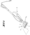
- a vacuum cleaner 1 with an electric motor 2 drivable brush rollers 3 attachment 4th
- the voltage supply of the electric motor 2 takes place via the vacuum cleaner 1.
- This anti-lock circuit 5 is between two poles the motor potential M and the zero potential N switched. Between the performance potential L and the Motor potential M is that which drives the brush rollers 3 Electric motor 2 switched, which via a power controller 6 or via one via the power controller regulated electronics is controlled.
- the circuit 5 initially has one, a first Downstream capacitor C1 and a second capacitor C2 upstream triac T1, where in the exemplary circuit, a first, non-polarized capacitor C1 with a capacity of 100 nanofarads and a second, polarized capacitor C2, for example an electrolytic capacitor with a capacity of 220 microfarads are provided.
- a first diac D1 is connected upstream of the triac T1.
- a resistor R1 is assigned is another Connection to zero potential N is formed, in which Connection is arranged a second diac D6, which second diac D6 is part of an opto-coupler IC1.
- a rectifier D3 is arranged in the form of a diode, this rectifier D3 a resistor R5 is connected downstream.
- control element D7 is in the supply line to second capacitor C2 arranged, with the interposition another resistor R3.
- diac D4 In the motor potential line M there is a third diac D4 arranged. These are a diode D2 and a in series Resistor R4 connected.
- Diode D2 and resistor R4 Downstream of the row arrangement of Diac D4, Diode D2 and resistor R4 are another resistor R6 and an LED parallel to this resistor R6 D5 provided.
- the entire anti-lock circuit 5 is between the Motor potential M and the zero potential N in parallel switched, non-polarized capacitor C3 with an exemplary Capacity of 100 nanofarads connected in parallel.
- the triac T1 is connected through the capacitor C1 and the diac D1 fired at the beginning of each half wave.
- the motor current generates a voltage drop on one, the Triac T1 downstream shunt resistor R8.
- the voltage is rectified via the diode D3 and charges capacitor C2 through resistor R5.
- the opto-coupler (opto-triac) fires IC1. This breaks the voltage across resistor R2 together as a result the Triac T1 locks.
- the delay in the starting current depends on the define resistor R5 and capacitor C2 Time constant.
- the diac D4 prevents the capacitor C2 already charged before reaching the ignition voltage of the Triac T1 becomes.
- an anti-lock circuit 5 is specified, which is logically constructed as a two-pole system. This circuit proves to be insensitive to electrostatic charge.
Landscapes
- Control Of Ac Motors In General (AREA)
- Emergency Protection Circuit Devices (AREA)
- Lock And Its Accessories (AREA)
- Electric Vacuum Cleaner (AREA)
Abstract
Description
- Fig. 1
- einen Elektro-Staubsauger mit einem, elektrisch antreibbare Bürsten aufweisenden Vorsatzgerät;
- Fig. 2
- das Schaltbild der erfindungsgemäßen Blockierschutzschaltung für einen Elektromotor.
Claims (8)
- Blockierschutzschaltung (5) für einen Elektromotor (2), insbesondere einen Elektromotor (2) eines Haushaltsgerätes, wie etwa eines Staubsaugers (1), dadurch gekennzeichnet, daß bei zweipoliger Ausführung zwischen dem Motorpotential (M) und dem Nullpotential (N) nachgeschaltet zu einem ersten Kondensator (C1) und vorgeschaltet zu einem zweiten Kondensator (C2) ein Triac (T1) vorgesehen ist.
- Blockierschutzschaltung nach Anspruch 1 oder insbesondere danach, dadurch gekennzeichnet, daß dem Triac (T1) ein erster Diac (D1) vorgeschaltet ist.
- Blockierschutzschaltung nach einem oder mehreren der vorhergehenden Ansprüche oder insbesondere danach,
dadurch gekennzeichnet, daß vor dem ersten Kondensator
(C1) eine weitere Verbindung zum Nullpotential (N) ausgebildet ist und daß in dieser Verbindung ein zweiter Diac (D6) angeordnet ist. - Blockierschutzschaltung nach einem oder mehreren der vorhergehenden Ansprüche oder insbesondere danach,
dadurch gekennzeichnet, daß zwischen dem Triac (T1) und
dem zweiten Kondensator (C2) ein Gleichrichter (D3) angeordnet ist. - Blockierschutzschaltung nach einem oder mehreren der vorhergehenden Ansprüche oder insbesondere danach,
dadurch gekennzeichnet, daß ein Steuerelement (D7) für
den zweiten Diac (D6) in der Zuleitung zum zweiten Kondensator (C2) angeordnet ist. - Blockierschutzschaltung nach einem oder mehreren der vorhergehenden Ansprüche oder insbesondere danach,
dadurch gekennzeichnet, daß in der Motorpotentialleitung (M) ein dritter Diac (D4) angeordnet ist, zur Verhinderung der Ladung des zweiten Kondensators (C2) vor Erreichen der Zündspannung des Triacs (T1). - Blockierschutzschaltung nach einem oder mehreren der vorhergehenden Ansprüche oder insbesondere danach,
dadurch gekennzeichnet, daß das Steuerelement (D7) ein
optoelektronisches Element ist. - Blockierschutzschaltung nach einem oder mehreren der vorhergehenden Ansprüche oder insbesondere danach,
dadurch gekennzeichnet, daß das Steuerelement (D7) und
der zweite Diac (D6) in einem Opto-Koppler (IC1) angeordnet sind.
Applications Claiming Priority (2)
| Application Number | Priority Date | Filing Date | Title |
|---|---|---|---|
| DE19954659 | 1999-11-13 | ||
| DE19954659A DE19954659A1 (de) | 1999-11-13 | 1999-11-13 | Blockierschutzschaltung für einen Elektromotor |
Publications (3)
| Publication Number | Publication Date |
|---|---|
| EP1104072A2 true EP1104072A2 (de) | 2001-05-30 |
| EP1104072A3 EP1104072A3 (de) | 2004-04-21 |
| EP1104072B1 EP1104072B1 (de) | 2006-08-16 |
Family
ID=7928934
Family Applications (1)
| Application Number | Title | Priority Date | Filing Date |
|---|---|---|---|
| EP00124133A Expired - Lifetime EP1104072B1 (de) | 1999-11-13 | 2000-11-07 | Blockierschutzschalter für einen Elektromotor |
Country Status (4)
| Country | Link |
|---|---|
| EP (1) | EP1104072B1 (de) |
| AT (1) | ATE336818T1 (de) |
| DE (2) | DE19954659A1 (de) |
| ES (1) | ES2265854T3 (de) |
Family Cites Families (2)
| Publication number | Priority date | Publication date | Assignee | Title |
|---|---|---|---|---|
| FR2352424A1 (fr) * | 1976-05-18 | 1977-12-16 | Peugeot Aciers Et Outillage | Dispositif limiteur de courant pour moteur a courant alternatif |
| DE8706788U1 (de) * | 1987-05-12 | 1987-07-02 | Kurz, Gerhard, 7262 Althengstett | Schutzschaltung nach Art einer elektrischen Sicherung für eine Motorsaugbürste bei Staubsaugern u. dgl. |
-
1999
- 1999-11-13 DE DE19954659A patent/DE19954659A1/de not_active Withdrawn
-
2000
- 2000-11-07 EP EP00124133A patent/EP1104072B1/de not_active Expired - Lifetime
- 2000-11-07 AT AT00124133T patent/ATE336818T1/de not_active IP Right Cessation
- 2000-11-07 DE DE50013329T patent/DE50013329D1/de not_active Expired - Lifetime
- 2000-11-07 ES ES00124133T patent/ES2265854T3/es not_active Expired - Lifetime
Also Published As
| Publication number | Publication date |
|---|---|
| ATE336818T1 (de) | 2006-09-15 |
| EP1104072B1 (de) | 2006-08-16 |
| DE50013329D1 (de) | 2006-09-28 |
| EP1104072A3 (de) | 2004-04-21 |
| ES2265854T3 (es) | 2007-03-01 |
| DE19954659A1 (de) | 2001-05-17 |
Similar Documents
| Publication | Publication Date | Title |
|---|---|---|
| DE69428866T2 (de) | Vorschaltgerät für eine Entladungslampe, mit Arbeitsfähigkeitsanzeige | |
| DE3612147C2 (de) | ||
| DE2539253A1 (de) | Netzgeraet mit schaltendem regler | |
| DE3503083A1 (de) | Staubsauger mit aufwirbelvorrichtung | |
| DE3805510A1 (de) | Schaltungsanordnung zum betrieb einer niederdruckentladungslampe | |
| CH660266A5 (de) | Thyristoreinrichtung mit durch licht steuerbaren thyristoren. | |
| EP0326220B1 (de) | Schaltungsanordnung zur Speisung einer Last | |
| DE2362471C2 (de) | Unterbrecherloses Zündsystem für Brennkraftmaschinen, insbesondere in Kraftfahrzeugen | |
| EP0146683A1 (de) | Wechselrichter | |
| EP0116302A2 (de) | Umrichter | |
| EP1943726B1 (de) | Elektronische gleichspannungs-zwischenschaltung | |
| DE68911989T2 (de) | Taktregler. | |
| EP1104072B1 (de) | Blockierschutzschalter für einen Elektromotor | |
| DE2233152A1 (de) | Kurzschlusschutzschaltung fuer leistungsschaltungen | |
| DE69015696T2 (de) | Vorrichtung zum Ausserbetriebsetzen eines Motors. | |
| EP0205730B1 (de) | Sicherheitseinrichtung für ein elektromotorisch angetriebenes Werkzeug | |
| DE602004011536T2 (de) | Leistungsregler | |
| CH626199A5 (de) | ||
| DE2720503A1 (de) | Elektrische sicherheitsschaltung | |
| EP0057896B2 (de) | Schaltungsanordnung für den Betrieb eines elektromagnetisch angetriebenen Schlaggerätes | |
| DE1208803B (de) | Einrichtung zur Zwangskommutierung fuer einen gleichstromgespeisten Motor mit elektronischem Stromwender | |
| DE3041840C2 (de) | Zweidraht-Speiseschaltung | |
| DE4304690C1 (de) | Elektronische Anlauf-Sicherheitsschaltung für den motorischen Antrieb eines Elektrogerätes | |
| DE19755368B4 (de) | Startvorrichtung für einen Elektromotor | |
| DE2502115A1 (de) | Gasentladungslampen-leuchte |
Legal Events
| Date | Code | Title | Description |
|---|---|---|---|
| PUAI | Public reference made under article 153(3) epc to a published international application that has entered the european phase |
Free format text: ORIGINAL CODE: 0009012 |
|
| AK | Designated contracting states |
Kind code of ref document: A2 Designated state(s): AT BE CH CY DE DK ES FI FR GB GR IE IT LI LU MC NL PT SE TR |
|
| AX | Request for extension of the european patent |
Free format text: AL;LT;LV;MK;RO;SI |
|
| PUAL | Search report despatched |
Free format text: ORIGINAL CODE: 0009013 |
|
| AK | Designated contracting states |
Kind code of ref document: A3 Designated state(s): AT BE CH CY DE DK ES FI FR GB GR IE IT LI LU MC NL PT SE TR |
|
| AX | Request for extension of the european patent |
Extension state: AL LT LV MK RO SI |
|
| 17P | Request for examination filed |
Effective date: 20040817 |
|
| AKX | Designation fees paid |
Designated state(s): AT DE ES FR IT |
|
| 17Q | First examination report despatched |
Effective date: 20041027 |
|
| GRAP | Despatch of communication of intention to grant a patent |
Free format text: ORIGINAL CODE: EPIDOSNIGR1 |
|
| GRAS | Grant fee paid |
Free format text: ORIGINAL CODE: EPIDOSNIGR3 |
|
| GRAA | (expected) grant |
Free format text: ORIGINAL CODE: 0009210 |
|
| AK | Designated contracting states |
Kind code of ref document: B1 Designated state(s): AT DE ES FR IT |
|
| PG25 | Lapsed in a contracting state [announced via postgrant information from national office to epo] |
Ref country code: IT Free format text: LAPSE BECAUSE OF FAILURE TO SUBMIT A TRANSLATION OF THE DESCRIPTION OR TO PAY THE FEE WITHIN THE PRESCRIBED TIME-LIMIT;WARNING: LAPSES OF ITALIAN PATENTS WITH EFFECTIVE DATE BEFORE 2007 MAY HAVE OCCURRED AT ANY TIME BEFORE 2007. THE CORRECT EFFECTIVE DATE MAY BE DIFFERENT FROM THE ONE RECORDED. Effective date: 20060816 |
|
| REF | Corresponds to: |
Ref document number: 50013329 Country of ref document: DE Date of ref document: 20060928 Kind code of ref document: P |
|
| ET | Fr: translation filed | ||
| REG | Reference to a national code |
Ref country code: ES Ref legal event code: FG2A Ref document number: 2265854 Country of ref document: ES Kind code of ref document: T3 |
|
| PLBE | No opposition filed within time limit |
Free format text: ORIGINAL CODE: 0009261 |
|
| STAA | Information on the status of an ep patent application or granted ep patent |
Free format text: STATUS: NO OPPOSITION FILED WITHIN TIME LIMIT |
|
| 26N | No opposition filed |
Effective date: 20070518 |
|
| PGFP | Annual fee paid to national office [announced via postgrant information from national office to epo] |
Ref country code: ES Payment date: 20091109 Year of fee payment: 10 Ref country code: AT Payment date: 20091109 Year of fee payment: 10 |
|
| PGFP | Annual fee paid to national office [announced via postgrant information from national office to epo] |
Ref country code: IT Payment date: 20091126 Year of fee payment: 10 Ref country code: FR Payment date: 20091120 Year of fee payment: 10 |
|
| PGFP | Annual fee paid to national office [announced via postgrant information from national office to epo] |
Ref country code: DE Payment date: 20091204 Year of fee payment: 10 |
|
| REG | Reference to a national code |
Ref country code: FR Ref legal event code: ST Effective date: 20110801 |
|
| PG25 | Lapsed in a contracting state [announced via postgrant information from national office to epo] |
Ref country code: AT Free format text: LAPSE BECAUSE OF NON-PAYMENT OF DUE FEES Effective date: 20101107 |
|
| REG | Reference to a national code |
Ref country code: DE Ref legal event code: R119 Ref document number: 50013329 Country of ref document: DE Effective date: 20110601 Ref country code: DE Ref legal event code: R119 Ref document number: 50013329 Country of ref document: DE Effective date: 20110531 |
|
| PG25 | Lapsed in a contracting state [announced via postgrant information from national office to epo] |
Ref country code: DE Free format text: LAPSE BECAUSE OF NON-PAYMENT OF DUE FEES Effective date: 20110531 |
|
| PG25 | Lapsed in a contracting state [announced via postgrant information from national office to epo] |
Ref country code: FR Free format text: LAPSE BECAUSE OF NON-PAYMENT OF DUE FEES Effective date: 20101130 |
|
| PG25 | Lapsed in a contracting state [announced via postgrant information from national office to epo] |
Ref country code: IT Free format text: LAPSE BECAUSE OF NON-PAYMENT OF DUE FEES Effective date: 20101107 |
|
| REG | Reference to a national code |
Ref country code: ES Ref legal event code: FD2A Effective date: 20120110 |
|
| PG25 | Lapsed in a contracting state [announced via postgrant information from national office to epo] |
Ref country code: ES Free format text: LAPSE BECAUSE OF NON-PAYMENT OF DUE FEES Effective date: 20101108 |