EP1104070A2 - Power generation system, and method for installing the same - Google Patents
Power generation system, and method for installing the same Download PDFInfo
- Publication number
- EP1104070A2 EP1104070A2 EP00125991A EP00125991A EP1104070A2 EP 1104070 A2 EP1104070 A2 EP 1104070A2 EP 00125991 A EP00125991 A EP 00125991A EP 00125991 A EP00125991 A EP 00125991A EP 1104070 A2 EP1104070 A2 EP 1104070A2
- Authority
- EP
- European Patent Office
- Prior art keywords
- phase
- power generation
- generation system
- ground
- earth leakage
- Prior art date
- Legal status (The legal status is an assumption and is not a legal conclusion. Google has not performed a legal analysis and makes no representation as to the accuracy of the status listed.)
- Granted
Links
Images


Classifications
-
- H—ELECTRICITY
- H02—GENERATION; CONVERSION OR DISTRIBUTION OF ELECTRIC POWER
- H02H—EMERGENCY PROTECTIVE CIRCUIT ARRANGEMENTS
- H02H3/00—Emergency protective circuit arrangements for automatic disconnection directly responsive to an undesired change from normal electric working condition with or without subsequent reconnection ; integrated protection
- H02H3/26—Emergency protective circuit arrangements for automatic disconnection directly responsive to an undesired change from normal electric working condition with or without subsequent reconnection ; integrated protection responsive to difference between voltages or between currents; responsive to phase angle between voltages or between currents
- H02H3/32—Emergency protective circuit arrangements for automatic disconnection directly responsive to an undesired change from normal electric working condition with or without subsequent reconnection ; integrated protection responsive to difference between voltages or between currents; responsive to phase angle between voltages or between currents involving comparison of the voltage or current values at corresponding points in different conductors of a single system, e.g. of currents in go and return conductors
- H02H3/33—Emergency protective circuit arrangements for automatic disconnection directly responsive to an undesired change from normal electric working condition with or without subsequent reconnection ; integrated protection responsive to difference between voltages or between currents; responsive to phase angle between voltages or between currents involving comparison of the voltage or current values at corresponding points in different conductors of a single system, e.g. of currents in go and return conductors using summation current transformers
- H02H3/337—Emergency protective circuit arrangements for automatic disconnection directly responsive to an undesired change from normal electric working condition with or without subsequent reconnection ; integrated protection responsive to difference between voltages or between currents; responsive to phase angle between voltages or between currents involving comparison of the voltage or current values at corresponding points in different conductors of a single system, e.g. of currents in go and return conductors using summation current transformers avoiding disconnection due to reactive fault currents
-
- H—ELECTRICITY
- H02—GENERATION; CONVERSION OR DISTRIBUTION OF ELECTRIC POWER
- H02H—EMERGENCY PROTECTIVE CIRCUIT ARRANGEMENTS
- H02H7/00—Emergency protective circuit arrangements specially adapted for specific types of electric machines or apparatus or for sectionalised protection of cable or line systems, and effecting automatic switching in the event of an undesired change from normal working conditions
- H02H7/26—Sectionalised protection of cable or line systems, e.g. for disconnecting a section on which a short-circuit, earth fault, or arc discharge has occured
- H02H7/30—Staggered disconnection
-
- Y—GENERAL TAGGING OF NEW TECHNOLOGICAL DEVELOPMENTS; GENERAL TAGGING OF CROSS-SECTIONAL TECHNOLOGIES SPANNING OVER SEVERAL SECTIONS OF THE IPC; TECHNICAL SUBJECTS COVERED BY FORMER USPC CROSS-REFERENCE ART COLLECTIONS [XRACs] AND DIGESTS
- Y02—TECHNOLOGIES OR APPLICATIONS FOR MITIGATION OR ADAPTATION AGAINST CLIMATE CHANGE
- Y02E—REDUCTION OF GREENHOUSE GAS [GHG] EMISSIONS, RELATED TO ENERGY GENERATION, TRANSMISSION OR DISTRIBUTION
- Y02E10/00—Energy generation through renewable energy sources
- Y02E10/50—Photovoltaic [PV] energy
- Y02E10/56—Power conversion systems, e.g. maximum power point trackers
-
- Y—GENERAL TAGGING OF NEW TECHNOLOGICAL DEVELOPMENTS; GENERAL TAGGING OF CROSS-SECTIONAL TECHNOLOGIES SPANNING OVER SEVERAL SECTIONS OF THE IPC; TECHNICAL SUBJECTS COVERED BY FORMER USPC CROSS-REFERENCE ART COLLECTIONS [XRACs] AND DIGESTS
- Y10—TECHNICAL SUBJECTS COVERED BY FORMER USPC
- Y10S—TECHNICAL SUBJECTS COVERED BY FORMER USPC CROSS-REFERENCE ART COLLECTIONS [XRACs] AND DIGESTS
- Y10S136/00—Batteries: thermoelectric and photoelectric
- Y10S136/291—Applications
- Y10S136/293—Circuits
Definitions
- the present invention relates to a power generation system, and more particularly, to a power generation system which can prevent an unnecessary operation due to an accident of external grounding.
- FIG. 9 is a schematic diagram illustrating conventional connection between a solar power generation system and a low-voltage distribution system.
- A represents a consumer having a solar power generation system, which includes a solar-cell array 1, a system interconnection inverter 2, and a receiving-end earth leakage breaker 3.
- the solar-cell array 1, serving as a DC power supply includes solar-cell modules interconnected in series and/or in parallel so as to provide desired voltage and current.
- the solar-cell array 1 is connected to the system interconnection inverter 2, which is connected to a low-voltage distribution system 4 via the receiving-end earth leakage breaker 3.
- a load 5 is connected between the system interconnection inverter 2 and the receiving-end earth leakage breaker 3.
- DC electric power from the solar-cell array 1 is input to the system interconnection inverter 2 in order to be converted into an AC electric power, which is output to the load 5 or the low-voltage distribution system 4.
- Wiring within the consumer A is provided from the receiving-end earth leakage breaker 3 to the system interconnection inverter 2 and to the load 5.
- the receiving-end earth leakage breaker 3 detects an accident of grounding by detecting a ground current, and disconnects connection between the inside and the outside of the consumer A so that the accident of grounding does not influence the low-voltage distribution system 4 at the outside of the consumer A.
- the solar-cell array 1 Since the solar-cell array 1 has a large area, an earth floating capacitance 6 is present. Recently, solar-cell modules integrated with a building material, or thin solar-cell modules have been developed as solar-cell modules constituting the solar-cell array 1. Sometimes, a conductive member (a metal plate or the like) is used as a reinforcing material or a substrate material for such a solar-cell module. In such a case, a solar-cell array sometimes faces a metal plate with a short distance and a large area, thereby increasing the earth floating capacitance 6. Particularly when the metal plate is grounded, the solar-cell array has a stable earth floating capacitance. Furthermore, if, for example, water from rain adheres to the surface of the solar-cell array, the earth floating capacitance 6 is sometimes generated via the water.
- a conductive member a metal plate or the like
- the system interconnection inverter 2 mostly adopts a transformerless system in which an insulating transformer is not provided.
- the above-described problems are not limited to the solar power generation system.
- the same problems also arise if the earth floating capacitance is large.
- the reception-end earth leakage breaker unnecessarily operates due to an accident of external grounding and electric power supply fails within a consumer.
- the present invention which achieves these objectives relates to a power generation system including a DC power supply connected to a low-voltage distribution system to which a plurality of consumers, each having an earth leakage breaker, are connected and one wire of which is grounded, via a receiving-end earth leakage breaker, and including at least a transformerless inverter and an earth floating capacitance.
- An operational time limit of the receiving-end earth leakage breaker of the power generation system is set to a value larger than an operational time limit of the earth leakage breakers provided in the consumers.
- the present invention which achieves these objectives relates to a power generation system including a DC power supply connected to a low-voltage distribution system one wire of which is grounded, via a receiving-end earth leakage breaker, and including at least a transformerless inverter and an earth floating capacitance.
- the system also includes ground-direction determination means for determining whether a grounded position is inside or outside the power generation system.
- the present invention which achieves these objectives relates to a power generation system including a DC power supply connected to a low-voltage distribution system one wire of which is grounded, via a receiving-end earth leakage breaker, and including at least a transformerless inverter and an earth floating capacitance.
- the receiving-end earth leakage breaker includes voltage-to-ground detection means, a zero-phase current transformer, zero-phase-current detection means connected to the zero-phase current transformer, phase comparison means connected to the voltage-to-ground detection means and the zero-phase-current detection means, a time-limit selector, connected to the phase comparison means, for selecting a different time limit in accordance with a signal output from the phase comparison means, zero-phase-current-level determination means connected to the zero-phase-current detection means, and contact driving means, connected to the zero-phase-current-level determination means and the time-limit selector, for driving a contact in accordance with an output of each of the zero-phase-current-level determination means and the time-limit selector.
- the present invention which achieves these objectives relates to a power generation system including a DC power supply connected to a low-voltage distribution system one wire of which is grounded, via a receiving-end earth leakage breaker, and including at least a transformerless inverter and an earth floating capacitance.
- the receiving-end earth leakage breaker includes voltage-to-ground detection means, voltage-to-ground-level determination means connected to the voltage-to-ground detection means, a zero-phase current transformer, zero-phase-current detection means connected to the zero-phase current transformer, zero-phase-current level determination means connected to the zero-phase-current detection means, and contact driving means, connected to the zero-phase-current-level determination means and the voltage-to-ground-level determination means, for driving a contact in accordance with an output of each of the zero-phase-current-level determination means and the voltage-to-ground-level determination means.
- the present invention which achieves these objectives relates to a power generation system including a DC power supply connected to a low-voltage distribution system one wire of which is grounded, via a receiving-end earth leakage breaker, and including at least a transformerless inverter and an earth floating capacitance.
- the receiving-end earth leakage breaker includes voltage-to-ground detection means, voltage-to-ground-level determination means connected to the voltage-to-ground detection means, a time-limit selector, connected to the voltage-to-ground-level determination means, for selecting a time limit in accordance with an output of the voltage-to-ground detection means, a zero-phase current transformer, zero-phase-current detection means connected to the zero-phase current transformer, zero-phase-current-level determination means connected to the zero-phase-current detection means, and contact driving means, connected to the zero-phase-current-level determination means and the time-limit selector, for driving a contact in accordance with an output of each of the zero-phase-current-level determination means and the time-limit selector.
- the present invention which achieves these objectives relates to a power-generation-system installing method including the step of connecting a power generation system including a DC power supply, including at least a transformerless inverter and an earth floating capacitance, to a low-voltage distribution system to which a plurality of consumers, each having an earth leakage breaker, are connected and one wire of which is grounded, via a receiving-end earth leakage breaker.
- An operation time of the receiving-end earth leakage breaker is set to a value larger than an operational time limit of the earth leakage breakers provided in the consumers.
- the present invention which achieves these objectives relates to a power-generation-system installing method including the step of connecting a power generation system including a DC power supply, including at least a transformerless inverter and an earth floating capacitance, to a low-voltage distribution system one wire of which is grounded, via a receiving-end earth leakage breaker.
- ground-direction determination means for determining whether a ground position is inside or outside the power generation system is provided.
- a power generation system is preferably connected to a low-voltage distribution system including a single-phase low-voltage distribution system and a three-phase distribution system which are commonly grounded.
- the power generation system preferably operates such that a time until a receiving-end earth leakage breaker operates when ground-direction determination means has determined that a grounded position is inside the system is shorter than a time until the receiving-end earth leakage breaker operates when the ground-direction determination means has determined that the grounded position is outside the system, and such that the receiving-end earth leakage breaker operates when the ground-direction determination means has determined that the grounded position is inside the system, and the receiving-end earth leakage breaker does not operate when the ground-direction determination means has determined that the grounded position is outside the system.
- the ground-direction determination means preferably determines whether the grounded position is inside or outside the system, from a phase difference between a voltage to ground of a ground-side terminal of the low-voltage distribution system and a zero-phase current.
- ground-direction determination means for determining that the grounded position is outside the system when a voltage to ground of a ground-side terminal of the single-phase distribution system is higher than a normal value in the single-phase system is preferably used.
- a DC power supply preferably includes solar cells.
- the solar cell preferably includes a solar-cell element and a metal plate.
- the metal plate is preferably grounded.
- a DC power supply configured by a solar-cell array in which a plurality of solar cells are connected in series and/or in parallel is preferably used in the present invention.
- the first embodiment has the feature that the objects of the present invention can be substantially achieved very easily and inexpensively.
- a receiving-end earth leakage breaker (hereinafter abbreviated as an "earth leakage breaker") is provided in each of consumers other than a consumer having a power generation system.
- the earth leakage breaker operates with an appropriate response speed (mostly within 0.1 second), and electric power supply from the low-voltage distribution system to the consumer is disconnected.
- the essential technical concept of the first embodiment is that at that time, disconnection of electric power supply due to leakage in other consumers is prevented by prohibiting the earth leakage breaker of the consumer having the power generation system to operate for a small amount of time.
- FIG. 1 is a schematic diagram illustrating a preferred example of connection between the power generation system and the low-voltage distribution system according to the first embodiment.
- the DC power supply of the power generation system of the present invention is not limited to a specific type, provided that it has an earth floating capacitance. However, as will be described later, a power supply including a solar cell is preferable as the DC power supply.
- a solar-cell array 1 preferably used as the DC power supply of the present invention may have various configurations. Although a single solar cell may, of course, be used as the DC power supply instead of the array, a solar-cell array including a plurality of solar cells is suitable for obtaining large electric power. Any solar-cell array may be used as the solar-cell array 1, provided that it has an earth floating capacitance 6, and the type of solar cell modules constituting the solar-cell array 1 is not limited to a specific type. The effects of the present invention are more pronounced as the earth floating capacitance 6 is larger.
- the effects of the present invention are particularly pronounced when the solar-cell array 1 is configured, for example, by solar-cell modules in each of which a solar cell (element) is subjected to resin sealing on a metal reinforcing plate, solar-cell modules, each formed so as to contact a metal plate, or solar-cell modules integrally formed with a building material.
- the effects of the present invention may also be obtained when using a solar-cell array including solar-cell modules whose earth floating capacitance 6 is usually small but increases by rain or the like.
- the metal reinforcing plate, the metal plate or the like which has been described above is grounded, since a stable earth floating capacitance is present, unnecessary disconnection tends to occur, so that the effects of the present invention can be pronouncedly obtained.
- the range of the earth floating capacitance with which the effects of the present invention are pronounced is at least 0.1 ⁇ F. There is no limit for the earth floating capacitance because theoretically, the leakage current is larger as the capacitance is larger.
- an array of 3.6 kWp was formed by using 60 (15 in series and 4 in parallel) solar-cell modules, each having a metal plate as the substrate (made by Canon Inc., product type BS2-01, with a rated output of 60 Wp (watt peak)). All of the substrate metal plates are grounded.
- the measured value of the earth floating capacitance at that time was 2.4 ⁇ F.
- the capacitance of a filter capacitor within the inverter, and the like are, of course, included in the earth floating capacitance 6. The point is that the electrostatic capacitance of the DC circuit with respect to the ground causes a problem.
- An inverter 2 is a transformerless inverter.
- Various types of transformerless inverters may be used.
- the present invention is made in consideration of the occurrence of penetration of an external ground current in a power generation system in which a non-insulating inverter and a DC power supply having a floating capacitance are combined.
- a transformerless inverter is indispensable for providing such a situation.
- a transformerless inverter made by Japan Storage Battery Co., Ltd. type LINEBACK FX
- a low-voltage distribution system one wire of which is grounded may be used as a low-voltage distribution system 4.
- a single-phase three-wire distribution system with a voltage of 100 V/200 V and a frequency of 60 Hz is used.
- Any load may be used as a load 5, provided that it consumes electric power.
- an ordinary electric appliance may be used.
- a 1 kW electric radiant heater was used as the load 5.
- Such heaters were installed in the consumers A, B1 and B2.
- An earth leakage breaker incorporating operational-time-limit setting means 7 is adopted as an earth leakage breaker 3A used in the power generation system. Since many such earth leakage breakers are commercially available, one of such breakers may be used.
- the operational current of the breaker 3A is 30 mA.
- the operational-time-limit setting means 7 may, of course, be separately provided. Any one of various known digital or analog techniques may be used for setting an operational time limit.
- an earth leakage breaker having a rated operational current of 30 mA and an operational time limit equal to or less than 0.1 second was selected as an earth leakage breaker 3 of another consumer B1 or B2, because an earth leakage breaker with a sensitivity and an operational current having values close to the above-described ones is mostly used in ordinary homes.
- the essential technical concept of the first embodiment is that disconnection of power supply due to leakage in another consumer is prevented by causing an earth leakage breaker of a consumer having a power generation system not to operate for a small time period.
- the operational time limit of the earth leakage breaker 3A of the power generation system was set to 0.8 second which is larger than the operational time limit of the earth leakage breakers 3 of the other consumers B1 and B2.
- the operational time limit of the earth leakage breaker 3A is preferably as short as possible within a range of achievement of the objects of the present invention. More specifically, the operational time limit is preferably set to a value equal to or larger than 0.1 second and equal to or less than 1.0 second.
- the time limit may be changed by changing the rated operational current instead of directly changing the delay time limit.
- This approach utilizes the fact that, when leakage currents having the same magnitude flow, an earth leakage breaker having a larger rated operational current (having a smaller sensitivity) operates slower. That is, it is only necessary to set the rated operational current of the earth leakage breaker 3A of the power generation system to a value larger than the rated operational current of the earth leakage breakers 3 of the consumers B1 and B2. However, it is preferable to prevent an extreme decrease in the sensitivity. More specifically, the rated operational current of the earth leakage breaker 3A is preferably set to a value equal to or larger than 100 mA and equal to or less than 1,000 mA.
- ground-direction determination means for determining whether or not grounding has occurred outside a power generation system, in a function of detecting grounding of the system.
- FIG. 9 illustrates a pseudo-equivalent circuit at that time.
- a ground current Ig0 generated due to a ground resistance Rx of the consumer B2 is divided into a current Igl flowing through a B-type grounding resistance Rb which is originally to flow, and current Ig2 flowing through a series circuit including a D-type grounding resistance Rd and an earth floating capacitance C (when the substrate metal plate of the solar cell module is subjected to D-type grounding).
- the great feature of the second embodiment is to control the operation of the earth leakage breaker by determining whether grounding has occurred outside or inside the consumer A by detecting the penetrating ground current Ig2.
- FIG. 2 is a schematic diagram illustrating a preferred example of connection between a power generation system and a low-voltage distribution system according to the second embodiment.
- A represents a consumer having a solar power generation system
- an earth leakage breaker 3B in the power generation system includes ground-direction determination means 8A.
- a solar-cell array 1, a system interconnection inverter 2, a low-voltage distribution system 4, a load 5, and earth leakage breakers 3 used in consumers B1 and B2 are the same as those in the first embodiment.
- the earth leakage breaker 3B used in the second embodiment includes the ground-direction determination means 8A.
- the ground-direction determination means 8A may be incorporated within the earth leakage breaker 3B as shown in FIG. 2, or may be provided separately from the earth leakage breaker 3B.
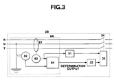
- FIG. 3 is a schematic block diagram illustrating the configuration of the earth leakage breaker 3B.
- the ground-direction determination means 8A includes voltage-to-ground detection means 82, a zero-phase current transformer 81, zero-phase-current detection means 83, and phase comparison means 84.
- the ground-direction determination means 8A determines that grounding has occurred outside the consumer A (external grounding) when the phase of the voltage to ground with reference to the zero-phase current is within a fixed phase range, determines that grounding has occurred inside the consumer A (internal grounding) when the phase of the voltage to ground is not within the fixed range, and outputs the result of the determination.
- the range for determining external grounding can be narrower around - 90 degrees (for example, 90 degrees ⁇ 30 degrees).
- Various types of voltage detection means, current detection means and phase comparison means which can be used for the above-described purpose are commercially available as signal transducers, in which known techniques can be used.
- the result of determination output from the phase comparison means 84 is transmitted to a time-limit selector 32 in order to select a time limit. More specifically, a time limit of 0.8 seconds is selected when it has been determined that external grounding has occurred, and 0.1 second is selected when it has been determined that internal grounding has occurred.
- the result of the selection of the time limit is transmitted to contact driving means 33 together with the result of determination of zero-phase-current-level determination means 31 (having a determination level of 30 mA), in order to operate a contact 34.
- the receiving-end earth leakage breaker of the second embodiment can perform very precise determination of internal or external grounding, and need not reduce the response speed when internal grounding occurs. In other words, when internal grounding occurs, the receiving-end earth leakage breaker of the second embodiment operates entirely in the same manner as an ordinary receiving-end earth leakage breaker, and therefore has high safety.
- FIG. 6 illustrates a vector diagram when a three-phase system subjected to ⁇ connection and a single-phase three-wire system are commonly grounded as shown in FIG. 4.
- the present invention can provide larger effects when the power generation system is connected to a low-voltage distribution system having a commonly grounded conductor as in the above-described case. Such an example of common grounding is considered to be peculiar to a power generation system connected to a low-voltage distribution system.
- a solar-cell array 1, an inverter 2, a load 5, and receiving-end earth leakage breakers 3 of consumers B1 and B2 have the same configuration as in the first embodiment. Further description will be omitted for the same components as those described in the second embodiment.
- a system in which a single-phase three-wire system and a three-phase system are commonly distributed from a three-phase transformer as shown in FIG. 4 is used as a low-voltage distribution system.
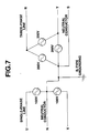
- Two systems having a common grounded point for example, systems in which each system individually has a transformer as shown in FIG. 7, or modified V connection in which two single-phase transformers are combined, may also be applied to the third embodiment instead of the above-described configuration.
- Direction determination means 8B which is simpler than in the second embodiment may be utilized as a breaker 3C used in the third embodiment.
- FIG. 5 schematically illustrates such breaker 3C and direction determination means 8B. More specifically, in the case of FIG. 5, an output level of voltage-to-ground detection means 82 is determined voltage-to-ground-level determination means 85. That is, in the third embodiment, whether external grounding or internal grounding occurs is determined by determining only a voltage to ground of a neutral (N) conductor.
- N neutral
- the determination means 85 determines that internal grounding has occurred when the output of the voltage-to-ground detection means 82 is lower than a preset voltage threshold, and determines that external grounding has occurred when the output of the voltage-to-ground detection means 82 is higher than the preset voltage threshold.
- the determination output is transmitted to a time-limit selector 32 in order to select a time limit.
- the result of selection of the time limit is transmitted to contact driving means 33 together with a result of determination of zero-phase-current-level determination means 31, in order to operate a contact 34. It is convenient to set the voltage threshold so that it is determined that external grounding has occurred when a voltage higher than the voltage of a system where the power generation system is connected is detected.
- the voltage threshold is set to 110 V.
- direction is determined by comparing phases.
- direction is determined by detecting the voltage. Accordingly, the third embodiment has features in that the configuration is simplified and the cost is lower.
- Grounding (500 mA with 0.1 second) of the S phase was generated in the consumer B2. It was confirmed that the potential to ground was raised to about 130 V, and no unnecessary disconnection of electric power supply (an unnecessary operation of the earth leakage breaker) did not occur. However, unnecessary disconnection of electric power supply occurred when grounding of the R phase or the T phase which is common to the single-phase distribution system was generated. This is because the potential to ground is not raised to 110 V in such a case. Such unnecessary disconnection of electric power supply can be prevented by increasing the operational time limit of the earth leakage breaker 3C by providing the same time-limit selector 32 as in the second embodiment.
- the optimum system for determining direction using the voltage to ground as in the third embodiment corresponds to a case in which, as shown in FIG. 7, each of a single-phase system and a three-phase system individually has a transformer and one wire of each of the systems is commonly grounded.
- the potential to ground is raised even when grounding occurs in the R phase or the T phase, so that it is possible to determine whether internal grounding or external grounding has occurred. That is, in the case shown in FIG. 7, the time-limit selector 32 is unnecessary.
- the neutral conductor S phase and N phase are originally grounded, it is generally unnecessary to detect grounding in these phases.
- the present invention has the following pronounced effects.
Abstract
Description
Claims (24)
- A power generation system comprising:a DC power supply connected to a low-voltage distribution system to which a plurality of consumers, each having an earth leakage breaker, are connected and one wire of which is grounded, via a receiving-end earth leakage breaker, and comprising at least a transformerless inverter and an earth floating capacitance,wherein an operational time limit of the receiving-end earth leakage breaker of said power generation system is set to a value larger than an operational time limit of the earth leakage breakers provided in the consumers.
- A power generation system according to Claim 1, wherein the low-voltage distribution system comprises a single-phase low-voltage distribution system and a three-phase distribution system which are commonly grounded.
- A power generation system comprising:a DC power supply connected to a low-voltage distribution system one wire of which is grounded, via a receiving-end earth leakage breaker, and comprising at least a transformerless inverter and an earth floating capacitance; andground-direction determination means for determining whether a grounded position is inside or outside said power generation system.
- A power generation system according to Claim 3, wherein a time until the receiving-end earth leakage breaker operates when said ground-direction determination means has determined that the grounded position is inside said power generation system is shorter than a time until said receiving-end earth leakage breaker operates when said ground-direction determination means has determined that the grounded position is outside said power generation system.
- A power generation system according to Claim 3, wherein the receiving-end earth leakage breaker operates when said ground-direction determination means has determined that the grounded position is within said power generation system, and the receiving-end earth leakage breaker does not operate when said ground-direction determination means has determined that the grounded position is outside said power generation system.
- A power generation system according to Claim 3, wherein the low-voltage distribution system comprises a single-phase low-voltage distribution system and a three-phase distribution system which are commonly grounded.
- A power generation system according to Claim 3, wherein said ground-direction determination means determines whether the grounded position is inside or outside said power generation system from a phase difference between a voltage to ground of a grounded-side terminal of the low-voltage distribution system and a zero-phase current.
- A power generation system according to Claim 6, wherein said transformerless inverter is connected to the single-phase distribution system, and wherein said ground-direction determination means determines that the grounded position is outside said power generation system when a voltage to ground of a grounded-side terminal of the single-phase distribution system is higher than a normal value in the single-phase distribution system.
- A power generation system according to any one of Claims 1 through 8, wherein said DC power supply comprises a solar cell.
- A power generation system according to Claim 9, wherein said solar cell comprises solar-cell modules, each comprising a solar-cell element and a metal plate.
- A power generation system according to Claim 10, wherein said metal plate is grounded.
- A power generation system according to Claim 9, wherein said DC power supply comprises a solar-cell array in which a plurality of solar cells are connected in series and/or in parallel.
- A power generation system comprising:
a DC power supply connected to a low-voltage distribution system one wire of which is grounded, via a receiving-end earth leakage breaker, and comprising at least a transformerless inverter and an earth floating capacitance, said receiving-end earth leakage breaker comprising:voltage-to-ground detection means;a zero-phase current transformer;zero-phase-current detection means connected to said zero-phase current transformer;phase comparison means connected to said voltage-to-ground detection means and said zero-phase-current detection means;a time-limit selector, connected to said phase comparison means, for selecting a different time limit in accordance with a signal output from said phase comparison means;zero-phase-current-level determination means connected to said zero-phase-current detection means; andcontact driving means, connected to said zero-phase-current-level determination means and said time-limit selector, for driving a contact in accordance with an output of each of said zero-phase-current-level determination means and said time-limit selector. - A power generation system comprising:
a DC power supply connected to a low-voltage distribution system one wire of which is grounded, via a receiving-end earth leakage breaker, and comprising at least a transformerless inverter and an earth floating capacitance, said receiving-end earth leakage breaker comprising:voltage-to-ground detection means;voltage-to-ground-level determination means connected to said voltage-to-ground detection means;a zero-phase current transformer;zero-phase-current detection means connected to said zero-phase current transformer;zero-phase-current-level determination means connected to said zero-phase-current detection means; andcontact driving means, connected to said zero-phase-current-level determination means and said voltage-to-ground-level determination means, for driving a contact in accordance with an output of each of said zero-phase-current-level determination means and said voltage-to-ground-level determination means. - A power generation system comprising:
a DC power supply connected to a low-voltage distribution system one wire of which is grounded, via a receiving-end earth leakage breaker, and comprising at least a transformerless inverter and an earth floating capacitance, said receiving-end earth leakage breaker comprising:voltage-to-ground detection means;voltage-to-ground-level determination means connected to said voltage-to-ground detection means;a time-limit selector, connected to said voltage-to-ground-level determination means, for selecting a time limit in accordance with an output of said voltage-to-ground detection means;a zero-phase current transformer;zero-phase-current detection means connected to said zero-phase current transformer;zero-phase-current-level determination means connected to said zero-phase-current detection means; andcontact driving means, connected to said zero-phase-current-level determination means and said time-limit selector, for driving a contact in accordance with an output of each of said zero-phase-current-level determination means and said time-limit selector. - A power-generation-system installing method comprising the step ofconnecting a power generation system including a DC power supply, including at least a transformerless inverter and an earth floating capacitance, to a low-voltage distribution system to which a plurality of consumers, each having an earth leakage breaker, are connected and one wire of which is grounded, via a receiving-end earth leakage breaker,wherein an operation time of the receiving-end earth leakage breaker is set to a value larger than an operational time limit of the earth leakage breakers provided in the consumers.
- A power-generation-system installing method comprising the step ofconnecting a power generation system including a DC power supply, including at least a transformerless inverter and an earth floating capacitance, to a low-voltage distribution system one wire of which is grounded, via a receiving-end earth leakage breaker,wherein ground-direction determination means for determining whether a grounded position is inside or outside the power generation system is provided.
- A method according to Claim 17, wherein control means for performing control such that a time until the receiving-end earth leakage breaker operates when the ground-direction determination means has determined that the grounded position is inside the power generation system is shorter than a time until the receiving-end earth leakage breaker operates when the ground-direction determination means has determined that the grounded position is outside the power generation system is provided.
- A method according to Claim 17, wherein control means for performing control such that the receiving-end earth leakage breaker operates when the ground-direction determination means has determined that the grounded position is within the power generation system, and the receiving-end earth leakage breaker does not operate when the ground-direction determination means has determined that the grounded position is outside the power generation system is provided.
- A method according to Claim 17, wherein ground-direction determination means for determining whether the grounded position is inside or outside the power generation system, from a phase difference between a voltage to ground of a grounded-side terminal of the low-voltage distribution system and a zero-phase current is used as the ground-direction determination means.
- A method according to any one of Claims 15 through 20, wherein a power supply including a solar cell is provided as the DC power supply.
- A method according to Claim 21, wherein solar-cell modules, each including a solar-cell element and a metal plate, are used for the solar cell.
- A method according to Claim 22, further comprising the step of grounding the metal plate.
- A method according to Claim 21, wherein a solar-cell array in which a plurality of solar cells are connected in series and/or in parallel is provided as the DC power supply.
Applications Claiming Priority (2)
| Application Number | Priority Date | Filing Date | Title |
|---|---|---|---|
| JP33747199 | 1999-11-29 | ||
| JP33747199 | 1999-11-29 |
Publications (3)
| Publication Number | Publication Date |
|---|---|
| EP1104070A2 true EP1104070A2 (en) | 2001-05-30 |
| EP1104070A3 EP1104070A3 (en) | 2004-05-26 |
| EP1104070B1 EP1104070B1 (en) | 2006-10-11 |
Family
ID=18308964
Family Applications (1)
| Application Number | Title | Priority Date | Filing Date |
|---|---|---|---|
| EP00125991A Expired - Lifetime EP1104070B1 (en) | 1999-11-29 | 2000-11-28 | Power generation system, and method for installing the same |
Country Status (4)
| Country | Link |
|---|---|
| US (2) | US6556396B1 (en) |
| EP (1) | EP1104070B1 (en) |
| AU (1) | AU755700B2 (en) |
| DE (1) | DE60031224T2 (en) |
Cited By (4)
| Publication number | Priority date | Publication date | Assignee | Title |
|---|---|---|---|---|
| EP1475874A1 (en) * | 2003-05-05 | 2004-11-10 | Schneider Electric Industries SAS | Device and method for detecting an earth fault and relay with such a device |
| US6927955B2 (en) | 2001-09-26 | 2005-08-09 | Canon Kabushiki Kaisha | Apparatus and method of detecting ground fault in power conversion system |
| WO2012017015A3 (en) * | 2010-08-04 | 2012-04-05 | Phoenix Contact Gmbh & Co. Kg | Method and device for parasitic current detection |
| EP3376621A1 (en) * | 2017-03-13 | 2018-09-19 | Omron Corporation | Distributed power supply |
Families Citing this family (13)
| Publication number | Priority date | Publication date | Assignee | Title |
|---|---|---|---|---|
| US6309384B1 (en) * | 1999-02-01 | 2001-10-30 | Adiana, Inc. | Method and apparatus for tubal occlusion |
| JP2002354678A (en) * | 2001-05-29 | 2002-12-06 | Canon Inc | Power generating device, and its control method |
| US7612283B2 (en) * | 2002-07-09 | 2009-11-03 | Canon Kabushiki Kaisha | Solar power generation apparatus and its manufacturing method |
| AU2002950581A0 (en) * | 2002-08-02 | 2002-09-12 | Wayne Callen | Electrical safety circuit |
| JP2004140977A (en) * | 2002-10-21 | 2004-05-13 | Canon Inc | Gate drive circuit |
| JP2004147409A (en) * | 2002-10-23 | 2004-05-20 | Canon Inc | Power supply device |
| JP2004179637A (en) * | 2002-11-14 | 2004-06-24 | Canon Inc | Solar cell module |
| JP2004336944A (en) * | 2003-05-09 | 2004-11-25 | Canon Inc | Power converter and phtovolatic generation system |
| CA2445129A1 (en) * | 2003-10-10 | 2005-04-10 | Tk Canada Limited | Glazing method |
| US20130037080A1 (en) * | 2011-08-10 | 2013-02-14 | Ron HELFAN | Transportable solar harvester system and method |
| DE102013202926A1 (en) * | 2013-02-22 | 2014-08-28 | Siemens Aktiengesellschaft | Arrangement of photovoltaic module array, has filter arrangement designed such that alternating current harmonics abutting against direct current input of inverter is suppressed and not allowed to pass toward module array |
| KR101803132B1 (en) * | 2014-04-28 | 2017-11-29 | 엘에스산전 주식회사 | Apparatus for Monitoring Residual Current of Transformer-less PV Inverter |
| CN110661487A (en) * | 2019-09-03 | 2020-01-07 | 徐州亿通光电有限公司 | Photovoltaic power generation monitoring management system |
Citations (4)
| Publication number | Priority date | Publication date | Assignee | Title |
|---|---|---|---|---|
| US3209204A (en) * | 1962-02-05 | 1965-09-28 | Westinghouse Electric Corp | Phase to ground protective systems |
| GB2012505A (en) * | 1978-01-12 | 1979-07-25 | Westinghouse Electric Corp | Protective relaying apparatus |
| EP0252693A1 (en) * | 1986-07-10 | 1988-01-13 | Delta Electrical (Holdings) Limited | Earth leakage protective circuit |
| EP0878850A2 (en) * | 1997-05-14 | 1998-11-18 | Canon Kabushiki Kaisha | Photovoltaic power generation apparatus |
Family Cites Families (4)
| Publication number | Priority date | Publication date | Assignee | Title |
|---|---|---|---|---|
| US4710844A (en) * | 1985-07-29 | 1987-12-01 | General Electric Company | Electronic circuit breaker trip function adjusting circuit |
| US5111127A (en) * | 1990-06-25 | 1992-05-05 | Woodward Johnson | Portable power supply |
| GB2258095B (en) * | 1991-07-26 | 1995-02-08 | Paul Victor Brennan | Residual current device |
| JP3697121B2 (en) * | 1998-10-15 | 2005-09-21 | キヤノン株式会社 | Photovoltaic power generation apparatus and control method thereof |
-
2000
- 2000-11-27 AU AU71845/00A patent/AU755700B2/en not_active Ceased
- 2000-11-28 EP EP00125991A patent/EP1104070B1/en not_active Expired - Lifetime
- 2000-11-28 DE DE60031224T patent/DE60031224T2/en not_active Expired - Lifetime
- 2000-11-28 US US09/722,651 patent/US6556396B1/en not_active Expired - Fee Related
-
2002
- 2002-11-07 US US10/289,435 patent/US6594127B2/en not_active Expired - Fee Related
Patent Citations (4)
| Publication number | Priority date | Publication date | Assignee | Title |
|---|---|---|---|---|
| US3209204A (en) * | 1962-02-05 | 1965-09-28 | Westinghouse Electric Corp | Phase to ground protective systems |
| GB2012505A (en) * | 1978-01-12 | 1979-07-25 | Westinghouse Electric Corp | Protective relaying apparatus |
| EP0252693A1 (en) * | 1986-07-10 | 1988-01-13 | Delta Electrical (Holdings) Limited | Earth leakage protective circuit |
| EP0878850A2 (en) * | 1997-05-14 | 1998-11-18 | Canon Kabushiki Kaisha | Photovoltaic power generation apparatus |
Non-Patent Citations (1)
| Title |
|---|
| BRENNAN P V: "RESIDUAL CURRENT DEVICE WITH HIGH IMMUNITY TO NUISANCE TRIPPING" , IEE PROCEEDINGS G. ELECTRONIC CIRCUITS & SYSTEMS, INSTITUTION OF ELECTRICAL ENGINEERS. STEVENAGE, GB, VOL. 140, NR. 2 PART G, PAGE(S) 140-144 XP000363835 ISSN: 0622-0039 * page 142, right-hand column, line 6 - line 16; figure 6 * * |
Cited By (6)
| Publication number | Priority date | Publication date | Assignee | Title |
|---|---|---|---|---|
| US6927955B2 (en) | 2001-09-26 | 2005-08-09 | Canon Kabushiki Kaisha | Apparatus and method of detecting ground fault in power conversion system |
| EP1475874A1 (en) * | 2003-05-05 | 2004-11-10 | Schneider Electric Industries SAS | Device and method for detecting an earth fault and relay with such a device |
| FR2854741A1 (en) * | 2003-05-05 | 2004-11-12 | Schneider Electric Ind Sas | DEVICE AND METHOD FOR DETECTING EARTH FAULTS AND RELAYS COMPRISING SUCH A DEVICE |
| WO2012017015A3 (en) * | 2010-08-04 | 2012-04-05 | Phoenix Contact Gmbh & Co. Kg | Method and device for parasitic current detection |
| CN103069287A (en) * | 2010-08-04 | 2013-04-24 | 菲尼克斯电气有限两合公司 | Method and device for parasitic current detection |
| EP3376621A1 (en) * | 2017-03-13 | 2018-09-19 | Omron Corporation | Distributed power supply |
Also Published As
| Publication number | Publication date |
|---|---|
| EP1104070A3 (en) | 2004-05-26 |
| US6556396B1 (en) | 2003-04-29 |
| DE60031224T2 (en) | 2007-08-23 |
| US6594127B2 (en) | 2003-07-15 |
| EP1104070B1 (en) | 2006-10-11 |
| US20030067724A1 (en) | 2003-04-10 |
| DE60031224D1 (en) | 2006-11-23 |
| AU7184500A (en) | 2001-05-31 |
| AU755700B2 (en) | 2002-12-19 |
Similar Documents
| Publication | Publication Date | Title |
|---|---|---|
| US6556396B1 (en) | Power generation system, and method for installing the same | |
| US8564916B2 (en) | Photovoltaic array ground fault detection method for utility-scale grounded solar electric power generating systems | |
| AU746653B2 (en) | Interconnection power converter and power generation apparatus using the same | |
| US6259017B1 (en) | Solar power generation apparatus and control method therefor | |
| WO2008115255A1 (en) | Method for protecting an electric generator | |
| US8243408B2 (en) | Apparatus and method for preventing reverse power flow of over current relay | |
| Balaguer et al. | Survey of photovoltaic power systems islanding detection methods | |
| US20090086388A1 (en) | Control method for preventing malfunction of over current ground relay due to reverse power | |
| CN109787202B (en) | Reverse power protection method for point network containing DERs by comparing positive sequence current directions | |
| JP3728200B2 (en) | Power generation system and installation method thereof | |
| JP2005245136A (en) | Reverse-tidal-current-preventing systematically interconnecting system | |
| KR20180087508A (en) | Appatus for protecting of microgrid using superimposed reactive energy and method thereof | |
| JP2992514B1 (en) | Neutral grounding device for fuel cells | |
| Xavier | Protection & Control strategy for effectively interconnecting and islanding Distributed Energy Resources during grid disturbances | |
| JP2008104262A (en) | Islanding pevention for apparatus distributed power unit | |
| JPH11225448A (en) | Solar power generation system and operation thereof | |
| EP2618441A1 (en) | Method of operating integrated circuit breaker module for solar power system | |
| JP2729475B2 (en) | Grid connection protection device | |
| AU2021102969A4 (en) | Rate of change of ‘d’ and frequency component-based adaptive protection for detection of series-shunt faults for low X/R distributed generators | |
| JP3314602B2 (en) | Grid connection protection device | |
| AU2021101585A4 (en) | A Method To Analyze The Fault Current Behavior In Terms Of D0 Components For Different Modes Of Operation For Low X/R Ratio Based Microgrid | |
| JPH026292B2 (en) | ||
| JP2640628B2 (en) | Grid connection protection device | |
| WO2021206911A1 (en) | Controlling an inverter to emulate synchronous generator under fault conditions | |
| JP2751009B2 (en) | Grid connection protection device |
Legal Events
| Date | Code | Title | Description |
|---|---|---|---|
| PUAI | Public reference made under article 153(3) epc to a published international application that has entered the european phase |
Free format text: ORIGINAL CODE: 0009012 |
|
| AK | Designated contracting states |
Kind code of ref document: A2 Designated state(s): AT BE CH CY DE DK ES FI FR GB GR IE IT LI LU MC NL PT SE TR |
|
| AX | Request for extension of the european patent |
Free format text: AL;LT;LV;MK;RO;SI |
|
| PUAL | Search report despatched |
Free format text: ORIGINAL CODE: 0009013 |
|
| AK | Designated contracting states |
Kind code of ref document: A3 Designated state(s): AT BE CH CY DE DK ES FI FR GB GR IE IT LI LU MC NL PT SE TR |
|
| AX | Request for extension of the european patent |
Extension state: AL LT LV MK RO SI |
|
| RIC1 | Information provided on ipc code assigned before grant |
Ipc: 7H 02H 3/33 B Ipc: 7H 02J 7/35 A |
|
| 17P | Request for examination filed |
Effective date: 20041008 |
|
| AKX | Designation fees paid |
Designated state(s): CH DE ES FR GB IT LI |
|
| 17Q | First examination report despatched |
Effective date: 20050121 |
|
| GRAP | Despatch of communication of intention to grant a patent |
Free format text: ORIGINAL CODE: EPIDOSNIGR1 |
|
| GRAS | Grant fee paid |
Free format text: ORIGINAL CODE: EPIDOSNIGR3 |
|
| GRAA | (expected) grant |
Free format text: ORIGINAL CODE: 0009210 |
|
| AK | Designated contracting states |
Kind code of ref document: B1 Designated state(s): CH DE ES FR GB IT LI |
|
| PG25 | Lapsed in a contracting state [announced via postgrant information from national office to epo] |
Ref country code: IT Free format text: LAPSE BECAUSE OF FAILURE TO SUBMIT A TRANSLATION OF THE DESCRIPTION OR TO PAY THE FEE WITHIN THE PRESCRIBED TIME-LIMIT;WARNING: LAPSES OF ITALIAN PATENTS WITH EFFECTIVE DATE BEFORE 2007 MAY HAVE OCCURRED AT ANY TIME BEFORE 2007. THE CORRECT EFFECTIVE DATE MAY BE DIFFERENT FROM THE ONE RECORDED. Effective date: 20061011 Ref country code: LI Free format text: LAPSE BECAUSE OF FAILURE TO SUBMIT A TRANSLATION OF THE DESCRIPTION OR TO PAY THE FEE WITHIN THE PRESCRIBED TIME-LIMIT Effective date: 20061011 Ref country code: CH Free format text: LAPSE BECAUSE OF FAILURE TO SUBMIT A TRANSLATION OF THE DESCRIPTION OR TO PAY THE FEE WITHIN THE PRESCRIBED TIME-LIMIT Effective date: 20061011 |
|
| REG | Reference to a national code |
Ref country code: GB Ref legal event code: FG4D |
|
| REG | Reference to a national code |
Ref country code: CH Ref legal event code: EP |
|
| REF | Corresponds to: |
Ref document number: 60031224 Country of ref document: DE Date of ref document: 20061123 Kind code of ref document: P |
|
| PG25 | Lapsed in a contracting state [announced via postgrant information from national office to epo] |
Ref country code: ES Free format text: LAPSE BECAUSE OF FAILURE TO SUBMIT A TRANSLATION OF THE DESCRIPTION OR TO PAY THE FEE WITHIN THE PRESCRIBED TIME-LIMIT Effective date: 20070122 |
|
| REG | Reference to a national code |
Ref country code: CH Ref legal event code: PL |
|
| EN | Fr: translation not filed | ||
| PLBE | No opposition filed within time limit |
Free format text: ORIGINAL CODE: 0009261 |
|
| STAA | Information on the status of an ep patent application or granted ep patent |
Free format text: STATUS: NO OPPOSITION FILED WITHIN TIME LIMIT |
|
| 26N | No opposition filed |
Effective date: 20070712 |
|
| GBPC | Gb: european patent ceased through non-payment of renewal fee |
Effective date: 20070111 |
|
| PG25 | Lapsed in a contracting state [announced via postgrant information from national office to epo] |
Ref country code: GB Free format text: LAPSE BECAUSE OF NON-PAYMENT OF DUE FEES Effective date: 20070111 |
|
| PG25 | Lapsed in a contracting state [announced via postgrant information from national office to epo] |
Ref country code: FR Free format text: LAPSE BECAUSE OF FAILURE TO SUBMIT A TRANSLATION OF THE DESCRIPTION OR TO PAY THE FEE WITHIN THE PRESCRIBED TIME-LIMIT Effective date: 20070601 |
|
| PG25 | Lapsed in a contracting state [announced via postgrant information from national office to epo] |
Ref country code: FR Free format text: LAPSE BECAUSE OF FAILURE TO SUBMIT A TRANSLATION OF THE DESCRIPTION OR TO PAY THE FEE WITHIN THE PRESCRIBED TIME-LIMIT Effective date: 20061011 |
|
| PGFP | Annual fee paid to national office [announced via postgrant information from national office to epo] |
Ref country code: DE Payment date: 20131130 Year of fee payment: 14 |
|
| REG | Reference to a national code |
Ref country code: DE Ref legal event code: R119 Ref document number: 60031224 Country of ref document: DE |
|
| PG25 | Lapsed in a contracting state [announced via postgrant information from national office to epo] |
Ref country code: DE Free format text: LAPSE BECAUSE OF NON-PAYMENT OF DUE FEES Effective date: 20150602 |