EP1103237A2 - Prosthetic implant element - Google Patents
Prosthetic implant element Download PDFInfo
- Publication number
- EP1103237A2 EP1103237A2 EP00310412A EP00310412A EP1103237A2 EP 1103237 A2 EP1103237 A2 EP 1103237A2 EP 00310412 A EP00310412 A EP 00310412A EP 00310412 A EP00310412 A EP 00310412A EP 1103237 A2 EP1103237 A2 EP 1103237A2
- Authority
- EP
- European Patent Office
- Prior art keywords
- bone
- end plate
- facing surface
- lobe
- fins
- Prior art date
- Legal status (The legal status is an assumption and is not a legal conclusion. Google has not performed a legal analysis and makes no representation as to the accuracy of the status listed.)
- Granted
Links
- 239000007943 implant Substances 0.000 title description 2
- 230000013011 mating Effects 0.000 claims abstract description 13
- 239000000463 material Substances 0.000 claims description 8
- 210000000988 bone and bone Anatomy 0.000 claims description 7
- 229920006124 polyolefin elastomer Polymers 0.000 claims description 6
- 239000011248 coating agent Substances 0.000 claims description 5
- 238000000576 coating method Methods 0.000 claims description 5
- 230000002708 enhancing effect Effects 0.000 claims description 4
- 239000006229 carbon black Substances 0.000 claims description 3
- 230000007423 decrease Effects 0.000 claims description 3
- 238000000605 extraction Methods 0.000 claims description 3
- 229910052588 hydroxylapatite Inorganic materials 0.000 claims description 2
- XYJRXVWERLGGKC-UHFFFAOYSA-D pentacalcium;hydroxide;triphosphate Chemical compound [OH-].[Ca+2].[Ca+2].[Ca+2].[Ca+2].[Ca+2].[O-]P([O-])([O-])=O.[O-]P([O-])([O-])=O.[O-]P([O-])([O-])=O XYJRXVWERLGGKC-UHFFFAOYSA-D 0.000 claims description 2
- 239000013536 elastomeric material Substances 0.000 claims 4
- 230000002093 peripheral effect Effects 0.000 description 9
- 238000003780 insertion Methods 0.000 description 7
- 230000037431 insertion Effects 0.000 description 7
- 238000002513 implantation Methods 0.000 description 6
- 238000013459 approach Methods 0.000 description 4
- RTAQQCXQSZGOHL-UHFFFAOYSA-N Titanium Chemical compound [Ti] RTAQQCXQSZGOHL-UHFFFAOYSA-N 0.000 description 3
- 229910045601 alloy Inorganic materials 0.000 description 3
- 239000000956 alloy Substances 0.000 description 3
- 230000006378 damage Effects 0.000 description 3
- 229910052751 metal Inorganic materials 0.000 description 3
- 239000002184 metal Substances 0.000 description 3
- 239000010936 titanium Substances 0.000 description 3
- 229910052719 titanium Inorganic materials 0.000 description 3
- 239000000560 biocompatible material Substances 0.000 description 2
- 238000009434 installation Methods 0.000 description 2
- 239000010935 stainless steel Substances 0.000 description 2
- 229910001220 stainless steel Inorganic materials 0.000 description 2
- 238000012360 testing method Methods 0.000 description 2
- 229910000838 Al alloy Inorganic materials 0.000 description 1
- 208000008035 Back Pain Diseases 0.000 description 1
- 229910001182 Mo alloy Inorganic materials 0.000 description 1
- 208000002193 Pain Diseases 0.000 description 1
- WAIPAZQMEIHHTJ-UHFFFAOYSA-N [Cr].[Co] Chemical class [Cr].[Co] WAIPAZQMEIHHTJ-UHFFFAOYSA-N 0.000 description 1
- 229910052782 aluminium Inorganic materials 0.000 description 1
- XAGFODPZIPBFFR-UHFFFAOYSA-N aluminium Chemical compound [Al] XAGFODPZIPBFFR-UHFFFAOYSA-N 0.000 description 1
- 210000003423 ankle Anatomy 0.000 description 1
- PRQRQKBNBXPISG-UHFFFAOYSA-N chromium cobalt molybdenum nickel Chemical compound [Cr].[Co].[Ni].[Mo] PRQRQKBNBXPISG-UHFFFAOYSA-N 0.000 description 1
- 239000002131 composite material Substances 0.000 description 1
- 230000007850 degeneration Effects 0.000 description 1
- 238000013461 design Methods 0.000 description 1
- 150000001993 dienes Chemical class 0.000 description 1
- 230000000694 effects Effects 0.000 description 1
- 210000003041 ligament Anatomy 0.000 description 1
- 238000000034 method Methods 0.000 description 1
- 239000004033 plastic Substances 0.000 description 1
- 210000000115 thoracic cavity Anatomy 0.000 description 1
- -1 titanium-vanadium-aluminum Chemical compound 0.000 description 1
- 229910052720 vanadium Inorganic materials 0.000 description 1
- LEONUFNNVUYDNQ-UHFFFAOYSA-N vanadium atom Chemical compound [V] LEONUFNNVUYDNQ-UHFFFAOYSA-N 0.000 description 1
- 230000000007 visual effect Effects 0.000 description 1
- 239000000602 vitallium Substances 0.000 description 1
Images



Classifications
-
- A—HUMAN NECESSITIES
- A61—MEDICAL OR VETERINARY SCIENCE; HYGIENE
- A61F—FILTERS IMPLANTABLE INTO BLOOD VESSELS; PROSTHESES; DEVICES PROVIDING PATENCY TO, OR PREVENTING COLLAPSING OF, TUBULAR STRUCTURES OF THE BODY, e.g. STENTS; ORTHOPAEDIC, NURSING OR CONTRACEPTIVE DEVICES; FOMENTATION; TREATMENT OR PROTECTION OF EYES OR EARS; BANDAGES, DRESSINGS OR ABSORBENT PADS; FIRST-AID KITS
- A61F2/00—Filters implantable into blood vessels; Prostheses, i.e. artificial substitutes or replacements for parts of the body; Appliances for connecting them with the body; Devices providing patency to, or preventing collapsing of, tubular structures of the body, e.g. stents
- A61F2/02—Prostheses implantable into the body
- A61F2/30—Joints
- A61F2/44—Joints for the spine, e.g. vertebrae, spinal discs
-
- A—HUMAN NECESSITIES
- A61—MEDICAL OR VETERINARY SCIENCE; HYGIENE
- A61F—FILTERS IMPLANTABLE INTO BLOOD VESSELS; PROSTHESES; DEVICES PROVIDING PATENCY TO, OR PREVENTING COLLAPSING OF, TUBULAR STRUCTURES OF THE BODY, e.g. STENTS; ORTHOPAEDIC, NURSING OR CONTRACEPTIVE DEVICES; FOMENTATION; TREATMENT OR PROTECTION OF EYES OR EARS; BANDAGES, DRESSINGS OR ABSORBENT PADS; FIRST-AID KITS
- A61F2/00—Filters implantable into blood vessels; Prostheses, i.e. artificial substitutes or replacements for parts of the body; Appliances for connecting them with the body; Devices providing patency to, or preventing collapsing of, tubular structures of the body, e.g. stents
- A61F2/02—Prostheses implantable into the body
- A61F2/30—Joints
- A61F2/44—Joints for the spine, e.g. vertebrae, spinal discs
- A61F2/442—Intervertebral or spinal discs, e.g. resilient
-
- A—HUMAN NECESSITIES
- A61—MEDICAL OR VETERINARY SCIENCE; HYGIENE
- A61F—FILTERS IMPLANTABLE INTO BLOOD VESSELS; PROSTHESES; DEVICES PROVIDING PATENCY TO, OR PREVENTING COLLAPSING OF, TUBULAR STRUCTURES OF THE BODY, e.g. STENTS; ORTHOPAEDIC, NURSING OR CONTRACEPTIVE DEVICES; FOMENTATION; TREATMENT OR PROTECTION OF EYES OR EARS; BANDAGES, DRESSINGS OR ABSORBENT PADS; FIRST-AID KITS
- A61F2/00—Filters implantable into blood vessels; Prostheses, i.e. artificial substitutes or replacements for parts of the body; Appliances for connecting them with the body; Devices providing patency to, or preventing collapsing of, tubular structures of the body, e.g. stents
- A61F2/02—Prostheses implantable into the body
- A61F2/30—Joints
- A61F2/30767—Special external or bone-contacting surface, e.g. coating for improving bone ingrowth
- A61F2/30907—Nets or sleeves applied to surface of prostheses or in cement
-
- A—HUMAN NECESSITIES
- A61—MEDICAL OR VETERINARY SCIENCE; HYGIENE
- A61F—FILTERS IMPLANTABLE INTO BLOOD VESSELS; PROSTHESES; DEVICES PROVIDING PATENCY TO, OR PREVENTING COLLAPSING OF, TUBULAR STRUCTURES OF THE BODY, e.g. STENTS; ORTHOPAEDIC, NURSING OR CONTRACEPTIVE DEVICES; FOMENTATION; TREATMENT OR PROTECTION OF EYES OR EARS; BANDAGES, DRESSINGS OR ABSORBENT PADS; FIRST-AID KITS
- A61F2/00—Filters implantable into blood vessels; Prostheses, i.e. artificial substitutes or replacements for parts of the body; Appliances for connecting them with the body; Devices providing patency to, or preventing collapsing of, tubular structures of the body, e.g. stents
- A61F2/02—Prostheses implantable into the body
- A61F2/30—Joints
- A61F2/3094—Designing or manufacturing processes
- A61F2/30965—Reinforcing the prosthesis by embedding particles or fibres during moulding or dipping
-
- A—HUMAN NECESSITIES
- A61—MEDICAL OR VETERINARY SCIENCE; HYGIENE
- A61F—FILTERS IMPLANTABLE INTO BLOOD VESSELS; PROSTHESES; DEVICES PROVIDING PATENCY TO, OR PREVENTING COLLAPSING OF, TUBULAR STRUCTURES OF THE BODY, e.g. STENTS; ORTHOPAEDIC, NURSING OR CONTRACEPTIVE DEVICES; FOMENTATION; TREATMENT OR PROTECTION OF EYES OR EARS; BANDAGES, DRESSINGS OR ABSORBENT PADS; FIRST-AID KITS
- A61F2/00—Filters implantable into blood vessels; Prostheses, i.e. artificial substitutes or replacements for parts of the body; Appliances for connecting them with the body; Devices providing patency to, or preventing collapsing of, tubular structures of the body, e.g. stents
- A61F2/02—Prostheses implantable into the body
- A61F2/30—Joints
- A61F2/46—Special tools for implanting artificial joints
- A61F2/4603—Special tools for implanting artificial joints for insertion or extraction of endoprosthetic joints or of accessories thereof
- A61F2/4611—Special tools for implanting artificial joints for insertion or extraction of endoprosthetic joints or of accessories thereof of spinal prostheses
-
- A—HUMAN NECESSITIES
- A61—MEDICAL OR VETERINARY SCIENCE; HYGIENE
- A61F—FILTERS IMPLANTABLE INTO BLOOD VESSELS; PROSTHESES; DEVICES PROVIDING PATENCY TO, OR PREVENTING COLLAPSING OF, TUBULAR STRUCTURES OF THE BODY, e.g. STENTS; ORTHOPAEDIC, NURSING OR CONTRACEPTIVE DEVICES; FOMENTATION; TREATMENT OR PROTECTION OF EYES OR EARS; BANDAGES, DRESSINGS OR ABSORBENT PADS; FIRST-AID KITS
- A61F2/00—Filters implantable into blood vessels; Prostheses, i.e. artificial substitutes or replacements for parts of the body; Appliances for connecting them with the body; Devices providing patency to, or preventing collapsing of, tubular structures of the body, e.g. stents
- A61F2/02—Prostheses implantable into the body
- A61F2/30—Joints
- A61F2002/30001—Additional features of subject-matter classified in A61F2/28, A61F2/30 and subgroups thereof
- A61F2002/30003—Material related properties of the prosthesis or of a coating on the prosthesis
- A61F2002/3006—Properties of materials and coating materials
- A61F2002/30069—Properties of materials and coating materials elastomeric
-
- A—HUMAN NECESSITIES
- A61—MEDICAL OR VETERINARY SCIENCE; HYGIENE
- A61F—FILTERS IMPLANTABLE INTO BLOOD VESSELS; PROSTHESES; DEVICES PROVIDING PATENCY TO, OR PREVENTING COLLAPSING OF, TUBULAR STRUCTURES OF THE BODY, e.g. STENTS; ORTHOPAEDIC, NURSING OR CONTRACEPTIVE DEVICES; FOMENTATION; TREATMENT OR PROTECTION OF EYES OR EARS; BANDAGES, DRESSINGS OR ABSORBENT PADS; FIRST-AID KITS
- A61F2/00—Filters implantable into blood vessels; Prostheses, i.e. artificial substitutes or replacements for parts of the body; Appliances for connecting them with the body; Devices providing patency to, or preventing collapsing of, tubular structures of the body, e.g. stents
- A61F2/02—Prostheses implantable into the body
- A61F2/30—Joints
- A61F2002/30001—Additional features of subject-matter classified in A61F2/28, A61F2/30 and subgroups thereof
- A61F2002/30108—Shapes
- A61F2002/3011—Cross-sections or two-dimensional shapes
- A61F2002/30182—Other shapes
- A61F2002/30187—D-shaped or half-disc-shaped
-
- A—HUMAN NECESSITIES
- A61—MEDICAL OR VETERINARY SCIENCE; HYGIENE
- A61F—FILTERS IMPLANTABLE INTO BLOOD VESSELS; PROSTHESES; DEVICES PROVIDING PATENCY TO, OR PREVENTING COLLAPSING OF, TUBULAR STRUCTURES OF THE BODY, e.g. STENTS; ORTHOPAEDIC, NURSING OR CONTRACEPTIVE DEVICES; FOMENTATION; TREATMENT OR PROTECTION OF EYES OR EARS; BANDAGES, DRESSINGS OR ABSORBENT PADS; FIRST-AID KITS
- A61F2/00—Filters implantable into blood vessels; Prostheses, i.e. artificial substitutes or replacements for parts of the body; Appliances for connecting them with the body; Devices providing patency to, or preventing collapsing of, tubular structures of the body, e.g. stents
- A61F2/02—Prostheses implantable into the body
- A61F2/30—Joints
- A61F2002/30001—Additional features of subject-matter classified in A61F2/28, A61F2/30 and subgroups thereof
- A61F2002/30316—The prosthesis having different structural features at different locations within the same prosthesis; Connections between prosthetic parts; Special structural features of bone or joint prostheses not otherwise provided for
- A61F2002/30535—Special structural features of bone or joint prostheses not otherwise provided for
- A61F2002/30563—Special structural features of bone or joint prostheses not otherwise provided for having elastic means or damping means, different from springs, e.g. including an elastomeric core or shock absorbers
-
- A—HUMAN NECESSITIES
- A61—MEDICAL OR VETERINARY SCIENCE; HYGIENE
- A61F—FILTERS IMPLANTABLE INTO BLOOD VESSELS; PROSTHESES; DEVICES PROVIDING PATENCY TO, OR PREVENTING COLLAPSING OF, TUBULAR STRUCTURES OF THE BODY, e.g. STENTS; ORTHOPAEDIC, NURSING OR CONTRACEPTIVE DEVICES; FOMENTATION; TREATMENT OR PROTECTION OF EYES OR EARS; BANDAGES, DRESSINGS OR ABSORBENT PADS; FIRST-AID KITS
- A61F2/00—Filters implantable into blood vessels; Prostheses, i.e. artificial substitutes or replacements for parts of the body; Appliances for connecting them with the body; Devices providing patency to, or preventing collapsing of, tubular structures of the body, e.g. stents
- A61F2/02—Prostheses implantable into the body
- A61F2/30—Joints
- A61F2002/30001—Additional features of subject-matter classified in A61F2/28, A61F2/30 and subgroups thereof
- A61F2002/30316—The prosthesis having different structural features at different locations within the same prosthesis; Connections between prosthetic parts; Special structural features of bone or joint prostheses not otherwise provided for
- A61F2002/30535—Special structural features of bone or joint prostheses not otherwise provided for
- A61F2002/30604—Special structural features of bone or joint prostheses not otherwise provided for modular
- A61F2002/30616—Sets comprising a plurality of prosthetic parts of different sizes or orientations
-
- A—HUMAN NECESSITIES
- A61—MEDICAL OR VETERINARY SCIENCE; HYGIENE
- A61F—FILTERS IMPLANTABLE INTO BLOOD VESSELS; PROSTHESES; DEVICES PROVIDING PATENCY TO, OR PREVENTING COLLAPSING OF, TUBULAR STRUCTURES OF THE BODY, e.g. STENTS; ORTHOPAEDIC, NURSING OR CONTRACEPTIVE DEVICES; FOMENTATION; TREATMENT OR PROTECTION OF EYES OR EARS; BANDAGES, DRESSINGS OR ABSORBENT PADS; FIRST-AID KITS
- A61F2/00—Filters implantable into blood vessels; Prostheses, i.e. artificial substitutes or replacements for parts of the body; Appliances for connecting them with the body; Devices providing patency to, or preventing collapsing of, tubular structures of the body, e.g. stents
- A61F2/02—Prostheses implantable into the body
- A61F2/30—Joints
- A61F2/30767—Special external or bone-contacting surface, e.g. coating for improving bone ingrowth
- A61F2002/30769—Special external or bone-contacting surface, e.g. coating for improving bone ingrowth madreporic
-
- A—HUMAN NECESSITIES
- A61—MEDICAL OR VETERINARY SCIENCE; HYGIENE
- A61F—FILTERS IMPLANTABLE INTO BLOOD VESSELS; PROSTHESES; DEVICES PROVIDING PATENCY TO, OR PREVENTING COLLAPSING OF, TUBULAR STRUCTURES OF THE BODY, e.g. STENTS; ORTHOPAEDIC, NURSING OR CONTRACEPTIVE DEVICES; FOMENTATION; TREATMENT OR PROTECTION OF EYES OR EARS; BANDAGES, DRESSINGS OR ABSORBENT PADS; FIRST-AID KITS
- A61F2/00—Filters implantable into blood vessels; Prostheses, i.e. artificial substitutes or replacements for parts of the body; Appliances for connecting them with the body; Devices providing patency to, or preventing collapsing of, tubular structures of the body, e.g. stents
- A61F2/02—Prostheses implantable into the body
- A61F2/30—Joints
- A61F2/30767—Special external or bone-contacting surface, e.g. coating for improving bone ingrowth
- A61F2/30771—Special external or bone-contacting surface, e.g. coating for improving bone ingrowth applied in original prostheses, e.g. holes or grooves
- A61F2002/30795—Blind bores, e.g. of circular cross-section
- A61F2002/30807—Plurality of blind bores
-
- A—HUMAN NECESSITIES
- A61—MEDICAL OR VETERINARY SCIENCE; HYGIENE
- A61F—FILTERS IMPLANTABLE INTO BLOOD VESSELS; PROSTHESES; DEVICES PROVIDING PATENCY TO, OR PREVENTING COLLAPSING OF, TUBULAR STRUCTURES OF THE BODY, e.g. STENTS; ORTHOPAEDIC, NURSING OR CONTRACEPTIVE DEVICES; FOMENTATION; TREATMENT OR PROTECTION OF EYES OR EARS; BANDAGES, DRESSINGS OR ABSORBENT PADS; FIRST-AID KITS
- A61F2/00—Filters implantable into blood vessels; Prostheses, i.e. artificial substitutes or replacements for parts of the body; Appliances for connecting them with the body; Devices providing patency to, or preventing collapsing of, tubular structures of the body, e.g. stents
- A61F2/02—Prostheses implantable into the body
- A61F2/30—Joints
- A61F2/30767—Special external or bone-contacting surface, e.g. coating for improving bone ingrowth
- A61F2/30771—Special external or bone-contacting surface, e.g. coating for improving bone ingrowth applied in original prostheses, e.g. holes or grooves
- A61F2002/3082—Grooves
- A61F2002/30827—Plurality of grooves
-
- A—HUMAN NECESSITIES
- A61—MEDICAL OR VETERINARY SCIENCE; HYGIENE
- A61F—FILTERS IMPLANTABLE INTO BLOOD VESSELS; PROSTHESES; DEVICES PROVIDING PATENCY TO, OR PREVENTING COLLAPSING OF, TUBULAR STRUCTURES OF THE BODY, e.g. STENTS; ORTHOPAEDIC, NURSING OR CONTRACEPTIVE DEVICES; FOMENTATION; TREATMENT OR PROTECTION OF EYES OR EARS; BANDAGES, DRESSINGS OR ABSORBENT PADS; FIRST-AID KITS
- A61F2/00—Filters implantable into blood vessels; Prostheses, i.e. artificial substitutes or replacements for parts of the body; Appliances for connecting them with the body; Devices providing patency to, or preventing collapsing of, tubular structures of the body, e.g. stents
- A61F2/02—Prostheses implantable into the body
- A61F2/30—Joints
- A61F2/30767—Special external or bone-contacting surface, e.g. coating for improving bone ingrowth
- A61F2/30771—Special external or bone-contacting surface, e.g. coating for improving bone ingrowth applied in original prostheses, e.g. holes or grooves
- A61F2002/30841—Sharp anchoring protrusions for impaction into the bone, e.g. sharp pins, spikes
-
- A—HUMAN NECESSITIES
- A61—MEDICAL OR VETERINARY SCIENCE; HYGIENE
- A61F—FILTERS IMPLANTABLE INTO BLOOD VESSELS; PROSTHESES; DEVICES PROVIDING PATENCY TO, OR PREVENTING COLLAPSING OF, TUBULAR STRUCTURES OF THE BODY, e.g. STENTS; ORTHOPAEDIC, NURSING OR CONTRACEPTIVE DEVICES; FOMENTATION; TREATMENT OR PROTECTION OF EYES OR EARS; BANDAGES, DRESSINGS OR ABSORBENT PADS; FIRST-AID KITS
- A61F2/00—Filters implantable into blood vessels; Prostheses, i.e. artificial substitutes or replacements for parts of the body; Appliances for connecting them with the body; Devices providing patency to, or preventing collapsing of, tubular structures of the body, e.g. stents
- A61F2/02—Prostheses implantable into the body
- A61F2/30—Joints
- A61F2/30767—Special external or bone-contacting surface, e.g. coating for improving bone ingrowth
- A61F2/30771—Special external or bone-contacting surface, e.g. coating for improving bone ingrowth applied in original prostheses, e.g. holes or grooves
- A61F2002/30841—Sharp anchoring protrusions for impaction into the bone, e.g. sharp pins, spikes
- A61F2002/30845—Sharp anchoring protrusions for impaction into the bone, e.g. sharp pins, spikes with cutting edges
-
- A—HUMAN NECESSITIES
- A61—MEDICAL OR VETERINARY SCIENCE; HYGIENE
- A61F—FILTERS IMPLANTABLE INTO BLOOD VESSELS; PROSTHESES; DEVICES PROVIDING PATENCY TO, OR PREVENTING COLLAPSING OF, TUBULAR STRUCTURES OF THE BODY, e.g. STENTS; ORTHOPAEDIC, NURSING OR CONTRACEPTIVE DEVICES; FOMENTATION; TREATMENT OR PROTECTION OF EYES OR EARS; BANDAGES, DRESSINGS OR ABSORBENT PADS; FIRST-AID KITS
- A61F2/00—Filters implantable into blood vessels; Prostheses, i.e. artificial substitutes or replacements for parts of the body; Appliances for connecting them with the body; Devices providing patency to, or preventing collapsing of, tubular structures of the body, e.g. stents
- A61F2/02—Prostheses implantable into the body
- A61F2/30—Joints
- A61F2/30767—Special external or bone-contacting surface, e.g. coating for improving bone ingrowth
- A61F2/30771—Special external or bone-contacting surface, e.g. coating for improving bone ingrowth applied in original prostheses, e.g. holes or grooves
- A61F2002/30878—Special external or bone-contacting surface, e.g. coating for improving bone ingrowth applied in original prostheses, e.g. holes or grooves with non-sharp protrusions, for instance contacting the bone for anchoring, e.g. keels, pegs, pins, posts, shanks, stems, struts
- A61F2002/30891—Plurality of protrusions
- A61F2002/30892—Plurality of protrusions parallel
-
- A—HUMAN NECESSITIES
- A61—MEDICAL OR VETERINARY SCIENCE; HYGIENE
- A61F—FILTERS IMPLANTABLE INTO BLOOD VESSELS; PROSTHESES; DEVICES PROVIDING PATENCY TO, OR PREVENTING COLLAPSING OF, TUBULAR STRUCTURES OF THE BODY, e.g. STENTS; ORTHOPAEDIC, NURSING OR CONTRACEPTIVE DEVICES; FOMENTATION; TREATMENT OR PROTECTION OF EYES OR EARS; BANDAGES, DRESSINGS OR ABSORBENT PADS; FIRST-AID KITS
- A61F2230/00—Geometry of prostheses classified in groups A61F2/00 - A61F2/26 or A61F2/82 or A61F9/00 or A61F11/00 or subgroups thereof
- A61F2230/0002—Two-dimensional shapes, e.g. cross-sections
- A61F2230/0028—Shapes in the form of latin or greek characters
- A61F2230/0034—D-shaped
-
- A—HUMAN NECESSITIES
- A61—MEDICAL OR VETERINARY SCIENCE; HYGIENE
- A61F—FILTERS IMPLANTABLE INTO BLOOD VESSELS; PROSTHESES; DEVICES PROVIDING PATENCY TO, OR PREVENTING COLLAPSING OF, TUBULAR STRUCTURES OF THE BODY, e.g. STENTS; ORTHOPAEDIC, NURSING OR CONTRACEPTIVE DEVICES; FOMENTATION; TREATMENT OR PROTECTION OF EYES OR EARS; BANDAGES, DRESSINGS OR ABSORBENT PADS; FIRST-AID KITS
- A61F2310/00—Prostheses classified in A61F2/28 or A61F2/30 - A61F2/44 being constructed from or coated with a particular material
- A61F2310/00005—The prosthesis being constructed from a particular material
- A61F2310/00011—Metals or alloys
- A61F2310/00023—Titanium or titanium-based alloys, e.g. Ti-Ni alloys
-
- A—HUMAN NECESSITIES
- A61—MEDICAL OR VETERINARY SCIENCE; HYGIENE
- A61F—FILTERS IMPLANTABLE INTO BLOOD VESSELS; PROSTHESES; DEVICES PROVIDING PATENCY TO, OR PREVENTING COLLAPSING OF, TUBULAR STRUCTURES OF THE BODY, e.g. STENTS; ORTHOPAEDIC, NURSING OR CONTRACEPTIVE DEVICES; FOMENTATION; TREATMENT OR PROTECTION OF EYES OR EARS; BANDAGES, DRESSINGS OR ABSORBENT PADS; FIRST-AID KITS
- A61F2310/00—Prostheses classified in A61F2/28 or A61F2/30 - A61F2/44 being constructed from or coated with a particular material
- A61F2310/00005—The prosthesis being constructed from a particular material
- A61F2310/00011—Metals or alloys
- A61F2310/00029—Cobalt-based alloys, e.g. Co-Cr alloys or Vitallium
-
- A—HUMAN NECESSITIES
- A61—MEDICAL OR VETERINARY SCIENCE; HYGIENE
- A61F—FILTERS IMPLANTABLE INTO BLOOD VESSELS; PROSTHESES; DEVICES PROVIDING PATENCY TO, OR PREVENTING COLLAPSING OF, TUBULAR STRUCTURES OF THE BODY, e.g. STENTS; ORTHOPAEDIC, NURSING OR CONTRACEPTIVE DEVICES; FOMENTATION; TREATMENT OR PROTECTION OF EYES OR EARS; BANDAGES, DRESSINGS OR ABSORBENT PADS; FIRST-AID KITS
- A61F2310/00—Prostheses classified in A61F2/28 or A61F2/30 - A61F2/44 being constructed from or coated with a particular material
- A61F2310/00389—The prosthesis being coated or covered with a particular material
- A61F2310/00395—Coating or prosthesis-covering structure made of metals or of alloys
- A61F2310/00407—Coating made of titanium or of Ti-based alloys
-
- A—HUMAN NECESSITIES
- A61—MEDICAL OR VETERINARY SCIENCE; HYGIENE
- A61F—FILTERS IMPLANTABLE INTO BLOOD VESSELS; PROSTHESES; DEVICES PROVIDING PATENCY TO, OR PREVENTING COLLAPSING OF, TUBULAR STRUCTURES OF THE BODY, e.g. STENTS; ORTHOPAEDIC, NURSING OR CONTRACEPTIVE DEVICES; FOMENTATION; TREATMENT OR PROTECTION OF EYES OR EARS; BANDAGES, DRESSINGS OR ABSORBENT PADS; FIRST-AID KITS
- A61F2310/00—Prostheses classified in A61F2/28 or A61F2/30 - A61F2/44 being constructed from or coated with a particular material
- A61F2310/00389—The prosthesis being coated or covered with a particular material
- A61F2310/00592—Coating or prosthesis-covering structure made of ceramics or of ceramic-like compounds
- A61F2310/00796—Coating or prosthesis-covering structure made of a phosphorus-containing compound, e.g. hydroxy(l)apatite
Definitions
- the present invention relates to medical devices, and particularly to prosthetic implant components, and more particularly to an implantable artificial spinal disc.
- the present invention provides an implantable prosthetic element. Although the invention is primarily shown and described as an artificial disc prosthesis, it is understood that the invention has other applications as well, such as for use as an ankle or heel prosthesis.
- the implantable prosthetic element has a first end plate and a second end plate, each of which has a bone-facing surface and an opposed mating surface.
- the bone-facing surfaces of the first end plate and the second end plate each have a plurality of lobes protruding therefrom.
- An elastomeric core is interposed between and attached to the mating surfaces of the first end plate and the second end plate.
- the prosthetic element is constructed such that the thickness is greater at the anterior side than at the posterior side. As a result, the lobe surface is generally oriented at an angle, sloping from the anterior to the posterior side.
- the plurality of lobes include one or more wedge-like fins which protrude therefrom.
- the lobes may also include a plurality of surface features that promote osteo-integration.
- the first end plate and the second end plate each contain two lobes, with a slot separating the two lobes of each end plate.
- Each slot may optionally include one or more recesses to facilitate insertion and/or extraction of the element from its implantation site.
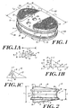
- FIGS. 1, 1A, 1B, 2, 3, 4 and 5 show an implantable prosthetic element 10 which has a first end plate 12 and a second end plate 14.
- the first end plate 12 has a bone-facing surface 42 and an opposed mating surface 44
- the second end plate 14 has a bone-facing surface 46 and an opposed mating surface 48.
- An elastomeric core 16 is interposed between and attached to the mating surfaces 44, 46 of the first and second end plates 12, 14.
- the first and second end plates 12, 14 include bone-facing surfaces 42, 46.
- the bone facing surface 42 of the first end plate 12 includes adjacent lobes 22, 23 separated by at least one slot 20.
- the slot 20 may include one or more extraction recesses 26, formed as blind bores in the slot surface.
- a further surface feature 26A may also be formed on the surface of slot 20 of the bone-facing surface 42 of the first end plate 12, serving as a visual key to indicate the top or superior surface of element 10.
- Surface feature 26A may be in the form of a recess or a protrusion.
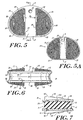
- the second end plate 14 has a bone-facing surface 46 with adjacent lobes 24, 25 that are separated by a slot 21.
- Either or both of the bone-facing surfaces 42, 46 of the first end plate 12 and the second end plate 14 of the element 10 can include one or more bone-penetrating, wedge-like fins 18 protruding therefrom.
- the bone-facing surfaces 42, 46 may include only a single lobe, or more than two lobes. If only a single lobe is present, there need not be a slot. If more than two lobes are present, more than one slot may exist.
- each lobe 22, 23, 24, 25 is elevated above the surfaces of slots 20, 21.
- FIGS. 2 and 7 illustrate that the dimensions and geometry of the end plates 12, 14 and the lobes 22, 23, 24, 25 cause the overall thickness (T) of the element 10 to taper from the anterior face (A) to the posterior face (P) at an angle in the range of about 2° to 35°, and more preferably about 5° to 15°.
- the thickness (T) of the element 10 is greatest when measured between the anterior portions of the lobes, and least when measured between the posterior portions of the lobes.
- the thickness T of element 10 at the anterior side is in the range of about 5 to 21 mm, while the thickness T at the posterior side is in the range of about 1 mm to 15 mm.
- Element 10 has an anterior side (A) and a posterior side (P), with an anterior-posterior (A-P) axis 100 extending therebetween.
- a transverse axis 200 extends through element 10 perpendicular to the A-P axis 100.
- each of the first and second bone-facing surfaces 42, 46 includes a peripheral flange 54, 56 which extends beyond the perimeter of the lobes 22, 23, 24, 25.
- the peripheral flanges 54, 56 of the bone-facing surfaces 42, 46 are similarly sized and shaped.
- element 10 may contain bone-penetrating, wedge-like fins 18 to enhance secure implantation of the element 10 at the desired location, and to prevent the expulsion of the element from its implantation location.
- the fins 18 may vary in shape, number, and in their placement on either of both of the end plates 12, 14.
- exemplary fins 18 are elongated, with a length (L f ) that extends from a leading end 17 of each fin to a trailing end 19 of each fin such that the length of each fin is greater than a width (W f ) of each fin.
- Each fin 18 also has a height (H f ) that increases from the leading end 17 of the fin to the trailing end 19 of each fin.
- the height H f of each fin 18 is in the range of about 0.1 mm to 5.0 mm, and more preferably in the range of about 1.0 mm to 2.0 mm. at the trailing end 19 of the fin.
- each fin is in the range of about 1 mm to 30 mm, and more preferably about 3 mm to 9 mm, and the width W f of each fin, at its widest point, is in the range of about 1 mm to 4 mm.
- each fin Due to the increasing height of each fin from leading end 17 to trailing end 19, the crest 36 of each fin extends from the leading end 17 of the fin to the trailing end 19 of the fin at an angle of extension ( ⁇ ).
- the angle of extension ⁇ may be in the range of about 5° to 85° with respect to a horizontal reference (H).
- each fin 18 may have a substantially triangular profile, with supporting legs 38, 40 that form first and second bone-contacting surfaces 30, 32 that diverge from the crest 36.
- the supporting legs 38, 40 extend from the crest 36 to the bone-facing, superior surface 42, 46 of an end plate 12, 14 at an angle ( ⁇ ) in the range of about 5° ° to 85° ° from a vertical reference (V) as shown in FIG. 1C.
- the trailing end 19 of each fin 18 includes an end face 34 that extends from the crest 36 to the bone-facing surface 42, 46 of end plates 12, 14.
- the end face 34 is generally anterior-facing.
- the end face 34 is shown in FIG. 1B as being substantially perpendicular to a horizontal reference (H) and substantially parallel to a vertical reference (V). End face 34, however, may also be non-parallel to the vertical reference (V), such as, for example, undercut or overcut with respect to the vertical reference (V) as shown by dashed lines in FIG. 1C.
- fins 18 are described and illustrated as having a substantially wedge-like shape with a triangular profile, one of ordinary skill in the art will appreciate that other shapes may be used as well. It is also understood that the dimensions, i.e., height, length, and width of the fins may vary, as may the overall geometry of the fins.
- the number of fins 18 there should generally be at least one fin protruding from each of the bone-facing surface 42 of the first end plate 12 and the bone-facing surface 46 of the second end plate 14.
- the number of fins on each of the bone-facing surface 42 of the first end plate 12 and the bone-facing surface of the second end plate 14 is identical.
- the number of fins protruding from each bone-facing surface 42, 46 is four (see FIGS. 3 and 5) and six (see FIGS. 3A, 3B and 5A).
- the number of fins 18 protruding from each bone-facing surface 42, 46 need not be identical.
- the number of fins 18 protruding from each bone-facing, superior surface 42, 46 may be greater than six or less than four.
- Each fin 18 should be arranged on bone-facing surfaces 42, 46 such that the crests 36 of each fin are substantially parallel to each other.
- the fins 18 are arranged such that crests 36 are substantially parallel to the anterior-posterior axis 100 of the element.
- the fins 18 may be oriented such that crests 36 extend at an angle with respect to the anterior-posterior (A-P) axis 100.
- A-P anterior-posterior
- the fins 18 should be oriented so that the crests 36 are parallel with the desired angle of insertion to be used by a surgeon during surgical installation of element 10.
- the crests 36 of the fins 18 will be parallel to the A-P axis 100 if an anterior surgical approach is to be used.
- the crests 36 of the fins will be angled as shown in FIG. 3B if an anterior-lateral approach is to be used.
- One of ordinary skill in the art can readily determine an appropriate angular orientation of fins 18.
- the fins 18 may be arranged on the bone-facing surfaces 42, 46 in a variety of patterns, which will be readily apparent to one of ordinary skill in the art. Exemplary patterns are illustrated in FIGS. 1, 3, 3A, 3B, 5 and 5A.
- an implantable prosthetic element can be constructed without fins.
- the elastomeric core 16 is interposed between and attached to the first end plate 12 and the second end plate 14 as disclosed in US-5824094.
- the core 16 has a superior core surface 50, an inferior core surface 52 and a central peripheral portion 58.
- peripheral flanges 54, 56 form the perimeter or widest portions of the first and second end plates 12, 14.
- the perimeter of the core peripheral portion 58 is generally about equal to the perimeter of the first and second peripheral flanged portions 54, 56 at the superior and inferior core surfaces 50, 52.
- the core 16 is preferably sub-flush with respect to the end plates 12, 14 such that the perimeter of the core peripheral portion 58 tapers inward to a center portion from both the superior core surface 50 and the inferior core surface 52.
- the perimeter of the central peripheral portion 58 of core 16 is generally less than the perimeter of the superior and inferior core surfaces 50, 52 of core by an amount in the range of about 0.1 mm to 4 mm.
- the peripheral flanges 54, 56 may be different sizes, and the perimeter of the core 16 need not be sub-flush with respect to end plates 12, 14.
- the lobes 22, 23, 24, 25 may have various shapes and dimensions in accordance with the present invention.
- Each lobe has an anterior portion, a posterior portion and first and second side portions.
- lobe 22 has an anterior portion 60, a posterior portion 62, a first side portion 64, and a second side portion 66
- lobe 23 has an anterior portion 70, a posterior portion 72, a first side portion 74, and a second side portion 76.
- lobe 24 has an anterior portion 80, a posterior portion, 82, a first side portion 84, and a second side portion 86
- lobe 23 has an anterior portion 90, a posterior portion 92, a first side portion 94, and a second side portion 96.
- Lobes 22, 23, 24, 25 have heights that are defined as the distance each lobe protrudes from the surface of slots 20, 21 of end plates 12, 14.
- the orientation of the bone-facing surfaces 42, 46 which are generally angled from the anterior side to the posterior side with respect to horizontal, has the effect that the height of each of lobes 22, 23, 24, 25 decreases from their anterior portions 60, 70, 80, 90 to their posterior portions 62, 72, 82, 92.
- the height of each lobe 22, 23, 24, 25 is in the range of about 1 mm to 6 mm at the anterior side to about 0.1 mm to 1.0 mm at the posterior side
- each of lobes 22, 23, 24, 25 is coated, plated or otherwise treated as is generally known in the art to provide a surface with features that promote osteo-integration.
- the osteo-integration enhancing surface features may be provided by, for example, applying a porous or beaded coating of a biocompatible material (e.g., titanium), a mesh layer, or a hydroxy apatite coating.
- a biocompatible material e.g., titanium
- a mesh layer e.g., a mesh layer
- a hydroxy apatite coating e.g., hydroxy apatite coating.
- the slots 20, 21 represent unlobed areas of the bone-facing surfaces 42, 46 of the end plates 12, 14.
- the widths (W1, W2) of slots 20, 21 may be substantially constant along the entire anterior-posterior length (L AP ) of the element 10.
- the widths (W1, W2) should be sufficient to enable an installation tool (not shown) to grasp the element 10, and position the element in its implantation site.
- the widths (W1, W2) of slots 20, 21 generally are equal.
- widths W1 And W2 are shown as being identical and substantially constant and oriented to be parallel to the anterior-posterior axis 100 of the element 10. This design is preferred when the element 10 is to be inserted via an anterior approach.
- the slots 20, 21 may be configured in other ways to accommodate an anterior-lateral insertion technique.
- the width (W1, W2) of slots 20, 21 can increase from the anterior side to the posterior side, or from the posterior side to the anterior side, as shown in FIG. 3B by dashed lines.
- FIG. 5A illustrates another alternative in which the slots 20, 21 (shown by dashed lines) are widest at the anterior side and narrowest at the posterior side of the element 10.
- the width (W1, W2) is generally in the range of about 4 mm to 14 mm.
- FIGS. 8, 8A, 9, and 9A further illustrate the geometry of lobes 22, 23, 24, and 25.
- the bone-facing surfaces 42, 46 of end plates 12, 14 are substantially angled, sloping from the anterior to the posterior sides of the element 10.
- the lobes 22, 23, 24, and 25 each have substantially dome-like profiles, causing them to be curved in both the sagittal and coronal planes.
- FIGS. 4, 6, 8A and 9A illustrate the radius of curvature in the coronal plane of lobes 22, 23, 24, and 25 of end plates 12, 14.
- FIGS. 4 and 6 illustrate that the curve of the lobes 22, 23, 24, and 25 in the coronal plane is truncated by slots 20, 21.
- the radius of curvature of lobes 22 and 23 of end plate 12 (R C1 ) is in the range of about 50 mm to 350 mm, and is preferably in the range of about 100 mm to 200 mm. Most preferably, R C1 is about 150 mm.
- the radius of curvature of lobes 24 and 25 of end plate 14 (R C2 ) is generally flatter than R C1 .
- R C2 may be in the range of about 50 mm to 350 mm, and more preferably is in the range of about 200 mm to 300 mm. Most preferably, R C2 is about 265 mm.
- FIGS. 2, 7, 8 and 9 illustrate the radius of curvature in the sagittal plane of lobes 22, 23, 24, and 25 of end plates 12, 14.
- the lobes have a substantially dome-like profile.
- the radius of curvature of the lobes 22, 23 of end plate 12 (R S1 ) and the radius of curvatures of the lobes 24, 25 of the end plate 14 (R S2 ) are generally equal.
- the value of R S1 and K S2 may be in the range of about 50 mm to 350 mm, and preferably about 100 mm to 200 mm. Most preferably, R S1 and R S2 are about 140 mm.
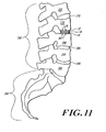
- FIGS. 10 and 11 depict the sacrum 300 and lumbar portion 310 of the spine, and the five lumbar vertebrae 320, 330, 340, 350, 360.
- Natural discs 370, 380, 390 are located between vertebrae 320 and 330, 340 and 350, and 350 and 360.
- the natural disc that was present between vertebrae 330 and 340 has been removed and will be replaced by element 10.
- the element 10 may replace discs 370, 380 or 390, and may also replace discs located between thoracic vertebrae (not shown) or cervical vertebrae (not shown) of the spine.
- the element 10 is implanted with an insertion tool (not shown) between lumbar vertebrae 330, 340 using an anterior approach as indicated by the arrows in FIG. 10. Specifically, the posterior portions 62, 72, 82, 92 of lobes 22, 23, 24, 25 of the end plates 12, 14 are inserted prior to the anterior portions 60, 70, 80, 90 of the lobes.
- the element 10 may be inserted in other directions including, but not limited to, in an anterior-lateral direction.
- the element 10 may be constructed according to the present invention in a variety of sizes depending upon factors such as patient size and intended location in the spine.
- the element 10 has an anterior (A) to posterior (P) length (L AP ) in the range of about 5 mm to 40 mm, and a transverse length (L T ) in the range of about 10 mm to 60 mm.
- Exemplary elements 10 may have dimensions (L AP x L T ) of 34 mm x 46 mm, 31.5 mm x 43 mm, 29 mm x 40 mm, 26.5 mm x 37 mm, and 24 mm x 34 mm.
- the element also has a posterior (P) aspect thickness that may be in the range of about 1 mm to 15 mm, and an anterior (A) aspect thickness that may be in the range of about 5 mm to 21 mm.
- the first end plate 12, second end plate 14, fins 18 and core 16 of the element 10 may be made of a variety of materials well known to those having ordinary skill in the art.
- the first and second end plates 12, 14 and the fins 18 are preferably made of the same material, such as a biocompatible metal or biocompatible metal-based alloy.
- An exemplary metal is titanium
- exemplary alloys include, but are not limited to, stainless steel (e.g., 316 LVM stainless steel), a titanium-vanadium-aluminum alloy (e.g., an alloy having about 90% by weight titanium, about 6% by weight aluminum, and about 4% by weight vanadium), a cobalt-chromium alloy, a cobalt-chromium-molybdenum alloy and a cobalt-nickel-chromium-molybdenum alloy.
- the end plates 12, 14 may also be made of other biocompatible materials including, but not limited to, a composite plastic material.
- the core 16 may be made of any material that simulates the characteristics of a natural disc. Exemplary materials include, but are not limited to, elastomeric materials, a polyolefin rubber (such as a non-conjugated diolefin as described in US-5245098), or a carbon black reinforced polyolefin rubber.
- the hardness of the elastomeric core 16 should be between 56-72 shore A durometer, while the ultimate tensile strength of the core should be greater than 1600 psi.
- the core should have an ultimate elongation greater than 300% using the ASTM D412-87 testing method, and a tear resistance greater than 100 psi using the ASTM D624-86 testing method.
Landscapes
- Health & Medical Sciences (AREA)
- Engineering & Computer Science (AREA)
- Biomedical Technology (AREA)
- Orthopedic Medicine & Surgery (AREA)
- Neurology (AREA)
- Heart & Thoracic Surgery (AREA)
- Oral & Maxillofacial Surgery (AREA)
- Transplantation (AREA)
- Cardiology (AREA)
- Vascular Medicine (AREA)
- Life Sciences & Earth Sciences (AREA)
- Animal Behavior & Ethology (AREA)
- General Health & Medical Sciences (AREA)
- Public Health (AREA)
- Veterinary Medicine (AREA)
- Prostheses (AREA)
- Surgical Instruments (AREA)
- Dental Prosthetics (AREA)
Abstract
Description
- The present invention relates to medical devices, and particularly to prosthetic implant components, and more particularly to an implantable artificial spinal disc.
- Advancing age, as well as injuries, can lead to changes in the various bones, discs, joints, and ligaments of the body. Such changes and injuries often manifest themselves in the form of damage or degeneration of a spinal disc, the result of which is mild to severe chronic back pain. Under certain circumstances, this pain can be lessened or completely alleviated by removal of the damaged or degenerated spinal disc, followed by the implantation of an artificial intervertebral disc.
- Many artificial intervertebral discs are known, such as those disclosed in US-5893889, US-5683465, US-5674294, US-5458643, US-5306309, US-5246458 and US-4759769. There remains a need, however, to substantially simulate a healthy spinal disc, while still allowing for ease of insertion and/or removal of the prosthetic device, and while providing adequate protection against expulsion of the implanted prosthetic disc. Thus, it remains a goal in the art to produce a prosthetic device, such as an artificial intervertebral disc, that possesses these properties.
- The present invention provides an implantable prosthetic element. Although the invention is primarily shown and described as an artificial disc prosthesis, it is understood that the invention has other applications as well, such as for use as an ankle or heel prosthesis.
- The implantable prosthetic element has a first end plate and a second end plate, each of which has a bone-facing surface and an opposed mating surface. The bone-facing surfaces of the first end plate and the second end plate each have a plurality of lobes protruding therefrom. An elastomeric core is interposed between and attached to the mating surfaces of the first end plate and the second end plate. The prosthetic element is constructed such that the thickness is greater at the anterior side than at the posterior side. As a result, the lobe surface is generally oriented at an angle, sloping from the anterior to the posterior side.
- Some or all of the plurality of lobes include one or more wedge-like fins which protrude therefrom. The lobes may also include a plurality of surface features that promote osteo-integration.
- In one embodiment of the present invention, the first end plate and the second end plate each contain two lobes, with a slot separating the two lobes of each end plate. Each slot may optionally include one or more recesses to facilitate insertion and/or extraction of the element from its implantation site.
- The invention will be more fully understood from the following detailed description taken in conjunction with the accompanying drawings, in which:
- FIG. 1 is a perspective view of an implantable prosthetic element in accordance with the present invention;
- FIG. 1A is a top, plan view of a wedge-like fin of the element of FIG. 1;
- FIG. 1B is a perspective view of a wedge-like fin of the element of FIG. 1;
- FIG. 1C is a side view of a wedge-like fin of the element of FIG. 1C;
- FIG. 2 is a side, elevational view of the implantable prosthetic element of FIG. 1;
- FIG. 3 is a plan view of the bone-facing surface of the first end plate of the implantable prosthetic element of FIG. 1;
- FIG. 3A is a plan view of an alternate embodiment of the bone-facing surface of the first end plate of the implantable prosthetic element of FIG. 1;
- FIG. 3B is a plan view of another embodiment of the bone-facing surface of the first end plate of the implantable prosthetic element of FIG. 1;
- FIG. 4 is a front, elevational view of the implantable prosthetic element of FIG. 1;
- FIG. 5 is a plan view of the bone-facing surface of the second end plate of the implantable prosthetic element of FIG. 1;
- FIG. 5A is a plan view of an alternate embodiment of the bone-facing surface of the second end plate of the implantable prosthetic element of FIG. 1;
- FIG. 6 is a front, elevational view of the implantable prosthetic element of FIG. 1;
- FIG. 7 is a sectional view along line 7-7 of the implantable prosthetic element of FIG. 4;
- FIG. 8 is a sectional view along line 8-8 of the implantable prosthetic element of FIG. 3;
- FIG. 8A is a sectional view along line 8A-8A of FIG. 8;
- FIG. 9 is a sectional view along line 9-9 of the implantable prosthetic element of FIG. 5;
- FIG. 9A is a sectional view along line 9A-9A of FIG. 9;
- FIG. 10 is a schematic view of the implantable prosthetic element of FIG. 1 immediately prior to its insertion between spinal vertebrae; and
- FIG. 11 is a schematic view of the implantable prosthetic element of FIG. 1 following its insertion between spinal vertebrae.
-
- Referring to the drawings, FIGS. 1, 1A, 1B, 2, 3, 4 and 5 show an implantable
prosthetic element 10 which has afirst end plate 12 and asecond end plate 14. Thefirst end plate 12 has a bone-facingsurface 42 and anopposed mating surface 44, and thesecond end plate 14 has a bone-facingsurface 46 and anopposed mating surface 48. Anelastomeric core 16 is interposed between and attached to themating surfaces second end plates - The first and
second end plates surfaces bone facing surface 42 of thefirst end plate 12 includesadjacent lobes slot 20. Theslot 20 may include one ormore extraction recesses 26, formed as blind bores in the slot surface. Afurther surface feature 26A may also be formed on the surface ofslot 20 of the bone-facingsurface 42 of thefirst end plate 12, serving as a visual key to indicate the top or superior surface ofelement 10.Surface feature 26A may be in the form of a recess or a protrusion. Similarly, as shown in FIGS. 5 to 7, thesecond end plate 14 has a bone-facingsurface 46 withadjacent lobes slot 21. Either or both of the bone-facingsurfaces first end plate 12 and thesecond end plate 14 of theelement 10 can include one or more bone-penetrating, wedge-like fins 18 protruding therefrom. - The bone-facing
surfaces - In the illustrated embodiment, each
lobe slots end plates lobes element 10 to taper from the anterior face (A) to the posterior face (P) at an angle in the range of about 2° to 35°, and more preferably about 5° to 15°. Thus, the thickness (T) of theelement 10 is greatest when measured between the anterior portions of the lobes, and least when measured between the posterior portions of the lobes. The thickness T ofelement 10 at the anterior side is in the range of about 5 to 21 mm, while the thickness T at the posterior side is in the range of about 1 mm to 15 mm. -
Element 10 has an anterior side (A) and a posterior side (P), with an anterior-posterior (A-P)axis 100 extending therebetween. Atransverse axis 200 extends throughelement 10 perpendicular to theA-P axis 100. As shown in FIGS. 1, 2, 4, 6 and 7, each of the first and second bone-facingsurfaces peripheral flange lobes peripheral flanges surfaces - As noted above,
element 10 may contain bone-penetrating, wedge-like fins 18 to enhance secure implantation of theelement 10 at the desired location, and to prevent the expulsion of the element from its implantation location. Thefins 18 may vary in shape, number, and in their placement on either of both of theend plates - As illustrated,
exemplary fins 18 are elongated, with a length (Lf) that extends from a leadingend 17 of each fin to a trailingend 19 of each fin such that the length of each fin is greater than a width (Wf) of each fin. Eachfin 18 also has a height (Hf) that increases from the leadingend 17 of the fin to the trailingend 19 of each fin. In one embodiment, the height Hf of eachfin 18 is in the range of about 0.1 mm to 5.0 mm, and more preferably in the range of about 1.0 mm to 2.0 mm. at the trailingend 19 of the fin. Generally, the length Lf of each fin is in the range of about 1 mm to 30 mm, and more preferably about 3 mm to 9 mm, and the width Wf of each fin, at its widest point, is in the range of about 1 mm to 4 mm. - Due to the increasing height of each fin from leading
end 17 to trailingend 19, thecrest 36 of each fin extends from the leadingend 17 of the fin to the trailingend 19 of the fin at an angle of extension (α). The angle of extension α may be in the range of about 5° to 85° with respect to a horizontal reference (H). - As shown in FIGS. 1 and 1A to 1C, each
fin 18 may have a substantially triangular profile, with supportinglegs surfaces crest 36. The supportinglegs crest 36 to the bone-facing,superior surface end plate - In one embodiment, the trailing
end 19 of eachfin 18 includes anend face 34 that extends from thecrest 36 to the bone-facingsurface end plates end face 34 is generally anterior-facing. Theend face 34 is shown in FIG. 1B as being substantially perpendicular to a horizontal reference (H) and substantially parallel to a vertical reference (V).End face 34, however, may also be non-parallel to the vertical reference (V), such as, for example, undercut or overcut with respect to the vertical reference (V) as shown by dashed lines in FIG. 1C. - Although
fins 18 are described and illustrated as having a substantially wedge-like shape with a triangular profile, one of ordinary skill in the art will appreciate that other shapes may be used as well. It is also understood that the dimensions, i.e., height, length, and width of the fins may vary, as may the overall geometry of the fins. - With respect to the number of
fins 18, there should generally be at least one fin protruding from each of the bone-facingsurface 42 of thefirst end plate 12 and the bone-facingsurface 46 of thesecond end plate 14. Preferably, the number of fins on each of the bone-facingsurface 42 of thefirst end plate 12 and the bone-facing surface of thesecond end plate 14 is identical. In exemplary embodiments of the present invention, the number of fins protruding from each bone-facingsurface fins 18 protruding from each bone-facingsurface fins 18 protruding from each bone-facing,superior surface - Each
fin 18 should be arranged on bone-facingsurfaces crests 36 of each fin are substantially parallel to each other. In one embodiment, shown in FIGS. 3, 3A, 5 and 5A, thefins 18 are arranged such that crests 36 are substantially parallel to the anterior-posterior axis 100 of the element. In other embodiments, for example FIG. 3B, thefins 18 may be oriented such that crests 36 extend at an angle with respect to the anterior-posterior (A-P)axis 100. One of ordinary skill in the art will readily appreciate that thefins 18 should be oriented so that thecrests 36 are parallel with the desired angle of insertion to be used by a surgeon during surgical installation ofelement 10. For example, ifelement 10 is to be used as an artificial intervertebral disc, thecrests 36 of thefins 18 will be parallel to theA-P axis 100 if an anterior surgical approach is to be used. Alternatively, thecrests 36 of the fins will be angled as shown in FIG. 3B if an anterior-lateral approach is to be used. One of ordinary skill in the art can readily determine an appropriate angular orientation offins 18. - The
fins 18 may be arranged on the bone-facingsurfaces - Although
fins 18 are included in the illustrated embodiment of the invention, an implantable prosthetic element can be constructed without fins. - As shown in FIGS. 1, 2, 4, 6 and 7, the
elastomeric core 16 is interposed between and attached to thefirst end plate 12 and thesecond end plate 14 as disclosed in US-5824094. Thecore 16 has asuperior core surface 50, aninferior core surface 52 and a centralperipheral portion 58. - As noted above,
peripheral flanges second end plates peripheral portion 58 is generally about equal to the perimeter of the first and second peripheralflanged portions core 16 is preferably sub-flush with respect to theend plates peripheral portion 58 tapers inward to a center portion from both thesuperior core surface 50 and theinferior core surface 52. Thus, the perimeter of the centralperipheral portion 58 ofcore 16 is generally less than the perimeter of the superior and inferior core surfaces 50, 52 of core by an amount in the range of about 0.1 mm to 4 mm. One of ordinary skill in the art will understand, however, that alternate geometries may be utilized as well. For example, theperipheral flanges end plates - The
lobes lobe 22 has ananterior portion 60, aposterior portion 62, afirst side portion 64, and a second side portion 66, whilelobe 23 has ananterior portion 70, a posterior portion 72, afirst side portion 74, and a second side portion 76. As shown in FIG. 5,lobe 24 has ananterior portion 80, a posterior portion, 82, afirst side portion 84, and asecond side portion 86, whilelobe 23 has ananterior portion 90, aposterior portion 92, afirst side portion 94, and asecond side portion 96. -
Lobes slots end plates surfaces lobes anterior portions posterior portions lobe - In an exemplary embodiment of the present invention, each of
lobes lobes surfaces - As noted above, the
slots surfaces end plates slots element 10. The widths (W1, W2) should be sufficient to enable an installation tool (not shown) to grasp theelement 10, and position the element in its implantation site. The widths (W1, W2) ofslots - In FIGS. 1, 3, 5 and 5A widths W1 And W2 are shown as being identical and substantially constant and oriented to be parallel to the anterior-
posterior axis 100 of theelement 10. This design is preferred when theelement 10 is to be inserted via an anterior approach. Alternatively, theslots slots slots 20, 21 (shown by dashed lines) are widest at the anterior side and narrowest at the posterior side of theelement 10. In either embodiment, the width (W1, W2) is generally in the range of about 4 mm to 14 mm. - FIGS. 8, 8A, 9, and 9A further illustrate the geometry of
lobes surfaces end plates element 10. In addition to being mounted upon this canted surface of theend plates lobes - FIGS. 4, 6, 8A and 9A illustrate the radius of curvature in the coronal plane of
lobes end plates lobes slots lobes lobes - FIGS. 2, 7, 8 and 9 illustrate the radius of curvature in the sagittal plane of
lobes end plates lobes lobes - Referring now to FIGS. 10 and 11, the
element 10 of the present invention is shown immediately prior to (see FIG. 10) and following (see FIG. 11) its implantation. Specifically, FIGS. 10 and 11 depict thesacrum 300 andlumbar portion 310 of the spine, and the fivelumbar vertebrae Natural discs vertebrae vertebrae element 10. One of ordinary skill in the art will recognize that theelement 10 may replacediscs - The
element 10 is implanted with an insertion tool (not shown) betweenlumbar vertebrae posterior portions lobes end plates anterior portions element 10 may be inserted in other directions including, but not limited to, in an anterior-lateral direction. Once implanted (see FIG. 11), the first and second bone-contactingsurfaces fin 18 of thefirst end plate 12 penetratevertebra 330, while the first and second bone-contactingsurfaces second end plate 14 penetratevertebra 340. - The
element 10 may be constructed according to the present invention in a variety of sizes depending upon factors such as patient size and intended location in the spine. Generally, theelement 10 has an anterior (A) to posterior (P) length (LAP) in the range of about 5 mm to 40 mm, and a transverse length (LT) in the range of about 10 mm to 60 mm.Exemplary elements 10 may have dimensions (LAP x LT) of 34 mm x 46 mm, 31.5 mm x 43 mm, 29 mm x 40 mm, 26.5 mm x 37 mm, and 24 mm x 34 mm. The element also has a posterior (P) aspect thickness that may be in the range of about 1 mm to 15 mm, and an anterior (A) aspect thickness that may be in the range of about 5 mm to 21 mm. - The
first end plate 12,second end plate 14,fins 18 andcore 16 of theelement 10 may be made of a variety of materials well known to those having ordinary skill in the art. The first andsecond end plates fins 18 are preferably made of the same material, such as a biocompatible metal or biocompatible metal-based alloy. An exemplary metal is titanium, while exemplary alloys include, but are not limited to, stainless steel (e.g., 316 LVM stainless steel), a titanium-vanadium-aluminum alloy (e.g., an alloy having about 90% by weight titanium, about 6% by weight aluminum, and about 4% by weight vanadium), a cobalt-chromium alloy, a cobalt-chromium-molybdenum alloy and a cobalt-nickel-chromium-molybdenum alloy. Theend plates - The core 16 may be made of any material that simulates the characteristics of a natural disc. Exemplary materials include, but are not limited to, elastomeric materials, a polyolefin rubber (such as a non-conjugated diolefin as described in US-5245098), or a carbon black reinforced polyolefin rubber. The hardness of the
elastomeric core 16 should be between 56-72 shore A durometer, while the ultimate tensile strength of the core should be greater than 1600 psi. The core should have an ultimate elongation greater than 300% using the ASTM D412-87 testing method, and a tear resistance greater than 100 psi using the ASTM D624-86 testing method.
Claims (41)
- An implantable prosthetic element, comprising:a first end plate having a first bone-facing surface and an opposed mating surface, the first bone-facing surface having at least one lobe protruding therefrom;a second end plate having a second bone-facing surface and an opposed mating surface, the second bone-facing surface having at least one lobe protruding therefrom; anda core interposed between and attached to the mating surfaces of the first end plate and the second end plate,in which the bone-facing surface of at least one of the first end plate and the second end plate includes at least one bone-penetrating fin protruding therefrom.
- An element as claimed in claim 1, in which each of the at least one bone-penetrating fins is elongated, having a length greater than a width, in which the length extends from a leading end of each fin to a trailing end of each fin, and in which each fin has a height that increases from the leading end to the trailing end.
- An element as claimed in claim 2, in which the leading end of each of the at least one fins is substantially flush with the bone-facing surface of the end plate, and the trailing end of each of the at least one fins is raised from the bone facing surface by a height in the range of about 0.1 mm to 5.0 mm.
- An element as claimed in claim 2, in which the length of each of the at least one fins is in the range of about 1 mm to 30 mm.
- An element as claimed in claim 2, in which each of the at least one fins has a crest extending from the leading end to the trailing end at an angle with respect to horizontal in the range of about 5° to 85°.
- An element as claimed in claim 2, in which each of the at least one fins has a substantially triangular profile forming first and second bone-contacting surfaces, with supporting legs diverging away from the crest at opposite sides thereof.
- An element as claimed in claim 6, in which the trailing end of each of the at least one fins includes an end face that extends from the crest to the bone-facing surface of the end plate.
- An element as claimed in claim 7, in which the end face is oriented at about 90° with respect to horizontal.
- An element as claimed in claim 1, in which a plurality of fins are provided on each of the first end plate and the second end plate.
- An element as claimed in claim 1, in which at least one fin protrudes from each lobe of the first and second end plates.
- An element as claimed in claim 9, in which the number of fins that protrude from the first end plate is equal to the number of fins that protrude from the second end plate.
- An element as claimed in claim 1, in which at least two fins protrude from each of the first and second end plates.
- An element as claimed in claim 1, in which the bone facing surface of the first end plate has a first lobe and a second lobe and the bone facing surface of the second end plate has a third lobe and a fourth lobe, and in which a first slot is defined between the first lobe and the second lobe, and a second slot is defined between the third lobe and the fourth lobe.
- An element as claimed in claim 13, in which the first and second slots each have a constant width from an anterior end of the element to a posterior end of the element.
- An element as claimed in claim 13, in which the first and second slots each have a width that decreases from an anterior side of the element to a posterior side of the element.
- An element as claimed in claim 13, in which the first and second slots each have a width that increases from an anterior side of the element to a posterior side of the element.
- An element as claimed in claim 14, in which each of the first and second slots contain at least one extraction recess.
- An element as claimed in claim 13, in which each of the at least one first and second lobes has a height, an anterior portion, a posterior portion, and first and second side portions, and in which the height of each lobe decreases from the anterior portion to the posterior portion and increases from the first side portion to the second side portion.
- An element as claimed in claim 5, in which the crest is oriented so as to be parallel to an anterior-posterior axis of the element.
- An element as claimed in claim 5, in which the crest is oriented at an angle with respect to an anterior-posterior axis of the element.
- An element as claimed in claim 1, in which each of the at least one of the lobes formed on the first end plate and the second end plate include osteo-integration enhancing surface features.
- An element as claimed in claim 21, in which the osteo-integration enhancing surface features are selected from the group consisting of a porous coating, a beaded coating, a mesh layer and a hydroxy apatite coating.
- An element as claimed in claim 1, in which the element has a posterior aspect thickness in the range of about 1 millimeter to 15 millimeters.
- An element as claimed in claim 1, in which the element has an anterior-posterior length in the range of about 5 millimeters to 40 millimeters.
- An element as claimed in claim 1, in which the element has a transverse length in the range of about 10 millimeters to 60 millimeters.
- An element as claimed in claim 1, in which the first end plate and the second end plate each have a sagittal radius in the range of 50 millimeters to 350 millimeters and a coronal radius in the range of 50 millimeters to 350 millimeters.
- An element as claimed in claim 7, in which the end face is undercut with respect to vertical.
- An element as claimed in claim 7, in which the end face is overcut with respect to vertical.
- An element as claimed in claim 1, in which the core is formed of an elastomeric material.
- An element as claimed in claim 1, in which the core is formed of a material selected from the group consisting of an elastomeric material and a polyolefin rubber.
- An element as claimed in claim 30, in which the polyolefin rubber is carbon black reinforced.
- An implantable prosthetic element, comprising:a first end plate having a first bone-facing surface and an opposed first mating surface, the first bone-facing surface having at least lobe protruding therefrom;a second end plate having a second bone-facing surface and an opposed second mating surface, the second bone-facing surface having at least one lobe protruding therefrom; andan elastomeric core interposed between and attached to the inferior mating surfaces of the first end plate and the second end plate.
- An element as claimed in claim 32, in which the first bone facing surface of the first end plate has two adjacent lobes protruding therefrom.
- An element as claimed in claim 32, in which the second bone facing surface of the second end plate has two adjacent lobes protruding therefrom.
- An element as claimed in claim 33, in which a slot separates the two lobes.
- An element as claimed in claim 34, in which a slot separates the two lobes.
- An element as claimed in claim 32, which includes at least one bone-penetrating fin formed on the bone-facing surfaces of the first and second end plates.
- An element as claimed in claim 33, in which each of the at least one bone-penetrating fin has a height that increases from a leading end of the fin to a trailing end of the fin.
- An element as claimed in claim 32, in which the core is formed of an elastomeric material.
- An element as claimed in claim 32, in which the core is formed of a material selected from the group consisting of an elastomeric material and a polyolefin rubber.
- An element as claimed in claim 40, in which the polyolefin rubber is reinforced with carbon black.
Applications Claiming Priority (2)
| Application Number | Priority Date | Filing Date | Title |
|---|---|---|---|
| US16727299P | 1999-11-24 | 1999-11-24 | |
| US167272P | 1999-11-24 |
Publications (3)
| Publication Number | Publication Date |
|---|---|
| EP1103237A2 true EP1103237A2 (en) | 2001-05-30 |
| EP1103237A3 EP1103237A3 (en) | 2002-04-24 |
| EP1103237B1 EP1103237B1 (en) | 2006-10-04 |
Family
ID=22606671
Family Applications (1)
| Application Number | Title | Priority Date | Filing Date |
|---|---|---|---|
| EP00310412A Expired - Lifetime EP1103237B1 (en) | 1999-11-24 | 2000-11-23 | Prosthetic implant element |
Country Status (8)
| Country | Link |
|---|---|
| US (1) | US6592624B1 (en) |
| EP (1) | EP1103237B1 (en) |
| JP (1) | JP2001187074A (en) |
| KR (1) | KR20010051919A (en) |
| AT (1) | ATE341294T1 (en) |
| AU (1) | AU772817B2 (en) |
| CA (1) | CA2326919C (en) |
| DE (1) | DE60031073T2 (en) |
Cited By (21)
| Publication number | Priority date | Publication date | Assignee | Title |
|---|---|---|---|---|
| WO2004039291A1 (en) | 2002-10-29 | 2004-05-13 | Spinecore, Inc. | Instrumentation, methods, and features for use in implanting an artificial intervertebral disc |
| WO2004089259A1 (en) * | 2003-04-07 | 2004-10-21 | Cervitech, Inc. | Prosthetic joint of cervical intervertebral discs |
| EP1475059A3 (en) * | 2003-05-06 | 2005-01-12 | Spinal Innovations, Inc. | Artificial intervertebral disc |
| EP1401360A4 (en) * | 2001-07-03 | 2005-05-25 | Axiomed Spine Corp | Artificial disc |
| WO2005107656A1 (en) * | 2004-05-05 | 2005-11-17 | Sdgi Holdings, Inc. | Artificial intervertebral disc for lateral insertion |
| US7169181B2 (en) * | 2002-12-10 | 2007-01-30 | Axiomed Spine Corporation | Artificial disc |
| US7291173B2 (en) | 2003-05-06 | 2007-11-06 | Aesculap Ii, Inc. | Artificial intervertebral disc |
| US7585325B2 (en) | 2004-06-16 | 2009-09-08 | Aesculap Ag | Intervertebral implant |
| US8012212B2 (en) | 2003-04-07 | 2011-09-06 | Nuvasive, Inc. | Cervical intervertebral disk prosthesis |
| US8029569B2 (en) | 2006-11-20 | 2011-10-04 | International Spinal Innovations, Llc | Implantable spinal disk |
| WO2012012327A1 (en) * | 2010-07-20 | 2012-01-26 | X-Spine Systems, Inc. | Composite orthopedic implant having a low friction material substrate with primary frictional features and secondary frictional features |
| US8721725B2 (en) | 2005-06-22 | 2014-05-13 | Cervitech, Inc. | Intervertebral prosthesis with self-tapping fixing projections |
| US8809418B2 (en) | 2004-03-21 | 2014-08-19 | DePuy Synthes Products, LLC | Methods, materials and apparatus for treating bone and other tissue |
| US8956368B2 (en) | 2003-06-17 | 2015-02-17 | DePuy Synthes Products, LLC | Methods, materials and apparatus for treating bone and other tissue |
| US8992541B2 (en) | 2003-03-14 | 2015-03-31 | DePuy Synthes Products, LLC | Hydraulic device for the injection of bone cement in percutaneous vertebroplasty |
| US9642932B2 (en) | 2006-09-14 | 2017-05-09 | DePuy Synthes Products, Inc. | Bone cement and methods of use thereof |
| US9839460B2 (en) | 2003-03-31 | 2017-12-12 | DePuy Synthes Products, Inc. | Remotely-activated vertebroplasty injection device |
| US9918767B2 (en) | 2005-08-01 | 2018-03-20 | DePuy Synthes Products, Inc. | Temperature control system |
| US9987052B2 (en) | 2015-02-24 | 2018-06-05 | X-Spine Systems, Inc. | Modular interspinous fixation system with threaded component |
| US10494158B2 (en) | 2006-10-19 | 2019-12-03 | DePuy Synthes Products, Inc. | Fluid delivery system |
| US10631906B2 (en) | 2005-11-22 | 2020-04-28 | DePuy Synthes Products, Inc. | Apparatus for transferring a viscous material |
Families Citing this family (234)
| Publication number | Priority date | Publication date | Assignee | Title |
|---|---|---|---|---|
| US7799077B2 (en) | 2002-10-07 | 2010-09-21 | Conformis, Inc. | Minimally invasive joint implant with 3-dimensional geometry matching the articular surfaces |
| US9603711B2 (en) | 2001-05-25 | 2017-03-28 | Conformis, Inc. | Patient-adapted and improved articular implants, designs and related guide tools |
| US8735773B2 (en) | 2007-02-14 | 2014-05-27 | Conformis, Inc. | Implant device and method for manufacture |
| US8545569B2 (en) | 2001-05-25 | 2013-10-01 | Conformis, Inc. | Patient selectable knee arthroplasty devices |
| US8617242B2 (en) | 2001-05-25 | 2013-12-31 | Conformis, Inc. | Implant device and method for manufacture |
| US8556983B2 (en) | 2001-05-25 | 2013-10-15 | Conformis, Inc. | Patient-adapted and improved orthopedic implants, designs and related tools |
| US8882847B2 (en) | 2001-05-25 | 2014-11-11 | Conformis, Inc. | Patient selectable knee joint arthroplasty devices |
| US8771365B2 (en) | 2009-02-25 | 2014-07-08 | Conformis, Inc. | Patient-adapted and improved orthopedic implants, designs, and related tools |
| US8480754B2 (en) | 2001-05-25 | 2013-07-09 | Conformis, Inc. | Patient-adapted and improved articular implants, designs and related guide tools |
| FR2897259B1 (en) | 2006-02-15 | 2008-05-09 | Ldr Medical Soc Par Actions Si | INTERSOMATIC TRANSFORAMINAL CAGE WITH INTERBREBAL FUSION GRAFT AND CAGE IMPLANTATION INSTRUMENT |
| US6827740B1 (en) * | 1999-12-08 | 2004-12-07 | Gary K. Michelson | Spinal implant surface configuration |
| US7115143B1 (en) * | 1999-12-08 | 2006-10-03 | Sdgi Holdings, Inc. | Orthopedic implant surface configuration |
| FR2808995B1 (en) | 2000-05-18 | 2003-02-21 | Aesculap Sa | INTERSOMATIC CAGE WITH UNIFIED GRAFT |
| WO2002030337A2 (en) * | 2000-10-11 | 2002-04-18 | Mason Michael D | Graftless spinal fusion device |
| US7169182B2 (en) * | 2001-07-16 | 2007-01-30 | Spinecore, Inc. | Implanting an artificial intervertebral disc |
| US6673113B2 (en) * | 2001-10-18 | 2004-01-06 | Spinecore, Inc. | Intervertebral spacer device having arch shaped spring elements |
| US6669730B2 (en) | 2001-02-15 | 2003-12-30 | Spinecore, Inc. | Intervertebral spacer device utilizing a spirally slotted belleville washer having radially extending grooves |
| US7235081B2 (en) * | 2001-07-16 | 2007-06-26 | Spinecore, Inc. | Wedge plate inserter/impactor and related methods for use in implanting an artificial intervertebral disc |
| US6989032B2 (en) | 2001-07-16 | 2006-01-24 | Spinecore, Inc. | Artificial intervertebral disc |
| FR2824261B1 (en) | 2001-05-04 | 2004-05-28 | Ldr Medical | INTERVERTEBRAL DISC PROSTHESIS AND IMPLEMENTATION METHOD AND TOOLS |
| JP2005504563A (en) | 2001-05-25 | 2005-02-17 | イメージング セラピューティクス,インコーポレーテッド | Methods and compositions for resurfacing joints |
| US20070156171A1 (en) * | 2001-05-25 | 2007-07-05 | Conformis, Inc. | Implant Grasper |
| FR2827156B1 (en) * | 2001-07-13 | 2003-11-14 | Ldr Medical | VERTEBRAL CAGE DEVICE WITH MODULAR FASTENING |
| US6471725B1 (en) * | 2001-07-16 | 2002-10-29 | Third Millenium Engineering, Llc | Porous intervertebral distraction spacers |
| US7160327B2 (en) | 2001-07-16 | 2007-01-09 | Spinecore, Inc. | Axially compressible artificial intervertebral disc having limited rotation using a captured ball and socket joint with a solid ball and compression locking post |
| ATE426377T1 (en) * | 2001-07-16 | 2009-04-15 | Spinecore Inc | ARTIFICIAL DISC WITH A FORCE-RESTORING ELEMENT IN THE FORM OF A WAVE WASHER |
| US6468310B1 (en) * | 2001-07-16 | 2002-10-22 | Third Millennium Engineering, Llc | Intervertebral spacer device having a wave washer force restoring element |
| US7118599B2 (en) | 2001-07-16 | 2006-10-10 | Spinecore, Inc. | Artificial intervertebral disc |
| US7771477B2 (en) | 2001-10-01 | 2010-08-10 | Spinecore, Inc. | Intervertebral spacer device utilizing a belleville washer having radially spaced concentric grooves |
| US7713302B2 (en) | 2001-10-01 | 2010-05-11 | Spinecore, Inc. | Intervertebral spacer device utilizing a spirally slotted belleville washer having radially spaced concentric grooves |
| JP4394441B2 (en) * | 2001-10-02 | 2010-01-06 | レックス メディカル リミテッド パートナーシップ | Spinal implant |
| US6740118B2 (en) * | 2002-01-09 | 2004-05-25 | Sdgi Holdings, Inc. | Intervertebral prosthetic joint |
| AR038680A1 (en) | 2002-02-19 | 2005-01-26 | Synthes Ag | INTERVERTEBRAL IMPLANT |
| US20080027548A9 (en) | 2002-04-12 | 2008-01-31 | Ferree Bret A | Spacerless artificial disc replacements |
| US8038713B2 (en) | 2002-04-23 | 2011-10-18 | Spinecore, Inc. | Two-component artificial disc replacements |
| US7001433B2 (en) * | 2002-05-23 | 2006-02-21 | Pioneer Laboratories, Inc. | Artificial intervertebral disc device |
| US8388684B2 (en) * | 2002-05-23 | 2013-03-05 | Pioneer Signal Technology, Inc. | Artificial disc device |
| US6793678B2 (en) | 2002-06-27 | 2004-09-21 | Depuy Acromed, Inc. | Prosthetic intervertebral motion disc having dampening |
| JP4256345B2 (en) | 2002-08-15 | 2009-04-22 | コップス,ジャスティン,ケー. | Intervertebral disc implant |
| WO2004016217A2 (en) | 2002-08-15 | 2004-02-26 | David Gerber | Controlled artificial intervertebral disc implant |
| ATE455518T1 (en) | 2002-09-19 | 2010-02-15 | Villiers Malan De | INTERVERTEBRAL PROSTHESIS |
| GB0223327D0 (en) * | 2002-10-08 | 2002-11-13 | Ranier Ltd | Artificial spinal disc |
| DE10247762A1 (en) * | 2002-10-14 | 2004-04-22 | Waldemar Link (Gmbh & Co.) | Intervertebral prosthesis |
| FR2846550B1 (en) | 2002-11-05 | 2006-01-13 | Ldr Medical | INTERVERTEBRAL DISC PROSTHESIS |
| WO2004043305A1 (en) | 2002-11-07 | 2004-05-27 | Conformis, Inc. | Methods for determing meniscal size and shape and for devising treatment |
| US20040210310A1 (en) * | 2002-12-10 | 2004-10-21 | Trieu Hai H. | Implant system and method for intervertebral disc augmentation |
| ZA200506026B (en) | 2003-01-31 | 2006-11-29 | Spinalmotion Inc | Intervertebral prosthesis placement instrument |
| EP2329778A3 (en) * | 2003-01-31 | 2012-06-20 | Spinalmotion, Inc. | Spinal midline indicator |
| ATE496593T1 (en) | 2003-02-06 | 2011-02-15 | Synthes Gmbh | INTERVERBARY IMPLANT |
| US20040230309A1 (en) | 2003-02-14 | 2004-11-18 | Depuy Spine, Inc. | In-situ formed intervertebral fusion device and method |
| US6908484B2 (en) | 2003-03-06 | 2005-06-21 | Spinecore, Inc. | Cervical disc replacement |
| US7819903B2 (en) | 2003-03-31 | 2010-10-26 | Depuy Spine, Inc. | Spinal fixation plate |
| EP1610740A4 (en) | 2003-04-04 | 2009-04-08 | Theken Disc Llc | Artificial disc prosthesis |
| US10052211B2 (en) | 2003-05-27 | 2018-08-21 | Simplify Medical Pty Ltd. | Prosthetic disc for intervertebral insertion |
| US7575599B2 (en) | 2004-07-30 | 2009-08-18 | Spinalmotion, Inc. | Intervertebral prosthetic disc with metallic core |
| WO2004105638A2 (en) | 2003-05-27 | 2004-12-09 | Spinalmotion, Inc. | Prosthetic disc for intervertebral insertion |
| US7537612B2 (en) * | 2003-06-20 | 2009-05-26 | Warsaw Orthopedic, Inc. | Lumbar composite nucleus |
| US7008452B2 (en) * | 2003-06-26 | 2006-03-07 | Depuy Acromed, Inc. | Dual durometer elastomer artificial disc |
| US20040267367A1 (en) * | 2003-06-30 | 2004-12-30 | Depuy Acromed, Inc | Intervertebral implant with conformable endplate |
| US20050015150A1 (en) * | 2003-07-17 | 2005-01-20 | Lee Casey K. | Intervertebral disk and nucleus prosthesis |
| US7753958B2 (en) | 2003-08-05 | 2010-07-13 | Gordon Charles R | Expandable intervertebral implant |
| US20050055099A1 (en) * | 2003-09-09 | 2005-03-10 | Ku David N. | Flexible spinal disc |
| US7766914B2 (en) * | 2003-09-10 | 2010-08-03 | Warsaw Orthopedic, Inc. | Adjustable drill guide |
| US7794465B2 (en) * | 2003-09-10 | 2010-09-14 | Warsaw Orthopedic, Inc. | Artificial spinal discs and associated implantation instruments and methods |
| WO2005030034A2 (en) | 2003-09-26 | 2005-04-07 | Depuy Spine, Inc. | Device for delivering viscous material |
| US7655012B2 (en) * | 2003-10-02 | 2010-02-02 | Zimmer Spine, Inc. | Methods and apparatuses for minimally invasive replacement of intervertebral discs |
| US7837732B2 (en) | 2003-11-20 | 2010-11-23 | Warsaw Orthopedic, Inc. | Intervertebral body fusion cage with keels and implantation methods |
| US20050187631A1 (en) * | 2004-01-27 | 2005-08-25 | Sdgi Holdings, Inc. | Prosthetic device |
| US20050165486A1 (en) * | 2004-01-27 | 2005-07-28 | Sdgi Holdings, Inc. | Prosthetic device and method |
| US7250060B2 (en) * | 2004-01-27 | 2007-07-31 | Sdgi Holdings, Inc. | Hybrid intervertebral disc system |
| FR2865629B1 (en) | 2004-02-04 | 2007-01-26 | Ldr Medical | INTERVERTEBRAL DISC PROSTHESIS |
| KR101146215B1 (en) | 2004-02-04 | 2012-05-11 | 엘디알 메디칼 | Intervertebral disc prosthesis |
| JP4510836B2 (en) * | 2004-02-20 | 2010-07-28 | スパインコア,インコーポレイテッド | Artificial intervertebral disc with universal joint |
| US7393361B2 (en) * | 2004-02-20 | 2008-07-01 | Spinecore, Inc. | Artificial intervertebral disc having a bored semispherical bearing with a compression locking post and retaining caps |
| US8636802B2 (en) | 2004-03-06 | 2014-01-28 | DePuy Synthes Products, LLC | Dynamized interspinal implant |
| FR2869528B1 (en) | 2004-04-28 | 2007-02-02 | Ldr Medical | INTERVERTEBRAL DISC PROSTHESIS |
| US8172904B2 (en) * | 2004-06-30 | 2012-05-08 | Synergy Disc Replacement, Inc. | Artificial spinal disc |
| US8454699B2 (en) | 2004-06-30 | 2013-06-04 | Synergy Disc Replacement, Inc | Systems and methods for vertebral disc replacement |
| US9237958B2 (en) * | 2004-06-30 | 2016-01-19 | Synergy Disc Replacement Inc. | Joint prostheses |
| EP1773256B1 (en) * | 2004-06-30 | 2019-11-27 | Synergy Disc Replacement Inc. | Artificial spinal disc |
| US7585326B2 (en) | 2004-08-06 | 2009-09-08 | Spinalmotion, Inc. | Methods and apparatus for intervertebral disc prosthesis insertion |
| US7575600B2 (en) | 2004-09-29 | 2009-08-18 | Kyphon Sarl | Artificial vertebral disk replacement implant with translating articulation contact surface and method |
| US8172855B2 (en) | 2004-11-24 | 2012-05-08 | Abdou M S | Devices and methods for inter-vertebral orthopedic device placement |
| FR2879436B1 (en) | 2004-12-22 | 2007-03-09 | Ldr Medical | INTERVERTEBRAL DISC PROSTHESIS |
| EP1841387B1 (en) * | 2005-01-19 | 2011-12-21 | Nexgen Spine, Inc. | Elastomeric intervertebral disc prosthesis |
| US8864831B2 (en) * | 2005-01-19 | 2014-10-21 | K2M, Inc. | Fixation of elastomer to rigid structures |
| US8083797B2 (en) | 2005-02-04 | 2011-12-27 | Spinalmotion, Inc. | Intervertebral prosthetic disc with shock absorption |
| US7690381B2 (en) * | 2005-02-10 | 2010-04-06 | Depuy Spine, Inc. | Intervertebral prosthetic disc and method for installing using a guidewire |
| US20060229723A1 (en) * | 2005-04-08 | 2006-10-12 | Sdgi Holdings, Inc. | Intervertebral fusion device and method |
| US20060235530A1 (en) * | 2005-04-18 | 2006-10-19 | Shelokov Alexis P | Artificial prosthesis |
| US11096796B2 (en) | 2005-05-06 | 2021-08-24 | Titan Spine, Llc | Interbody spinal implant having a roughened surface topography on one or more internal surfaces |
| US8591590B2 (en) | 2005-05-06 | 2013-11-26 | Titan Spine, Llc | Spinal implant having a transverse aperture |
| US8435302B2 (en) | 2005-05-06 | 2013-05-07 | Titan Spine, Llc | Instruments and interbody spinal implants enhancing disc space distraction |
| US20120312779A1 (en) | 2005-05-06 | 2012-12-13 | Titian Spine, LLC | Methods for manufacturing implants having integration surfaces |
| US8585766B2 (en) | 2005-05-06 | 2013-11-19 | Titan Spine, Llc | Endplate-preserving spinal implant with an integration plate having durable connectors |
| US8480749B2 (en) | 2005-05-06 | 2013-07-09 | Titan Spine, Llc | Friction fit and vertebral endplate-preserving spinal implant |
| US9125756B2 (en) | 2005-05-06 | 2015-09-08 | Titan Spine, Llc | Processes for producing regular repeating patterns on surfaces of interbody devices |
| US8403991B2 (en) | 2005-05-06 | 2013-03-26 | Titan Spine Llc | Implant with critical ratio of load bearing surface area to central opening area |
| US8562684B2 (en) | 2005-05-06 | 2013-10-22 | Titan Spine, Llc | Endplate-preserving spinal implant with an integration plate having a roughened surface topography |
| US8758442B2 (en) | 2005-05-06 | 2014-06-24 | Titan Spine, Llc | Composite implants having integration surfaces composed of a regular repeating pattern |
| US8814939B2 (en) | 2005-05-06 | 2014-08-26 | Titan Spine, Llc | Implants having three distinct surfaces |
| US9168147B2 (en) | 2005-05-06 | 2015-10-27 | Titan Spine, Llc | Self-deploying locking screw retention device |
| US8992622B2 (en) | 2005-05-06 | 2015-03-31 | Titan Spine, Llc | Interbody spinal implant having a roughened surface topography |
| US8617248B2 (en) | 2005-05-06 | 2013-12-31 | Titan Spine, Llc | Spinal implant having variable ratios of the integration surface area to the axial passage area |
| US8585767B2 (en) | 2005-05-06 | 2013-11-19 | Titan Spine, Llc | Endplate-preserving spinal implant with an integration plate having durable connectors |
| US8545568B2 (en) | 2005-05-06 | 2013-10-01 | Titan Spine, Llc | Method of using instruments and interbody spinal implants to enhance distraction |
| US8758443B2 (en) | 2005-05-06 | 2014-06-24 | Titan Spine, Llc | Implants with integration surfaces having regular repeating surface patterns |
| US8262737B2 (en) * | 2005-05-06 | 2012-09-11 | Titan Spine, Llc | Composite interbody spinal implant having openings of predetermined size and shape |
| US8585765B2 (en) | 2005-05-06 | 2013-11-19 | Titan Spine, Llc | Endplate-preserving spinal implant having a raised expulsion-resistant edge |
| US8551176B2 (en) | 2005-05-06 | 2013-10-08 | Titan Spine, Llc | Spinal implant having a passage for enhancing contact between bone graft material and cortical endplate bone |
| US8562685B2 (en) | 2005-05-06 | 2013-10-22 | Titan Spine, Llc | Spinal implant and integration plate for optimizing vertebral endplate contact load-bearing edges |
| US20060276900A1 (en) * | 2005-06-01 | 2006-12-07 | Carpenter Clyde T | Anatomic total disc replacement |
| TWI400066B (en) * | 2005-06-22 | 2013-07-01 | Cervitech Inc | Intervertebral prosthesis with self-tapping fixing projections |
| FR2887762B1 (en) | 2005-06-29 | 2007-10-12 | Ldr Medical Soc Par Actions Si | INTERVERTEBRAL DISC PROSTHESIS INSERTION INSTRUMENTATION BETWEEN VERTEBRATES |
| US9381024B2 (en) | 2005-07-31 | 2016-07-05 | DePuy Synthes Products, Inc. | Marked tools |
| FR2891135B1 (en) | 2005-09-23 | 2008-09-12 | Ldr Medical Sarl | INTERVERTEBRAL DISC PROSTHESIS |
| AU2006306229A1 (en) | 2005-10-24 | 2007-05-03 | Nexgen Spine, Inc. | Intervertebral disc replacement and associated instrumentation |
| FR2893838B1 (en) | 2005-11-30 | 2008-08-08 | Ldr Medical Soc Par Actions Si | PROSTHESIS OF INTERVERTEBRAL DISC AND INSTRUMENTATION OF INSERTION OF THE PROSTHESIS BETWEEN VERTEBRATES |
| EP1988855A2 (en) * | 2006-02-27 | 2008-11-12 | Synthes GmbH | Intervertebral implant with fixation geometry |
| FR2898487B1 (en) * | 2006-03-14 | 2008-11-14 | Spineart Sa Sa | PROSTHETICS OF INTERVERTEBRAL DISCS |
| CA2649107A1 (en) | 2006-04-12 | 2007-10-25 | Spinal Motion, Inc. | Posterior spinal device and method |
| US8303660B1 (en) | 2006-04-22 | 2012-11-06 | Samy Abdou | Inter-vertebral disc prosthesis with variable rotational stop and methods of use |
| US20070276492A1 (en) * | 2006-05-09 | 2007-11-29 | Ranier Limited | Artificial spinal disc implant |
| EP2032086A4 (en) * | 2006-05-26 | 2013-01-16 | Samy M Abdou | Inter-vertebral disc motion devices and methods of use |
| US20070299522A1 (en) * | 2006-06-08 | 2007-12-27 | Gil Carlos E | Orthopedic implant with integrated bone screw |
| US20080051901A1 (en) | 2006-07-28 | 2008-02-28 | Spinalmotion, Inc. | Spinal Prosthesis with Multiple Pillar Anchors |
| US20080051900A1 (en) * | 2006-07-28 | 2008-02-28 | Spinalmotion, Inc. | Spinal Prosthesis with Offset Anchors |
| EP2063817A4 (en) | 2006-09-15 | 2012-04-18 | Pioneer Surgical Technology Inc | ARTICULAR ARTHROPLASTY DEVICES HAVING JOINT ELEMENTS |
| US8715350B2 (en) | 2006-09-15 | 2014-05-06 | Pioneer Surgical Technology, Inc. | Systems and methods for securing an implant in intervertebral space |
| US9011542B2 (en) * | 2006-09-26 | 2015-04-21 | K2M, Inc. | Intervertebral prosthesis endplate having double dome and surgical tools for implanting same |
| US9381098B2 (en) * | 2006-09-28 | 2016-07-05 | Spinal Kinetics, Inc. | Tool systems for implanting prosthetic intervertebral discs |
| EP2086472B1 (en) | 2006-11-16 | 2019-06-12 | Rex Medical, L.P. | Spinal implant |
| US8105382B2 (en) | 2006-12-07 | 2012-01-31 | Interventional Spine, Inc. | Intervertebral implant |
| US9039768B2 (en) | 2006-12-22 | 2015-05-26 | Medos International Sarl | Composite vertebral spacers and instrument |
| US20080161928A1 (en) * | 2006-12-27 | 2008-07-03 | Warsaw Orthopedic, Inc. | Compliant intervertebral prosthetic devices with motion constraining tethers |
| US8940022B2 (en) | 2007-01-19 | 2015-01-27 | Flexuspine, Inc. | Artificial functional spinal unit system and method for use |
| WO2008092192A1 (en) * | 2007-01-29 | 2008-08-07 | The University Of Sydney | An intervertebral disk prosthesis |
| US20080183292A1 (en) * | 2007-01-29 | 2008-07-31 | Warsaw Orthopedic, Inc. | Compliant intervertebral prosthetic devices employing composite elastic and textile structures |
| US8465546B2 (en) | 2007-02-16 | 2013-06-18 | Ldr Medical | Intervertebral disc prosthesis insertion assemblies |
| FR2916956B1 (en) | 2007-06-08 | 2012-12-14 | Ldr Medical | INTERSOMATIC CAGE, INTERVERTEBRAL PROSTHESIS, ANCHORING DEVICE AND IMPLANTATION INSTRUMENTATION |
| US8900307B2 (en) | 2007-06-26 | 2014-12-02 | DePuy Synthes Products, LLC | Highly lordosed fusion cage |
| US20090043391A1 (en) | 2007-08-09 | 2009-02-12 | Spinalmotion, Inc. | Customized Intervertebral Prosthetic Disc with Shock Absorption |
| US20090105833A1 (en) * | 2007-10-22 | 2009-04-23 | Spinalmotion, Inc. | Method and Spacer Device for Spanning a Space Formed upon Removal of an Intervertebral Disc |
| JP2011502708A (en) | 2007-11-16 | 2011-01-27 | ジンテス ゲゼルシャフト ミット ベシュレンクテル ハフツング | Low profile intervertebral implant |
| AU2009205896A1 (en) | 2008-01-17 | 2009-07-23 | Synthes Gmbh | An expandable intervertebral implant and associated method of manufacturing the same |
| WO2009111626A2 (en) | 2008-03-05 | 2009-09-11 | Conformis, Inc. | Implants for altering wear patterns of articular surfaces |
| WO2009111656A1 (en) * | 2008-03-05 | 2009-09-11 | Conformis, Inc. | Edge-matched articular implant |
| US8764833B2 (en) | 2008-03-11 | 2014-07-01 | Spinalmotion, Inc. | Artificial intervertebral disc with lower height |
| BRPI0910325A8 (en) | 2008-04-05 | 2019-01-29 | Synthes Gmbh | expandable intervertebral implant |
| US9034038B2 (en) | 2008-04-11 | 2015-05-19 | Spinalmotion, Inc. | Motion limiting insert for an artificial intervertebral disc |
| US20090270988A1 (en) * | 2008-04-24 | 2009-10-29 | Ranier Limited | Artificial spinal disc implant |
| KR20110009216A (en) | 2008-05-05 | 2011-01-27 | 스피날모우션, 인코포레이티드 | Polyaryletherketone artificial intervertebral disc |
| US8470045B2 (en) * | 2008-05-05 | 2013-06-25 | K2M, Inc. | Endplate for an intervertebral prosthesis and prosthesis incorporating the same |
| JP2011519713A (en) | 2008-05-12 | 2011-07-14 | コンフォーミス・インコーポレイテッド | Devices and methods for treatment of facet joints and other joints |
| US9220603B2 (en) | 2008-07-02 | 2015-12-29 | Simplify Medical, Inc. | Limited motion prosthetic intervertebral disc |
| EP2299944A4 (en) | 2008-07-17 | 2013-07-31 | Spinalmotion Inc | SYSTEM FOR INSTALLING ARTIFICIAL INTERVERTEBRAL DISCS |
| EP2299941A1 (en) | 2008-07-18 | 2011-03-30 | Spinalmotion Inc. | Posterior prosthetic intervertebral disc |
| EP3788973B1 (en) | 2008-11-07 | 2023-10-18 | Synthes GmbH | Vertebral interbody spacer and coupled plate assembly |
| US8323292B2 (en) * | 2008-12-15 | 2012-12-04 | Spinecore, Inc. | Adjustable pin drill guide and methods therefor |
| EP2405865B1 (en) | 2009-02-24 | 2019-04-17 | ConforMIS, Inc. | Automated systems for manufacturing patient-specific orthopedic implants and instrumentation |
| US9526620B2 (en) | 2009-03-30 | 2016-12-27 | DePuy Synthes Products, Inc. | Zero profile spinal fusion cage |
| CA2773723C (en) | 2009-09-17 | 2017-10-31 | Synthes Usa, Llc | Intervertebral implant having extendable bone fixation members |
| US8764806B2 (en) | 2009-12-07 | 2014-07-01 | Samy Abdou | Devices and methods for minimally invasive spinal stabilization and instrumentation |
| US9393129B2 (en) | 2009-12-10 | 2016-07-19 | DePuy Synthes Products, Inc. | Bellows-like expandable interbody fusion cage |
| EP2509539B1 (en) | 2009-12-11 | 2020-07-01 | ConforMIS, Inc. | Patient-specific and patient-engineered orthopedic implants |
| JP5647264B2 (en) | 2009-12-31 | 2014-12-24 | エル・デ・エール・メデイカル | Fixation devices, intervertebral implants, and implantable devices |
| US8979860B2 (en) | 2010-06-24 | 2015-03-17 | DePuy Synthes Products. LLC | Enhanced cage insertion device |
| US9763678B2 (en) | 2010-06-24 | 2017-09-19 | DePuy Synthes Products, Inc. | Multi-segment lateral cage adapted to flex substantially in the coronal plane |
| AU2011271465B2 (en) | 2010-06-29 | 2015-03-19 | Synthes Gmbh | Distractible intervertebral implant |
| US8900309B2 (en) | 2010-08-31 | 2014-12-02 | Meditech Spine, Llc | Spinal implants |
| US20120078372A1 (en) | 2010-09-23 | 2012-03-29 | Thomas Gamache | Novel implant inserter having a laterally-extending dovetail engagement feature |
| US11529241B2 (en) | 2010-09-23 | 2022-12-20 | DePuy Synthes Products, Inc. | Fusion cage with in-line single piece fixation |
| US20120078373A1 (en) | 2010-09-23 | 2012-03-29 | Thomas Gamache | Stand alone intervertebral fusion device |
| US9402732B2 (en) | 2010-10-11 | 2016-08-02 | DePuy Synthes Products, Inc. | Expandable interspinous process spacer implant |
| US8353964B2 (en) | 2010-11-04 | 2013-01-15 | Carpenter Clyde T | Anatomic total disc replacement |
| US9220604B2 (en) | 2010-12-21 | 2015-12-29 | DePuy Synthes Products, Inc. | Intervertebral implants, systems, and methods of use |
| US9241809B2 (en) | 2010-12-21 | 2016-01-26 | DePuy Synthes Products, Inc. | Intervertebral implants, systems, and methods of use |
| EP2754419B1 (en) | 2011-02-15 | 2024-02-07 | ConforMIS, Inc. | Patient-adapted and improved orthopedic implants |
| US8454694B2 (en) | 2011-03-03 | 2013-06-04 | Warsaw Orthopedic, Inc. | Interbody device and plate for spinal stabilization and instruments for positioning same |
| US8388687B2 (en) | 2011-03-25 | 2013-03-05 | Flexuspine, Inc. | Interbody device insertion systems and methods |
| US8845727B2 (en) * | 2011-05-04 | 2014-09-30 | Omni Acquisitions, Inc. | Intervertebral body fusion implant device |
| US20130158666A1 (en) * | 2011-06-16 | 2013-06-20 | Zyga Technology, Inc. | Facet fusion system |
| US8845728B1 (en) | 2011-09-23 | 2014-09-30 | Samy Abdou | Spinal fixation devices and methods of use |
| US8992619B2 (en) | 2011-11-01 | 2015-03-31 | Titan Spine, Llc | Microstructured implant surfaces |
| US9526627B2 (en) | 2011-11-17 | 2016-12-27 | Exactech, Inc. | Expandable interbody device system and method |
| US9345583B2 (en) | 2011-12-20 | 2016-05-24 | Warsaw Orthopedic, Inc. | Spinal implant |
| US9198769B2 (en) | 2011-12-23 | 2015-12-01 | Pioneer Surgical Technology, Inc. | Bone anchor assembly, bone plate system, and method |
| US20130226240A1 (en) | 2012-02-22 | 2013-08-29 | Samy Abdou | Spinous process fixation devices and methods of use |
| FR2987256B1 (en) | 2012-02-24 | 2014-08-08 | Ldr Medical | ANCHORING DEVICE FOR INTERVERTEBRAL IMPLANT, INTERVERTEBRAL IMPLANT AND IMPLANTATION INSTRUMENTATION |
| US9271836B2 (en) | 2012-03-06 | 2016-03-01 | DePuy Synthes Products, Inc. | Nubbed plate |
| CA2880825C (en) | 2012-03-20 | 2021-03-16 | Titan Spine, Llc | Friction-fit spinal endplate and endplate-preserving method |
| US9198767B2 (en) | 2012-08-28 | 2015-12-01 | Samy Abdou | Devices and methods for spinal stabilization and instrumentation |
| EP2716261A1 (en) | 2012-10-02 | 2014-04-09 | Titan Spine, LLC | Implants with self-deploying anchors |
| US9498349B2 (en) | 2012-10-09 | 2016-11-22 | Titan Spine, Llc | Expandable spinal implant with expansion wedge and anchor |
| US9320617B2 (en) | 2012-10-22 | 2016-04-26 | Cogent Spine, LLC | Devices and methods for spinal stabilization and instrumentation |
| US10182921B2 (en) | 2012-11-09 | 2019-01-22 | DePuy Synthes Products, Inc. | Interbody device with opening to allow packing graft and other biologics |
| US9492288B2 (en) | 2013-02-20 | 2016-11-15 | Flexuspine, Inc. | Expandable fusion device for positioning between adjacent vertebral bodies |
| US9717601B2 (en) | 2013-02-28 | 2017-08-01 | DePuy Synthes Products, Inc. | Expandable intervertebral implant, system, kit and method |
| US9522070B2 (en) | 2013-03-07 | 2016-12-20 | Interventional Spine, Inc. | Intervertebral implant |
| US9615935B2 (en) | 2014-01-30 | 2017-04-11 | Titan Spine, Llc | Thermally activated shape memory spring assemblies for implant expansion |
| US9517144B2 (en) | 2014-04-24 | 2016-12-13 | Exactech, Inc. | Limited profile intervertebral implant with incorporated fastening mechanism |
| US10398565B2 (en) | 2014-04-24 | 2019-09-03 | Choice Spine, Llc | Limited profile intervertebral implant with incorporated fastening and locking mechanism |
| US9867718B2 (en) | 2014-10-22 | 2018-01-16 | DePuy Synthes Products, Inc. | Intervertebral implants, systems, and methods of use |
| KR20170096153A (en) * | 2014-12-16 | 2017-08-23 | 세람테크 게엠베하 | Spinal cages and instruments for inserting same |
| US11426290B2 (en) | 2015-03-06 | 2022-08-30 | DePuy Synthes Products, Inc. | Expandable intervertebral implant, system, kit and method |
| US9848996B2 (en) * | 2015-06-17 | 2017-12-26 | Globus Medical, Inc. | Variable lordotic interbody spacer |
| CN105105887B (en) * | 2015-08-11 | 2019-02-12 | 嘉思特华剑医疗器材(天津)有限公司 | Tibial prosthesis building system suitable for different types of tibial malformations and defects |
| US10857003B1 (en) | 2015-10-14 | 2020-12-08 | Samy Abdou | Devices and methods for vertebral stabilization |
| US10617531B2 (en) | 2015-10-26 | 2020-04-14 | K2M, Inc. | Cervical disc and instrumentation |
| US10561504B2 (en) | 2016-01-19 | 2020-02-18 | K2M, Inc. | Surgical instrument and methods of use thereof |
| US10918494B2 (en) | 2016-04-26 | 2021-02-16 | K2M, Inc. | Orthopedic implant with integrated core |
| CN109640889B (en) | 2016-06-28 | 2021-07-30 | Eit 新兴移植技术股份有限公司 | Expandable Angle Adjustable Articulation Intervertebral Cage |
| JP6995789B2 (en) | 2016-06-28 | 2022-01-17 | イーアイティー・エマージング・インプラント・テクノロジーズ・ゲーエムベーハー | Expandable and angle adjustable intervertebral cage |
| US10744000B1 (en) | 2016-10-25 | 2020-08-18 | Samy Abdou | Devices and methods for vertebral bone realignment |
| US10973648B1 (en) | 2016-10-25 | 2021-04-13 | Samy Abdou | Devices and methods for vertebral bone realignment |
| US10888433B2 (en) | 2016-12-14 | 2021-01-12 | DePuy Synthes Products, Inc. | Intervertebral implant inserter and related methods |
| US10537661B2 (en) | 2017-03-28 | 2020-01-21 | DePuy Synthes Products, Inc. | Orthopedic implant having a crystalline calcium phosphate coating and methods for making the same |
| US10537658B2 (en) | 2017-03-28 | 2020-01-21 | DePuy Synthes Products, Inc. | Orthopedic implant having a crystalline gallium-containing hydroxyapatite coating and methods for making the same |
| US10398563B2 (en) | 2017-05-08 | 2019-09-03 | Medos International Sarl | Expandable cage |
| US11344424B2 (en) | 2017-06-14 | 2022-05-31 | Medos International Sarl | Expandable intervertebral implant and related methods |
| US10940016B2 (en) | 2017-07-05 | 2021-03-09 | Medos International Sarl | Expandable intervertebral fusion cage |
| EP3678602A4 (en) | 2017-09-08 | 2021-10-06 | Pioneer Surgical Technology, Inc. | INTERVERTEBRAL IMPLANTS, INSTRUMENTS AND PROCESSES |
| USD907771S1 (en) | 2017-10-09 | 2021-01-12 | Pioneer Surgical Technology, Inc. | Intervertebral implant |
| US11234838B2 (en) | 2018-09-07 | 2022-02-01 | Additive Implants, Inc. | Dynamic intervertebral spacer implant |
| US10299938B1 (en) | 2018-09-07 | 2019-05-28 | John R. Ehteshami | Dynamic intervertebral spacer implant |
| US11179248B2 (en) | 2018-10-02 | 2021-11-23 | Samy Abdou | Devices and methods for spinal implantation |
| US11446156B2 (en) | 2018-10-25 | 2022-09-20 | Medos International Sarl | Expandable intervertebral implant, inserter instrument, and related methods |
| US11684482B2 (en) | 2018-12-20 | 2023-06-27 | Additive Implants, Inc. | Spondylolisthesis system and methods |
| NL2023241B1 (en) * | 2019-05-31 | 2020-12-07 | Petrus Stegmann Johann | Intervertebral fusion cage |
| US11123201B2 (en) | 2019-09-24 | 2021-09-21 | Additive Implants, Inc. | Intervertebral spacer |
| US11426286B2 (en) | 2020-03-06 | 2022-08-30 | Eit Emerging Implant Technologies Gmbh | Expandable intervertebral implant |
| US11850160B2 (en) | 2021-03-26 | 2023-12-26 | Medos International Sarl | Expandable lordotic intervertebral fusion cage |
| US11752009B2 (en) | 2021-04-06 | 2023-09-12 | Medos International Sarl | Expandable intervertebral fusion cage |
| US12090064B2 (en) | 2022-03-01 | 2024-09-17 | Medos International Sarl | Stabilization members for expandable intervertebral implants, and related systems and methods |
Citations (7)
| Publication number | Priority date | Publication date | Assignee | Title |
|---|---|---|---|---|
| US4759769A (en) | 1987-02-12 | 1988-07-26 | Health & Research Services Inc. | Artificial spinal disc |
| US5246458A (en) | 1992-10-07 | 1993-09-21 | Graham Donald V | Artificial disk |
| US5306309A (en) | 1992-05-04 | 1994-04-26 | Calcitek, Inc. | Spinal disk implant and implantation kit |
| US5458643A (en) | 1991-03-29 | 1995-10-17 | Kyocera Corporation | Artificial intervertebral disc |
| US5674294A (en) | 1993-09-14 | 1997-10-07 | Commissariat A L'energie Atomique | Intervertebral disk prosthesis |
| US5683465A (en) | 1996-03-18 | 1997-11-04 | Shinn; Gary Lee | Artificial intervertebral disk prosthesis |
| US5893889A (en) | 1997-06-20 | 1999-04-13 | Harrington; Michael | Artificial disc |
Family Cites Families (90)
| Publication number | Priority date | Publication date | Assignee | Title |
|---|---|---|---|---|
| CH630251A5 (en) | 1978-05-19 | 1982-06-15 | Sulzer Ag | SURFACE STRUCTURE ON ANCHORING ELEMENT OF A BONE IMPLANT. |
| CA1146301A (en) | 1980-06-13 | 1983-05-17 | J. David Kuntz | Intervertebral disc prosthesis |
| US4685919A (en) | 1985-03-14 | 1987-08-11 | Ngk Spark Plug Co., Ltd. | Artificial joint |
| US4627853A (en) | 1985-05-29 | 1986-12-09 | American Hospital Supply Corporation | Method of producing prostheses for replacement of articular cartilage and prostheses so produced |
| US4678470A (en) | 1985-05-29 | 1987-07-07 | American Hospital Supply Corporation | Bone-grafting material |
| US5053049A (en) | 1985-05-29 | 1991-10-01 | Baxter International | Flexible prostheses of predetermined shapes and process for making same |
| US4599086A (en) | 1985-06-07 | 1986-07-08 | Doty James R | Spine stabilization device and method |
| US4743256A (en) | 1985-10-04 | 1988-05-10 | Brantigan John W | Surgical prosthetic implant facilitating vertebral interbody fusion and method |
| US4834757A (en) | 1987-01-22 | 1989-05-30 | Brantigan John W | Prosthetic implant |
| JPH01136655A (en) | 1987-11-24 | 1989-05-29 | Asahi Optical Co Ltd | Movable type pyramid spacer |
| US4950296A (en) | 1988-04-07 | 1990-08-21 | Mcintyre Jonathan L | Bone grafting units |
| DE8807485U1 (en) * | 1988-06-06 | 1989-08-10 | Mecron Medizinische Produkte Gmbh, 1000 Berlin | Intervertebral disc endoprosthesis |
| US5593409A (en) | 1988-06-13 | 1997-01-14 | Sofamor Danek Group, Inc. | Interbody spinal fusion implants |
| US5015247A (en) | 1988-06-13 | 1991-05-14 | Michelson Gary K | Threaded spinal implant |
| CA1333209C (en) | 1988-06-28 | 1994-11-29 | Gary Karlin Michelson | Artificial spinal fusion implants |
| US5609635A (en) * | 1988-06-28 | 1997-03-11 | Michelson; Gary K. | Lordotic interbody spinal fusion implants |
| CA1318469C (en) | 1989-02-15 | 1993-06-01 | Acromed Corporation | Artificial disc |
| DE8912648U1 (en) | 1989-10-23 | 1990-11-22 | Mecron Medizinische Produkte Gmbh, 1000 Berlin | Vertebral body implant |
| FR2659226B1 (en) * | 1990-03-07 | 1992-05-29 | Jbs Sa | PROSTHESIS FOR INTERVERTEBRAL DISCS AND ITS IMPLEMENTATION INSTRUMENTS. |
| US5092893A (en) | 1990-09-04 | 1992-03-03 | Smith Thomas E | Human orthopedic vertebra implant |
| US5275954A (en) | 1991-03-05 | 1994-01-04 | Lifenet | Process for demineralization of bone using column extraction |
| US5192327A (en) | 1991-03-22 | 1993-03-09 | Brantigan John W | Surgical prosthetic implant for vertebrae |
| US5294391A (en) | 1991-06-03 | 1994-03-15 | Acromed Corporation | Method of making a fiber reinforced composite structure including randomizing the reinforcing fibers |
| US5306307A (en) | 1991-07-22 | 1994-04-26 | Calcitek, Inc. | Spinal disk implant |
| US5320644A (en) | 1991-08-30 | 1994-06-14 | Sulzer Brothers Limited | Intervertebral disk prosthesis |
| US5306303A (en) | 1991-11-19 | 1994-04-26 | The Medical College Of Wisconsin, Inc. | Bone induction method |
| US5245098A (en) | 1992-01-21 | 1993-09-14 | The University Of Akron | Process for preparation of non-conjugated diolefins |
| US5534031A (en) | 1992-01-28 | 1996-07-09 | Asahi Kogaku Kogyo Kabushiki Kaisha | Prosthesis for spanning a space formed upon removal of an intervertebral disk |
| DE59206917D1 (en) * | 1992-04-21 | 1996-09-19 | Sulzer Medizinaltechnik Ag | Artificial intervertebral disc body |
| JPH06178787A (en) * | 1992-12-14 | 1994-06-28 | Shima Yumiko | Centrum spacer with joint, intervertebral cavity measuring device and centrum spacer pattern |
| FR2699408B1 (en) | 1992-12-21 | 1995-03-24 | Bioland | Method for treating bone tissue and corresponding implantable biomaterials. |
| DE69428143T2 (en) | 1993-02-09 | 2002-05-29 | Depuy Acromed, Inc. | disc |
| FR2703580B1 (en) | 1993-03-03 | 1997-10-17 | Gilles Robert | Cervical interbody fusion cage. |
| FR2707480B1 (en) | 1993-06-28 | 1995-10-20 | Bisserie Michel | Intervertebral disc prosthesis. |
| DE4323034C1 (en) | 1993-07-09 | 1994-07-28 | Lutz Biedermann | Placeholders, especially for an intervertebral disc |
| DE4328690B4 (en) | 1993-08-26 | 2006-08-17 | SDGI Holdings, Inc., Wilmington | Intervertebral implant for vertebral body blocking and implantation instrument for positioning the intervertebral implant |
| US5425772A (en) | 1993-09-20 | 1995-06-20 | Brantigan; John W. | Prosthetic implant for intervertebral spinal fusion |
| CN1156255C (en) | 1993-10-01 | 2004-07-07 | 美商-艾克罗米德公司 | Spinal implant |
| US5443514A (en) | 1993-10-01 | 1995-08-22 | Acromed Corporation | Method for using spinal implants |
| US5397364A (en) | 1993-10-12 | 1995-03-14 | Danek Medical, Inc. | Anterior interbody fusion device |
| US5514180A (en) | 1994-01-14 | 1996-05-07 | Heggeness; Michael H. | Prosthetic intervertebral devices |
| US5443515A (en) | 1994-01-26 | 1995-08-22 | Implex Corporation | Vertebral body prosthetic implant with slidably positionable stabilizing member |
| CA2551185C (en) | 1994-03-28 | 2007-10-30 | Sdgi Holdings, Inc. | Apparatus and method for anterior spinal stabilization |
| WO1995031947A1 (en) | 1994-05-23 | 1995-11-30 | Spine-Tech, Inc. | Intervertebral fusion implant |
| US5556379A (en) | 1994-08-19 | 1996-09-17 | Lifenet Research Foundation | Process for cleaning large bone grafts and bone grafts produced thereby |
| US5797871A (en) | 1994-08-19 | 1998-08-25 | Lifenet Research Foundation | Ultrasonic cleaning of allograft bone |
| US5674296A (en) | 1994-11-14 | 1997-10-07 | Spinal Dynamics Corporation | Human spinal disc prosthesis |
| US5766252A (en) | 1995-01-24 | 1998-06-16 | Osteonics Corp. | Interbody spinal prosthetic implant and method |
| US5658335A (en) | 1995-03-09 | 1997-08-19 | Cohort Medical Products Group, Inc. | Spinal fixator |
| US5607424A (en) | 1995-04-10 | 1997-03-04 | Tropiano; Patrick | Domed cage |
| US5702449A (en) | 1995-06-07 | 1997-12-30 | Danek Medical, Inc. | Reinforced porous spinal implants |
| US5989289A (en) | 1995-10-16 | 1999-11-23 | Sdgi Holdings, Inc. | Bone grafts |
| US5888222A (en) | 1995-10-16 | 1999-03-30 | Sdgi Holding, Inc. | Intervertebral spacers |
| DE59607458D1 (en) | 1995-10-20 | 2001-09-13 | Synthes Ag | INTERVOLBLE IMPLANT |
| KR100392090B1 (en) | 1995-10-20 | 2004-02-05 | 신테스 아게 츄어 | Intervertebral implant with cage and rotor |
| DE19541114A1 (en) | 1995-10-26 | 1997-04-30 | Artos Med Produkte | Intervertebral implant |
| US5766253A (en) | 1996-01-16 | 1998-06-16 | Surgical Dynamics, Inc. | Spinal fusion device |
| US5814084A (en) | 1996-01-16 | 1998-09-29 | University Of Florida Tissue Bank, Inc. | Diaphysial cortical dowel |
| US5722977A (en) | 1996-01-24 | 1998-03-03 | Danek Medical, Inc. | Method and means for anterior lumbar exact cut with quadrilateral osteotome and precision guide/spacer |
| US5865845A (en) | 1996-03-05 | 1999-02-02 | Thalgott; John S. | Prosthetic intervertebral disc |
| US5800550A (en) | 1996-03-13 | 1998-09-01 | Sertich; Mario M. | Interbody fusion cage |
| US5702455A (en) | 1996-07-03 | 1997-12-30 | Saggar; Rahul | Expandable prosthesis for spinal fusion |
| US5964807A (en) | 1996-08-08 | 1999-10-12 | Trustees Of The University Of Pennsylvania | Compositions and methods for intervertebral disc reformation |
| US5782832A (en) | 1996-10-01 | 1998-07-21 | Surgical Dynamics, Inc. | Spinal fusion implant and method of insertion thereof |
| US6019793A (en) | 1996-10-21 | 2000-02-01 | Synthes | Surgical prosthetic device |
| US5961554A (en) | 1996-12-31 | 1999-10-05 | Janson; Frank S | Intervertebral spacer |
| US5728159A (en) | 1997-01-02 | 1998-03-17 | Musculoskeletal Transplant Foundation | Serrated bone graft |
| US5749916A (en) | 1997-01-21 | 1998-05-12 | Spinal Innovations | Fusion implant |
| US5897593A (en) | 1997-03-06 | 1999-04-27 | Sulzer Spine-Tech Inc. | Lordotic spinal implant |
| US5861041A (en) | 1997-04-07 | 1999-01-19 | Arthit Sitiso | Intervertebral disk prosthesis and method of making the same |
| US6045579A (en) | 1997-05-01 | 2000-04-04 | Spinal Concepts, Inc. | Adjustable height fusion device |
| US5972368A (en) | 1997-06-11 | 1999-10-26 | Sdgi Holdings, Inc. | Bone graft composites and spacers |
| GB9713330D0 (en) | 1997-06-25 | 1997-08-27 | Bridport Gundry Plc | Surgical implant |
| US5824094A (en) | 1997-10-17 | 1998-10-20 | Acromed Corporation | Spinal disc |
| US6162252A (en) * | 1997-12-12 | 2000-12-19 | Depuy Acromed, Inc. | Artificial spinal disc |
| US7087082B2 (en) | 1998-08-03 | 2006-08-08 | Synthes (Usa) | Bone implants with central chambers |
| US6986788B2 (en) | 1998-01-30 | 2006-01-17 | Synthes (U.S.A.) | Intervertebral allograft spacer |
| US6143033A (en) | 1998-01-30 | 2000-11-07 | Synthes (Usa) | Allogenic intervertebral implant |
| DE19807236C2 (en) | 1998-02-20 | 2000-06-21 | Biedermann Motech Gmbh | Intervertebral implant |
| FR2775587B1 (en) | 1998-03-03 | 2001-10-19 | Hassan Razian | ADJUSTABLE DISC / SHOCK ABSORBER AND ITS POSTERIOR SYSTEM |
| US6241769B1 (en) | 1998-05-06 | 2001-06-05 | Cortek, Inc. | Implant for spinal fusion |
| US5904683A (en) | 1998-07-10 | 1999-05-18 | Sulzer Spine-Tech Inc. | Anterior cervical vertebral stabilizing device |
| PT1100417E (en) | 1998-08-03 | 2004-08-31 | Synthes Ag | ALOGENIC IMPLANT INTERVERTEBRAL DILATADOR |
| JP4156197B2 (en) | 1998-08-06 | 2008-09-24 | ウォーソー・オーソペディック・インコーポレーテッド | Composite intervertebral spacer |
| US6156037A (en) | 1998-10-28 | 2000-12-05 | Sdgi Holdings, Inc. | Anterior lateral spine cage-plate fixation device and technique |
| US6929662B1 (en) * | 1999-02-04 | 2005-08-16 | Synthes (Usa) | End member for a bone fusion implant |
| US6113638A (en) | 1999-02-26 | 2000-09-05 | Williams; Lytton A. | Method and apparatus for intervertebral implant anchorage |
| US6168596B1 (en) | 1999-11-09 | 2001-01-02 | Bioplate, Inc. | Cranial bone flap fixation clip |
| US6827740B1 (en) | 1999-12-08 | 2004-12-07 | Gary K. Michelson | Spinal implant surface configuration |
| AR027685A1 (en) | 2000-03-22 | 2003-04-09 | Synthes Ag | METHOD AND METHOD FOR CARRYING OUT |
-
2000
- 2000-11-16 US US09/714,847 patent/US6592624B1/en not_active Expired - Lifetime
- 2000-11-21 CA CA002326919A patent/CA2326919C/en not_active Expired - Fee Related
- 2000-11-22 JP JP2000356505A patent/JP2001187074A/en active Pending
- 2000-11-23 DE DE60031073T patent/DE60031073T2/en not_active Expired - Lifetime
- 2000-11-23 AT AT00310412T patent/ATE341294T1/en not_active IP Right Cessation
- 2000-11-23 EP EP00310412A patent/EP1103237B1/en not_active Expired - Lifetime
- 2000-11-24 AU AU71809/00A patent/AU772817B2/en not_active Ceased
- 2000-11-24 KR KR1020000070261A patent/KR20010051919A/en not_active Ceased
Patent Citations (7)
| Publication number | Priority date | Publication date | Assignee | Title |
|---|---|---|---|---|
| US4759769A (en) | 1987-02-12 | 1988-07-26 | Health & Research Services Inc. | Artificial spinal disc |
| US5458643A (en) | 1991-03-29 | 1995-10-17 | Kyocera Corporation | Artificial intervertebral disc |
| US5306309A (en) | 1992-05-04 | 1994-04-26 | Calcitek, Inc. | Spinal disk implant and implantation kit |
| US5246458A (en) | 1992-10-07 | 1993-09-21 | Graham Donald V | Artificial disk |
| US5674294A (en) | 1993-09-14 | 1997-10-07 | Commissariat A L'energie Atomique | Intervertebral disk prosthesis |
| US5683465A (en) | 1996-03-18 | 1997-11-04 | Shinn; Gary Lee | Artificial intervertebral disk prosthesis |
| US5893889A (en) | 1997-06-20 | 1999-04-13 | Harrington; Michael | Artificial disc |
Cited By (36)
| Publication number | Priority date | Publication date | Assignee | Title |
|---|---|---|---|---|
| EP1401360A4 (en) * | 2001-07-03 | 2005-05-25 | Axiomed Spine Corp | Artificial disc |
| US7857852B2 (en) | 2001-07-03 | 2010-12-28 | Axiomed Spine Corporation | Artificial disc |
| WO2004039291A1 (en) | 2002-10-29 | 2004-05-13 | Spinecore, Inc. | Instrumentation, methods, and features for use in implanting an artificial intervertebral disc |
| EP1555966A4 (en) * | 2002-10-29 | 2011-03-16 | Spinecore Inc | Instrumentation, methods, and features for use in implanting an artificial intervertebral disc |
| US7169181B2 (en) * | 2002-12-10 | 2007-01-30 | Axiomed Spine Corporation | Artificial disc |
| US10799278B2 (en) | 2003-03-14 | 2020-10-13 | DePuy Synthes Products, Inc. | Hydraulic device for the injection of bone cement in percutaneous vertebroplasty |
| US9186194B2 (en) | 2003-03-14 | 2015-11-17 | DePuy Synthes Products, Inc. | Hydraulic device for the injection of bone cement in percutaneous vertebroplasty |
| US8992541B2 (en) | 2003-03-14 | 2015-03-31 | DePuy Synthes Products, LLC | Hydraulic device for the injection of bone cement in percutaneous vertebroplasty |
| US10485597B2 (en) | 2003-03-31 | 2019-11-26 | DePuy Synthes Products, Inc. | Remotely-activated vertebroplasty injection device |
| US9839460B2 (en) | 2003-03-31 | 2017-12-12 | DePuy Synthes Products, Inc. | Remotely-activated vertebroplasty injection device |
| US8012212B2 (en) | 2003-04-07 | 2011-09-06 | Nuvasive, Inc. | Cervical intervertebral disk prosthesis |
| CN100594855C (en) * | 2003-04-07 | 2010-03-24 | 颈椎修复技术公司 | prosthetic joint of cervical intervertebral disc |
| US8147551B2 (en) | 2003-04-07 | 2012-04-03 | Cervitech, Inc. | Method for implanting an intervertebral disk prosthesis |
| WO2004089259A1 (en) * | 2003-04-07 | 2004-10-21 | Cervitech, Inc. | Prosthetic joint of cervical intervertebral discs |
| US7655045B2 (en) | 2003-05-06 | 2010-02-02 | Aesculap Implant Systems, Llc | Artificial intervertebral disc |
| US7291173B2 (en) | 2003-05-06 | 2007-11-06 | Aesculap Ii, Inc. | Artificial intervertebral disc |
| EP1475059A3 (en) * | 2003-05-06 | 2005-01-12 | Spinal Innovations, Inc. | Artificial intervertebral disc |
| US7766966B2 (en) | 2003-05-06 | 2010-08-03 | Aesculap Implant Systems, Llc | Artificial intervertebral disc |
| US7105024B2 (en) | 2003-05-06 | 2006-09-12 | Aesculap Ii, Inc. | Artificial intervertebral disc |
| US10039585B2 (en) | 2003-06-17 | 2018-08-07 | DePuy Synthes Products, Inc. | Methods, materials and apparatus for treating bone and other tissue |
| US9504508B2 (en) | 2003-06-17 | 2016-11-29 | DePuy Synthes Products, Inc. | Methods, materials and apparatus for treating bone and other tissue |
| US8956368B2 (en) | 2003-06-17 | 2015-02-17 | DePuy Synthes Products, LLC | Methods, materials and apparatus for treating bone and other tissue |
| US9750840B2 (en) | 2004-03-21 | 2017-09-05 | DePuy Synthes Products, Inc. | Methods, materials and apparatus for treating bone and other tissue |
| US8809418B2 (en) | 2004-03-21 | 2014-08-19 | DePuy Synthes Products, LLC | Methods, materials and apparatus for treating bone and other tissue |
| WO2005107656A1 (en) * | 2004-05-05 | 2005-11-17 | Sdgi Holdings, Inc. | Artificial intervertebral disc for lateral insertion |
| US7585325B2 (en) | 2004-06-16 | 2009-09-08 | Aesculap Ag | Intervertebral implant |
| US8721725B2 (en) | 2005-06-22 | 2014-05-13 | Cervitech, Inc. | Intervertebral prosthesis with self-tapping fixing projections |
| US9918767B2 (en) | 2005-08-01 | 2018-03-20 | DePuy Synthes Products, Inc. | Temperature control system |
| US10631906B2 (en) | 2005-11-22 | 2020-04-28 | DePuy Synthes Products, Inc. | Apparatus for transferring a viscous material |
| US9642932B2 (en) | 2006-09-14 | 2017-05-09 | DePuy Synthes Products, Inc. | Bone cement and methods of use thereof |
| US10272174B2 (en) | 2006-09-14 | 2019-04-30 | DePuy Synthes Products, Inc. | Bone cement and methods of use thereof |
| US10494158B2 (en) | 2006-10-19 | 2019-12-03 | DePuy Synthes Products, Inc. | Fluid delivery system |
| US8029569B2 (en) | 2006-11-20 | 2011-10-04 | International Spinal Innovations, Llc | Implantable spinal disk |
| US8979934B2 (en) | 2010-07-20 | 2015-03-17 | X-Spine Systems, Inc. | Composite orthopedic implant having a low friction material substrate with primary frictional features and secondary frictional features |
| WO2012012327A1 (en) * | 2010-07-20 | 2012-01-26 | X-Spine Systems, Inc. | Composite orthopedic implant having a low friction material substrate with primary frictional features and secondary frictional features |
| US9987052B2 (en) | 2015-02-24 | 2018-06-05 | X-Spine Systems, Inc. | Modular interspinous fixation system with threaded component |
Also Published As
| Publication number | Publication date |
|---|---|
| CA2326919C (en) | 2007-10-23 |
| ATE341294T1 (en) | 2006-10-15 |
| AU7180900A (en) | 2001-05-31 |
| AU772817B2 (en) | 2004-05-06 |
| EP1103237B1 (en) | 2006-10-04 |
| US6592624B1 (en) | 2003-07-15 |
| CA2326919A1 (en) | 2001-05-24 |
| JP2001187074A (en) | 2001-07-10 |
| KR20010051919A (en) | 2001-06-25 |
| EP1103237A3 (en) | 2002-04-24 |
| DE60031073D1 (en) | 2006-11-16 |
| DE60031073T2 (en) | 2007-05-03 |
Similar Documents
| Publication | Publication Date | Title |
|---|---|---|
| US6592624B1 (en) | Prosthetic implant element | |
| US7137997B2 (en) | Spinal fusion implant | |
| US6520993B2 (en) | Spinal implant | |
| US10182920B2 (en) | Intervertebral implant | |
| US11364129B2 (en) | Method and spacer device for spanning a space formed upon removal of an intervertebral disc | |
| AU753752B2 (en) | Spinal disc prosthesis | |
| US7951203B2 (en) | Interbody fusion device | |
| AU2003303195B2 (en) | Intervertebral implant | |
| US9125755B2 (en) | Transforaminal prosthetic spinal disc replacement | |
| US20060241760A1 (en) | Spinal implant | |
| US20040092929A1 (en) | Spinal plate with means to secure a graft | |
| US20160346096A1 (en) | Artificial intervertebral disc with lower height | |
| US20040230313A1 (en) | Metatarsophalangeal resurfacing joint | |
| CN1612718A (en) | Intervertebral prosthetic joint | |
| US9737410B2 (en) | Intervertebral prosthesis for introduction via posterior approach | |
| DE10361772A1 (en) | Intervertebral disk implant, e.g. for combating lumbago or spondylitis deformans, showing displacement of instantaneous center of rotation similar to that of natural vertebral segment | |
| US20090326658A1 (en) | Intervertebral prosthetic disc and method of installing same | |
| US11083590B2 (en) | Intersomatic prosthesis with lateral introduction | |
| US20100161059A1 (en) | Intervertebral implant for the human or animal body | |
| KR20040077868A (en) | Intervertebral prosthetic joint |
Legal Events
| Date | Code | Title | Description |
|---|---|---|---|
| PUAI | Public reference made under article 153(3) epc to a published international application that has entered the european phase |
Free format text: ORIGINAL CODE: 0009012 |
|
| AK | Designated contracting states |
Kind code of ref document: A2 Designated state(s): AT BE CH CY DE DK ES FI FR GB GR IE IT LI LU MC NL PT SE TR |
|
| AX | Request for extension of the european patent |
Free format text: AL;LT;LV;MK;RO;SI |
|
| PUAL | Search report despatched |
Free format text: ORIGINAL CODE: 0009013 |
|
| AK | Designated contracting states |
Kind code of ref document: A3 Designated state(s): AT BE CH CY DE DK ES FI FR GB GR IE IT LI LU MC NL PT SE TR |
|
| AX | Request for extension of the european patent |
Free format text: AL;LT;LV;MK;RO;SI |
|
| 17P | Request for examination filed |
Effective date: 20020905 |
|
| AKX | Designation fees paid |
Free format text: AT BE CH CY DE DK ES FI FR GB GR IE IT LI LU MC NL PT SE TR |
|
| RAP1 | Party data changed (applicant data changed or rights of an application transferred) |
Owner name: DEPUY SPINE, INC. |
|
| GRAP | Despatch of communication of intention to grant a patent |
Free format text: ORIGINAL CODE: EPIDOSNIGR1 |
|
| RIN1 | Information on inventor provided before grant (corrected) |
Inventor name: HOWIE, DONALD WILLIAM Inventor name: FRASER, ROBERT |
|
| GRAS | Grant fee paid |
Free format text: ORIGINAL CODE: EPIDOSNIGR3 |
|
| GRAA | (expected) grant |
Free format text: ORIGINAL CODE: 0009210 |
|
| AK | Designated contracting states |
Kind code of ref document: B1 Designated state(s): AT BE CH CY DE DK ES FI FR GB GR IE IT LI LU MC NL PT SE TR |
|
| PG25 | Lapsed in a contracting state [announced via postgrant information from national office to epo] |
Ref country code: IT Free format text: LAPSE BECAUSE OF FAILURE TO SUBMIT A TRANSLATION OF THE DESCRIPTION OR TO PAY THE FEE WITHIN THE PRESCRIBED TIME-LIMIT;WARNING: LAPSES OF ITALIAN PATENTS WITH EFFECTIVE DATE BEFORE 2007 MAY HAVE OCCURRED AT ANY TIME BEFORE 2007. THE CORRECT EFFECTIVE DATE MAY BE DIFFERENT FROM THE ONE RECORDED. Effective date: 20061004 Ref country code: CH Free format text: LAPSE BECAUSE OF FAILURE TO SUBMIT A TRANSLATION OF THE DESCRIPTION OR TO PAY THE FEE WITHIN THE PRESCRIBED TIME-LIMIT Effective date: 20061004 Ref country code: NL Free format text: LAPSE BECAUSE OF FAILURE TO SUBMIT A TRANSLATION OF THE DESCRIPTION OR TO PAY THE FEE WITHIN THE PRESCRIBED TIME-LIMIT Effective date: 20061004 Ref country code: AT Free format text: LAPSE BECAUSE OF FAILURE TO SUBMIT A TRANSLATION OF THE DESCRIPTION OR TO PAY THE FEE WITHIN THE PRESCRIBED TIME-LIMIT Effective date: 20061004 Ref country code: FI Free format text: LAPSE BECAUSE OF FAILURE TO SUBMIT A TRANSLATION OF THE DESCRIPTION OR TO PAY THE FEE WITHIN THE PRESCRIBED TIME-LIMIT Effective date: 20061004 Ref country code: BE Free format text: LAPSE BECAUSE OF FAILURE TO SUBMIT A TRANSLATION OF THE DESCRIPTION OR TO PAY THE FEE WITHIN THE PRESCRIBED TIME-LIMIT Effective date: 20061004 Ref country code: LI Free format text: LAPSE BECAUSE OF FAILURE TO SUBMIT A TRANSLATION OF THE DESCRIPTION OR TO PAY THE FEE WITHIN THE PRESCRIBED TIME-LIMIT Effective date: 20061004 |
|
| REG | Reference to a national code |
Ref country code: GB Ref legal event code: FG4D |
|
| REG | Reference to a national code |
Ref country code: CH Ref legal event code: EP |
|
| REG | Reference to a national code |
Ref country code: IE Ref legal event code: FG4D |
|
| REF | Corresponds to: |
Ref document number: 60031073 Country of ref document: DE Date of ref document: 20061116 Kind code of ref document: P |
|
| PG25 | Lapsed in a contracting state [announced via postgrant information from national office to epo] |
Ref country code: IE Free format text: LAPSE BECAUSE OF NON-PAYMENT OF DUE FEES Effective date: 20061123 |
|
| PG25 | Lapsed in a contracting state [announced via postgrant information from national office to epo] |
Ref country code: MC Free format text: LAPSE BECAUSE OF NON-PAYMENT OF DUE FEES Effective date: 20061130 |
|
| PG25 | Lapsed in a contracting state [announced via postgrant information from national office to epo] |
Ref country code: DK Free format text: LAPSE BECAUSE OF FAILURE TO SUBMIT A TRANSLATION OF THE DESCRIPTION OR TO PAY THE FEE WITHIN THE PRESCRIBED TIME-LIMIT Effective date: 20070104 Ref country code: SE Free format text: LAPSE BECAUSE OF FAILURE TO SUBMIT A TRANSLATION OF THE DESCRIPTION OR TO PAY THE FEE WITHIN THE PRESCRIBED TIME-LIMIT Effective date: 20070104 |
|
| PG25 | Lapsed in a contracting state [announced via postgrant information from national office to epo] |
Ref country code: ES Free format text: LAPSE BECAUSE OF FAILURE TO SUBMIT A TRANSLATION OF THE DESCRIPTION OR TO PAY THE FEE WITHIN THE PRESCRIBED TIME-LIMIT Effective date: 20070115 |
|
| PG25 | Lapsed in a contracting state [announced via postgrant information from national office to epo] |
Ref country code: PT Free format text: LAPSE BECAUSE OF FAILURE TO SUBMIT A TRANSLATION OF THE DESCRIPTION OR TO PAY THE FEE WITHIN THE PRESCRIBED TIME-LIMIT Effective date: 20070316 |
|
| NLV1 | Nl: lapsed or annulled due to failure to fulfill the requirements of art. 29p and 29m of the patents act | ||
| ET | Fr: translation filed | ||
| REG | Reference to a national code |
Ref country code: CH Ref legal event code: PL |
|
| PLBE | No opposition filed within time limit |
Free format text: ORIGINAL CODE: 0009261 |
|
| STAA | Information on the status of an ep patent application or granted ep patent |
Free format text: STATUS: NO OPPOSITION FILED WITHIN TIME LIMIT |
|
| 26N | No opposition filed |
Effective date: 20070705 |
|
| PG25 | Lapsed in a contracting state [announced via postgrant information from national office to epo] |
Ref country code: GR Free format text: LAPSE BECAUSE OF FAILURE TO SUBMIT A TRANSLATION OF THE DESCRIPTION OR TO PAY THE FEE WITHIN THE PRESCRIBED TIME-LIMIT Effective date: 20070105 |
|
| PG25 | Lapsed in a contracting state [announced via postgrant information from national office to epo] |
Ref country code: TR Free format text: LAPSE BECAUSE OF FAILURE TO SUBMIT A TRANSLATION OF THE DESCRIPTION OR TO PAY THE FEE WITHIN THE PRESCRIBED TIME-LIMIT Effective date: 20061004 Ref country code: LU Free format text: LAPSE BECAUSE OF NON-PAYMENT OF DUE FEES Effective date: 20061123 |
|
| PG25 | Lapsed in a contracting state [announced via postgrant information from national office to epo] |
Ref country code: CY Free format text: LAPSE BECAUSE OF FAILURE TO SUBMIT A TRANSLATION OF THE DESCRIPTION OR TO PAY THE FEE WITHIN THE PRESCRIBED TIME-LIMIT Effective date: 20061004 |
|
| PGFP | Annual fee paid to national office [announced via postgrant information from national office to epo] |
Ref country code: DE Payment date: 20101117 Year of fee payment: 11 |
|
| PGFP | Annual fee paid to national office [announced via postgrant information from national office to epo] |
Ref country code: GB Payment date: 20101117 Year of fee payment: 11 |
|
| PGFP | Annual fee paid to national office [announced via postgrant information from national office to epo] |
Ref country code: FR Payment date: 20111118 Year of fee payment: 12 |
|
| GBPC | Gb: european patent ceased through non-payment of renewal fee |
Effective date: 20121123 |
|
| REG | Reference to a national code |
Ref country code: FR Ref legal event code: ST Effective date: 20130731 |
|
| REG | Reference to a national code |
Ref country code: DE Ref legal event code: R119 Ref document number: 60031073 Country of ref document: DE Effective date: 20130601 |
|
| PG25 | Lapsed in a contracting state [announced via postgrant information from national office to epo] |
Ref country code: DE Free format text: LAPSE BECAUSE OF NON-PAYMENT OF DUE FEES Effective date: 20130601 |
|
| PG25 | Lapsed in a contracting state [announced via postgrant information from national office to epo] |
Ref country code: FR Free format text: LAPSE BECAUSE OF NON-PAYMENT OF DUE FEES Effective date: 20121130 Ref country code: GB Free format text: LAPSE BECAUSE OF NON-PAYMENT OF DUE FEES Effective date: 20121123 |