EP1102495A2 - Multiple display apparatus - Google Patents
Multiple display apparatus Download PDFInfo
- Publication number
- EP1102495A2 EP1102495A2 EP00125229A EP00125229A EP1102495A2 EP 1102495 A2 EP1102495 A2 EP 1102495A2 EP 00125229 A EP00125229 A EP 00125229A EP 00125229 A EP00125229 A EP 00125229A EP 1102495 A2 EP1102495 A2 EP 1102495A2
- Authority
- EP
- European Patent Office
- Prior art keywords
- image
- screen
- onto
- images
- projected
- Prior art date
- Legal status (The legal status is an assumption and is not a legal conclusion. Google has not performed a legal analysis and makes no representation as to the accuracy of the status listed.)
- Withdrawn
Links
- 230000004907 flux Effects 0.000 claims description 40
- 238000001514 detection method Methods 0.000 claims description 2
- 238000010276 construction Methods 0.000 description 19
- 239000004973 liquid crystal related substance Substances 0.000 description 12
- 238000012937 correction Methods 0.000 description 5
- 238000000034 method Methods 0.000 description 3
- SMZOUWXMTYCWNB-UHFFFAOYSA-N 2-(2-methoxy-5-methylphenyl)ethanamine Chemical compound COC1=CC=C(C)C=C1CCN SMZOUWXMTYCWNB-UHFFFAOYSA-N 0.000 description 2
- NIXOWILDQLNWCW-UHFFFAOYSA-N 2-Propenoic acid Natural products OC(=O)C=C NIXOWILDQLNWCW-UHFFFAOYSA-N 0.000 description 2
- 230000002238 attenuated effect Effects 0.000 description 2
- 239000011521 glass Substances 0.000 description 2
- 210000001747 pupil Anatomy 0.000 description 2
- QTBSBXVTEAMEQO-UHFFFAOYSA-M Acetate Chemical compound CC([O-])=O QTBSBXVTEAMEQO-UHFFFAOYSA-M 0.000 description 1
- 238000004458 analytical method Methods 0.000 description 1
- 230000005540 biological transmission Effects 0.000 description 1
- 238000006243 chemical reaction Methods 0.000 description 1
- 230000009194 climbing Effects 0.000 description 1
- 230000008021 deposition Effects 0.000 description 1
- 230000009977 dual effect Effects 0.000 description 1
- 238000003702 image correction Methods 0.000 description 1
- 238000005259 measurement Methods 0.000 description 1
- 238000012986 modification Methods 0.000 description 1
- 230000004048 modification Effects 0.000 description 1
- 230000007935 neutral effect Effects 0.000 description 1
- 230000003287 optical effect Effects 0.000 description 1
- 238000010422 painting Methods 0.000 description 1
- 238000009527 percussion Methods 0.000 description 1
- 238000012360 testing method Methods 0.000 description 1
- 230000000007 visual effect Effects 0.000 description 1
Images


Classifications
-
- G—PHYSICS
- G03—PHOTOGRAPHY; CINEMATOGRAPHY; ANALOGOUS TECHNIQUES USING WAVES OTHER THAN OPTICAL WAVES; ELECTROGRAPHY; HOLOGRAPHY
- G03B—APPARATUS OR ARRANGEMENTS FOR TAKING PHOTOGRAPHS OR FOR PROJECTING OR VIEWING THEM; APPARATUS OR ARRANGEMENTS EMPLOYING ANALOGOUS TECHNIQUES USING WAVES OTHER THAN OPTICAL WAVES; ACCESSORIES THEREFOR
- G03B37/00—Panoramic or wide-screen photography; Photographing extended surfaces, e.g. for surveying; Photographing internal surfaces, e.g. of pipe
- G03B37/04—Panoramic or wide-screen photography; Photographing extended surfaces, e.g. for surveying; Photographing internal surfaces, e.g. of pipe with cameras or projectors providing touching or overlapping fields of view
-
- G—PHYSICS
- G03—PHOTOGRAPHY; CINEMATOGRAPHY; ANALOGOUS TECHNIQUES USING WAVES OTHER THAN OPTICAL WAVES; ELECTROGRAPHY; HOLOGRAPHY
- G03B—APPARATUS OR ARRANGEMENTS FOR TAKING PHOTOGRAPHS OR FOR PROJECTING OR VIEWING THEM; APPARATUS OR ARRANGEMENTS EMPLOYING ANALOGOUS TECHNIQUES USING WAVES OTHER THAN OPTICAL WAVES; ACCESSORIES THEREFOR
- G03B21/00—Projectors or projection-type viewers; Accessories therefor
- G03B21/14—Details
- G03B21/28—Reflectors in projection beam
-
- H—ELECTRICITY
- H04—ELECTRIC COMMUNICATION TECHNIQUE
- H04N—PICTORIAL COMMUNICATION, e.g. TELEVISION
- H04N9/00—Details of colour television systems
- H04N9/12—Picture reproducers
-
- H—ELECTRICITY
- H04—ELECTRIC COMMUNICATION TECHNIQUE
- H04N—PICTORIAL COMMUNICATION, e.g. TELEVISION
- H04N9/00—Details of colour television systems
- H04N9/12—Picture reproducers
- H04N9/31—Projection devices for colour picture display, e.g. using electronic spatial light modulators [ESLM]
- H04N9/3141—Constructional details thereof
- H04N9/3147—Multi-projection systems
Definitions
- the present invention relates to a multiple display apparatus for displaying a single image on a screen by projecting a plurality of images thereonto and, more particularly, to a seamless multiple display apparatus, in which adjacent areas of a plurality of images projected onto a screen are overlapped.
- Fig. 13 is a schematic view showing a general construction example of a rear projection type seamless multiple display apparatus.
- a single image is formed by images projected from the projectors 10a to 10i onto corresponding areas 20a to 20i on the screen 20.
- an overlap part 21 is formed in adjacent parts of the images projected from the projectors 10a to 10i onto the screen 20.
- a problem is thus posed in that the display in the overlap part 21 is brighter than in the other areas because of the incidence of the light fluxes from two to four projectors.
- Another problem that may be encountered is a failure of projection of accurate image on the screen 20 due to such distortion as percussions without accurate position relationship among the projectors 10a to 10i.
- Japanese Patent Laid-Open No. 9-326981 proposes a method, in which an image is previously projected onto a screen by using a test signal and photographed with a digital camera, photograph data thus obtained is then corrected, and geometrical conversion, color correction and luminance correction of an input signal are performed by using the corrected data.
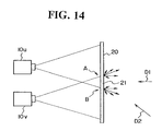
- the photographing by the digital camera is usually performed from the front of the screen. Therefore, a problem is posed that, watching the projected image in a direction deviated from the screen front (for instance in an oblique direction of an upward or downward direction), results in brightness difference in the overlap part from the other areas of the screen due to different directions of projection of the projectors and visual field angle characteristic of the screen, so that the display in the overlap part is pronounced. More specifically, as shown in Fig. 14, when observing image projected from the projectors 10u and lOv onto the screen, the light doses at points A and B are equal in the case of observation in front-ward direction D1, but observation in oblique direction D2 results in that the point A is darker due to less light dose thereat than at the point B.
- the prior art seamless multiple display apparatus has a problem that the display in an overlap part of adjacent images is pronounced.
- the present invention was made in view of the above problems, and it has an object of providing a multiple display apparatus featuring superior display quality without pronounced display in any overlap part.
- a multiple display apparatus for displaying an image with projection of a plurality of images from a plurality of image projecting means onto a screen, wherein: the plurality of image projecting means are disposed such that their images are projected substantially from one point onto the screen.
- a multiple display apparatus for displaying an image with projection of a plurality of images from a plurality of image projecting means onto a screen, and the plurality of image projecting means are disposed such that their images are projected substantially from one point onto the screen and adjacent areas of images projected from the plurality of image projecting means onto the screen overlap one another.
- a multiple display apparatus for displaying an image with projection of a plurality of images from a plurality of image projecting means onto a screen, wherein: the plurality of image projecting means are disposed such that their images are projected substantially from one point onto the screen and the image projecting means include image emitting means for emitting light fluxes of images to be projected onto the screen and reflecting means for reflecting the projection light fluxes emitted from the image emitting means toward the screen.
- a multiple display apparatus for displaying an image with projection of a plurality of images from a plurality of image projecting means onto a screen, and the plurality of image projecting means are disposed such that their images are projected substantially from one point onto the screen, adjacent areas of images projected from the plurality of image projecting means onto the screen overlap one another and the image projecting means include image emitting means for emitting light fluxes of images to be projected onto the screen and reflecting means for reflecting the projection light fluxes emitted from the image emitting means toward the screen.
- Those of the plurality of image projecting means for projecting images onto the screen in the same row in horizontal direction are disposed horizontally, whereby images of light fluxes emitted from horizontally arranged predetermined image emitting means are projected via the reflecting means onto the screen in a predetermined area of the same row in horizontal direction; and those of the plurality of image projecting means for projecting images onto the screen in the same column in vertical direction are disposed vertically, whereby images of light fluxes emitted from vertically arranged predetermined image emitting means are projected via the reflecting means onto the screen in a predetermined area of the same column in vertical direction.
- Those of the plurality of image projecting means for projecting images onto the screen in the same row in horizontal direction are disposed vertically, whereby images of light fluxes emitted from vertically arranged predetermined image emitting means are projected via the reflecting means onto the screen in a predetermined area of the same row in horizontal direction; and those of the plurality of image projecting means for projecting images onto the screen in the same column in vertical direction are disposed vertically, whereby images of light fluxes emitted from vertically arranged predetermined image emitting means are projected via the reflecting means onto the screen in a predetermined area of the same column in vertical direction.
- An area of the reflecting means of an image projecting means, on which the light flux projected from an adjacent image projecting means onto the screen is partly incident, is constructed such as to transmit part of the incident light.
- a multiple display apparatus for displaying an image with projection of a plurality of images from a plurality of image projecting means onto a screen
- the plurality of image projecting means are disposed such that their images are projected substantially from one point onto the screen
- the plurality of image projecting means each include an image generating means for generating an image to be projected onto the screen
- a lens provided between the image generating means and the screen and those of the plurality of image projecting means, which do not regularly face the screen, are constructed such that the image surfaces of their image generating means are tiltable in vertical direction with respect to the lens axis.
- a multiple display apparatus for displaying an image with projection of a plurality of images from a plurality of image projecting means onto a screen, and the plurality of image projecting means are disposed such that their images are projected substantially from one point onto the screen and adjacent areas of images projected from the plurality of image projecting means onto the screen overlap one another
- the plurality of image projecting means each include an image generating means for generating an image to be projected onto the screen, and a lens provided between the image generating means and the screen, and those of the plurality of image projecting means, which do not regularly face the screen, are constructed such that the image surfaces of their image generating means are tiltable in vertical direction with respect to the lens axis.
- the multiple display apparatus further comprises: detecting means for detecting a spatial frequency from an image obtained by photographing the image projected onto the screen; a computing means for obtaining the tilting angle of the image surface of the image generating means on the basis of the detection result by the detecting means; and a tilting control means for causing tilting of the image surface of the image generating means on the basis of the tilting angle obtained by in the computing means.
- a multiple display apparatus for displaying an image with projection of images from a plurality of image projecting means onto a screen, wherein: a light dose limiting means for limiting the light dose in an overlap area of the images projected from the plurality of image projecting means onto the screen, is provided between the image projecting means and the screen.
- the light dose limiting means has areas, in which transmitted light dose increases gradually from a point to another.
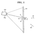
- Fig. 1 is a schematic view showing the basic construction of the first embodiment of seamless multiple display apparatus.
- the apparatus comprises a plurality of image projecting means (although liquid crystal projectors 10p and 10q being shown as image projecting means, the apparatus actually comprises m ⁇ n image projecting means) disposed such that image is projected substantially from one point onto a screen 20.
- the projecting directions (or directivities) of the light fluxes it is possible to have the projecting directions (or directivities) of the light fluxes to be substantially the same in overlap part 21 of adjacent images. It is thus possible to obtain a multiple display apparatus capable of reducing the brightness difference in the overlap part 21 (i.e., making the light dose at point A and B in Fig. 21 to be equal) and ensuring excellent display quality free from pronounced display in the overlap part. Also, since image is projected substantially from one point onto the screen, it is possible to construct conforming Fresnel lens or renticular and increase the screen luminance.
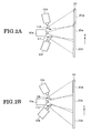
- Fig. 2A schematically shows an example of arrangement of image projecting means (i.e., projectors 10d, 10e and 10f and reflectors lid and llf) for displaying images on the screen in the same row in the horizontal (i.e., X) direction.
- image projecting means for displaying images of the central row are shown.
- the opposite side, i.e., left and right, projectors 10d and 10f are tilted toward the projector 10e, and light fluxes emitted from the projectors 10d and 10f are reflected by reflectors lid and llf such that the projected light fluxes from the individual image projecting means are generated substantially from one point.
- Fig. 2B schematically shows an example of arrangement of image projecting means (i.e., projectors 10b, 10e and 10h and reflectors 11b and 11) for displaying images on the screen in the same column in the vertical (i.e., Y) direction.
- image projecting means for displaying images of the central column are shown.
- the upper and lower projectors 10b and 10h are tilted toward the projector 10e, and light fluxes emitted from the projectors 10b and 10h are reflected by reflectors 11b and llh such that the projected light fluxes from the individual image projecting means are substantially generated from one point.
- the projectors 10a and 10c are tilted toward the projector 10e, and the projectors 10g and 10i, like the projector 10h, are tilted toward the projector 10e. That is, as for the projectors 10a, 10c, 10g and 10i, two reflectors are used for reflection in the horizontal and vertical directions.
- the light dose may be corrected by using such means as ND filter for correcting the brightness deviations among the individual image projecting means.
- nine image projecting means are arranged with the reflectors such that the images from them are projected substantially from one point onto the screen. It is thus possible to let the light be projected substantially in the same direction in the overlap part of adjacent images, and it is thus possible to eliminate outstanding display in the overlap part.
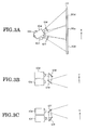
- Figs. 3A to 3C are schematic views showing a second construction example of the embodiment.
- Fig. 3A schematically shows image projecting means (i.e., projectors 10d, 10e and 10f and reflector 12d and 12f) for displaying images on the screen in the same row in the horizontal (i.e. X) direction.
- image projecting means for displaying images of the central row are shown.
- Fig. 3B is a schematic side view of the arrangement of the projectors 10d and 10e and reflector 12d shown in Fig. 3A
- Fig. 3C is a schematic side view showing the arrangement of the projectors 10e and 10f and reflector 12f shown in Fig. 3A.
- the projectors 10d, 10e and 10f are disposed such that they overlap each other.
- a certain reflector in the image projecting means partly overlap part of the projection area of the other image projecting means.
- the projectors have a certain size, a case may arise, in which it is difficult to have the projected light fluxes from the individual image projecting means to be generated from one point.
- the projectors lOd and 10f for displaying the left and right images are disposed one below the other (i.e., in the vertical direction) with respect to the projector 10a for displaying the central image, and the light fluxes emitted from the projectors 10d and 10f are reflected by the reflectors 12d and 12f (each of a dual structure).
- the projected light fluxes reflected by the reflectors 12d and 12f are generated substantially from the same horizontal plane as the emitted light flux from the projector 10e.
- the individual projectors are disposed such that they overlap one above another and, as in the case of Fig. 2B, tilted in the vertical direction.
- the plurality of projectors for displaying images on the screen in the same row in the horizontal direction are disposed one above another, it is possible to have the projected light flux from the individual image projecting means substantially ideally generated from one point.
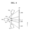
- Fig. 4 is a schematic view showing a third construction example of the embodiment.
- the part of the reflector of a certain image projecting means may produce fog on part of the reflector of a different image projecting means.
- the individual projectors since the individual projectors have a certain size, it is difficult to have the projected light fluxes from the individual image projecting means generated from one point.
- the reflector in an area of the reflector of a certain image projecting means, in which the light flux from an adjacent image projecting means is incident, the reflector is accordingly constructed such that it partly transmits light.
- a partial area H of each of the reflectors 13d and 13f constituting the left and right ones of the image projecting means for displaying images on the screen 20 in one row in the horizontal direction is a half mirror.
- part of the light flux emitted from the central projector 10a, that is incident on the area H is transmitted through the reflectors 13 d and 13f, while part of the light fluxes emitted from the left and right projectors 10d and 10f, that is incident on the area H, is reflected by the reflectors 13d and 13f.
- projected light fluxes are attenuated in a predetermined ratio (for instance 1/2) are combined, and the resultant combined or projected light flux is projected onto the screen.
- the structure of the area H may be made such that it has a plurality of small holes, and a reflecting surface on the side of the left and right projectors 10d and 10f and a shielded surface on the side of the central projector 10a.
- the reflectors 13d and 13f are preferably made to be somewhat thick so that the projected light is attenuated to a certain extent while passing through the holes.
- each reflector since a partial area of each reflector has a half mirror or like structure, it is possible to have the projected light fluxes from the individual image projecting means substantially ideally generated from one point.
- the image projecting means involving the upwardly and downwardly or left-wardly and right-wardly tilted projected light flux directions leads to differences of the distances of projection to the screen.
- Fig. 5 is a schematic view showing the fourth construction example of the embodiment.
- Fig. 6 is a view showing the scopes of projection of images from projectors onto screen.
- any other one than the projector for displaying image on the central screen area i.e., a projector 10 not regularly facing the screen 20, as shown in Fig. 5, a difference of the distance of projection to the screen 20 is produced. Therefore, out-of-focus images are displayed on the screen 20 in portions thereof out of the object field depth.
- the image generating means (i.e., liquid crystal panel 15) of the projector 10 is vertically tiltable by a desired angle from the axis of lens 16.
- the liquid crystal panel 15 i.e., image surface thereof
- trapezoidal distortion is generated in the other areas than the central area 20e).
- the adjustment may be performed automatically with the system as shown in Fig. 5, although it is possible that the user adjusts the tilting by watching the image projected onto the screen 20.
- the automatic tilting adjustment will now be described.
- An image containing harmonic components of dots, resolution analysis chart, etc., is projected from the projector 10 onto the screen 20, and the projected image is photographed by a digital camera 51.
- a spatial frequency detecting means 52 measures frequency components of the projected image.
- a calculating means constituted by a CPU 53 and a memory 54 calculates the tilting angle of the liquid crystal panel 15.
- the calculated tilting angle data is fed out to a tilting control means 55 including a motor. Receiving the tilting angle data, the tilting control means 55 causes tilting of the liquid crystal panel 15.
- the above system performs an operation like so-called "mountain climbing AF" which is usually employed in cameras.
- the above sequence of operations is performed a certain number of times by feed-back so as to tilt the liquid crystal panel 15 to obtain a display containing maximum harmonic components.
- simultaneous projection of the overlap part of adjacent images may lead to difficulty of judging which projector is in out-of-focus state. Accordingly, the individual projectors may be adopted to be adjusted sequentially instead of simultaneously adjusting projectors for projecting images onto adjacent areas.
- trapezoidal distortion is generated in the projection of image from image projecting means involving upwardly and downwardly or left-wardly and right-wardly tilted projected light flux directions.
- Such trapezoidal distortion can be corrected by a method disclosed in, for instance, Japanese Patent Laid-Open No. 9-326981. This correction method will now be described with reference to Fig. 7.
- the system shown in Fig. 7 largely comprises a controller unit 101, a projector 108 and a digital camera 109.
- the digital camera 109 is actually disposed near the position of an image-watching person, so that it can photograph projected image on the screen.
- an image switching means 106 is switched to project a reference image generated in a reference image generator 105 onto the screen.
- the digital camera 109 photographs the projected reference image, and feeds out the obtained image data to a parameter calculator 104.
- the parameter calculator 104 calculates a parameter for determining the disposition of projectors.
- the calculated parameter is stored in a parameter memory 103, and read out, when desired, to be fed to an image divider/processor 102.
- the image divider/processor 102 corrects the input image data by using the read-out parameter, and feed out corrected data thus obtained via a D/A converter 107 to the projectors 108.
- an overlap part is generated in adjacent images projected from the individual projectors onto the screen.
- a problem is thus posed in that the overlap part becomes brighter than the other areas because of the incidence of light fluxes from two to four projectors on the overlap part.
- the overlap part becomes brighter than the other parts because the liquid crystal projectors transmit even very slight light.
- a light dose limiting means 30 for limiting the light dose in the overlap part 21 between a plurality of image projecting means (i.e., although liquid crystal projectors lOr and 10s in Fig. 8 actually m X n image projecting means are provided) and screen 20.
- the light dose limiting means 30 is constituted by a central shielded area 30a and opposite side gradation areas 30b with transmission light dose gradually increasing toward the outer side.
- the gradation areas are constituted by ND (neutral density) filters.
- ND neutral density
- the light dose limiting means 30 is provided at the crossing point of the light fluxes from the projectors lOr and 10s, it is also possible to dispose the light dose limiting means on the projector side of the crossing point. In this case, two light dose limiting means are provided for the respective projectors.
- the gradation characteristic which may be straight slope, may also be a curved line from the consideration of the matching with the image correction.
- the light dose limiting means may be obtained by means of deposition, printing and painting on a base of glass, acrylic acid, etc. It is also possible to obtain the means by printing on a film of OHP, acetate, etc. or on paper, and applying the printed film or paper sheet on a highly transparent base of glass, acrylic acid, etc.
- Fig. 12 shows a reflective multiple display apparatus, which is provided for reducing the thickness of the apparatus.
- a reflector 40 is disposed between the projector 10 and screen 20.
- a light dose limiting means having a shielded area and gradation areas may also be provided on the reflector 40.
- the distance between the screen 20 and the reflector 40 varies with the position of reflection, and the sizes of the shielded and gradation areas are varied.
- the light dose limiting means may be constituted solely by the shielded area and the gradation areas constituted by the ND filters as shown in Fig. 9. In this case, however, if ends of the ND filters are found in the screen, a problem of diffraction or the like may arise. Accordingly, it is possible to form a shielded area and gradation areas by printing or like means on a transparent sheet of such size as to cover the full screen.
- the overlap part of adjacent images may be made non-pronounced, and it is thus possible to obtain a multiple display apparatus capable of ensuring excellent display quality.
Landscapes
- Engineering & Computer Science (AREA)
- Multimedia (AREA)
- Signal Processing (AREA)
- Physics & Mathematics (AREA)
- General Physics & Mathematics (AREA)
- Projection Apparatus (AREA)
- Transforming Electric Information Into Light Information (AREA)
- Stereoscopic And Panoramic Photography (AREA)
- Liquid Crystal (AREA)
Abstract
Description
Claims (13)
- A multiple display apparatus for displaying an image with projection of a plurality of images from a plurality of image projecting means onto a screen, wherein:
the plurality of image projecting means are disposed such that their images are projected substantially from one point onto the screen. - A multiple display apparatus for displaying an image with projection of a plurality of images from a plurality of image projecting means onto a screen, and the plurality of image projecting means are disposed such that their images are projected substantially from one point onto the screen and adjacent areas of images projected from the plurality of image projecting means onto the screen overlap one another.
- A multiple display apparatus for displaying an image with projection of a plurality of images from a plurality of image projecting means onto a screen, wherein:
the plurality of image projecting means are disposed such that their images are projected substantially from one point onto the screen and the image projecting means include image emitting means for emitting light fluxes of images to be projected onto the screen and reflecting means for reflecting the projection light fluxes emitted from the image emitting means toward the screen. - A multiple display apparatus for displaying an image with projection of a plurality of images from a plurality of image projecting means onto a screen, and the plurality of image projecting means are disposed such that their images are projected substantially from one point onto the screen, adjacent areas of images projected from the plurality of image projecting means onto the screen overlap one another and the image projecting means include image emitting means for emitting light fluxes of images to be projected onto the screen and reflecting means for reflecting the projection light fluxes emitted from the image emitting means toward the screen.
- The multiple display apparatus according to claim 3 or 4, wherein:those of the plurality of image projecting means for projecting images onto the screen in the same row in horizontal direction are disposed horizontally, whereby images of light fluxes emitted from horizontally arranged predetermined image emitting means are projected via the reflecting means onto the screen in a predetermined area of the same row in horizontal direction; andthose of the plurality of image projecting means for projecting images onto the screen in the same column in vertical direction are disposed vertically, whereby images of light fluxes emitted from vertically arranged predetermined image emitting means are projected via the reflecting means onto the screen in a predetermined area of the same column in vertical direction.
- The multiple display apparatus according to claim 3 or 4, wherein:those of the plurality of image projecting means for projecting images onto the screen in the same row in horizontal direction are disposed vertically, whereby images of light fluxes emitted from vertically arranged predetermined image emitting means are projected via the reflecting means onto the screen in a predetermined area of the same row in horizontal direction; andthose of the plurality of image projecting means for projecting images onto the screen in the same column in vertical direction are disposed vertically, whereby images of light fluxes emitted from vertically arranged predetermined image emitting means are projected via the reflecting means onto the screen in a predetermined area of the same column in vertical direction.
- The multiple display apparatus according to claim 3 or 4, wherein an area of the reflecting means of an image projecting means, on which the light flux projected from an adjacent image projecting means onto the screen is partly incident, is constructed such as to transmit part of the incident light.
- A multiple display apparatus for displaying an image with projection of a plurality of images from a plurality of image projecting means onto a screen, wherein:
the plurality of image projecting means are disposed such that their images are projected substantially from one point onto the screen, the plurality of image projecting means each include an image generating means for generating an image to be projected onto the screen, and a lens provided between the image generating means and the screen and those of the plurality of image projecting means, which do not regularly face the screen, are constructed such that the image surfaces of their image generating means are tiltable in vertical direction with respect to the lens axis. - A multiple display apparatus for displaying an image with projection of a plurality of images from a plurality of image projecting means onto a screen, and the plurality of image projecting means are disposed such that their images are projected substantially from one point onto the screen and adjacent areas of images projected from the plurality of image projecting means onto the screen overlap one another, wherein:
the plurality of image projecting means each include an image generating means for generating an image to be projected onto the screen, and a lens provided between the image generating means and the screen, and those of the plurality of image projecting means, which do not regularly face the screen, are constructed such that the image surfaces of their image generating means are tiltable in vertical direction with respect to the lens axis. - The multiple display apparatus according to claim 8 or 9, wherein in the focus adjustment of the images projected from the image projecting means onto the screen by adjusting the tilting angles of the image surfaces, no image is projected from the image projecting means adjacent to the image projecting means under adjustment onto the screen.
- The multiple display apparatus according to claim 8 or 9, which further comprises:detecting means for detecting a spatial frequency from an image obtained by photographing the image projected onto the screen;a computing means for obtaining the tilting angle of the image surface of the image generating means on the basis of the detection result by the detecting means; anda tilting control means for causing tilting of the image surface of the image generating means on the basis of the tilting angle obtained by in the computing means.
- A multiple display apparatus for displaying an image with projection of images from a plurality of image projecting means onto a screen, wherein:
a light dose limiting means for limiting the light dose in an overlap area of the images projected from the plurality of image projecting means onto the screen, is provided between the image projecting means and the screen. - The multiple display apparatus according to claim 12, wherein the light dose limiting means has areas, in which transmitted light dose increases gradually from a point to another.
Applications Claiming Priority (4)
| Application Number | Priority Date | Filing Date | Title |
|---|---|---|---|
| JP33162799 | 1999-11-22 | ||
| JP33162799 | 1999-11-22 | ||
| JP2000072857 | 2000-03-15 | ||
| JP2000072857A JP2001215642A (en) | 1999-11-22 | 2000-03-15 | Multi display device |
Publications (2)
| Publication Number | Publication Date |
|---|---|
| EP1102495A2 true EP1102495A2 (en) | 2001-05-23 |
| EP1102495A3 EP1102495A3 (en) | 2005-04-06 |
Family
ID=26573912
Family Applications (1)
| Application Number | Title | Priority Date | Filing Date |
|---|---|---|---|
| EP00125229A Withdrawn EP1102495A3 (en) | 1999-11-22 | 2000-11-22 | Multiple display apparatus |
Country Status (3)
| Country | Link |
|---|---|
| US (1) | US6561651B1 (en) |
| EP (1) | EP1102495A3 (en) |
| JP (1) | JP2001215642A (en) |
Cited By (4)
| Publication number | Priority date | Publication date | Assignee | Title |
|---|---|---|---|---|
| WO2006014598A3 (en) * | 2004-07-08 | 2006-06-15 | Imax Corp | Equipment and methods for the display of high resolution images using multiple projection displays |
| US7193654B2 (en) | 2000-07-03 | 2007-03-20 | Imax Corporation | Equipment and techniques for invisible seaming of multiple projection displays |
| US7224411B2 (en) | 2000-03-31 | 2007-05-29 | Imax Corporation | Digital projection equipment and techniques |
| CN106647130A (en) * | 2017-03-07 | 2017-05-10 | 海信集团有限公司 | Back-projection splicing unit and system, and back-projection splicing unit adjusting method |
Families Citing this family (23)
| Publication number | Priority date | Publication date | Assignee | Title |
|---|---|---|---|---|
| US6814443B2 (en) * | 2001-09-26 | 2004-11-09 | Digital Advertising Network Inc | Image projection system and its method of use |
| US6719433B1 (en) * | 2003-01-02 | 2004-04-13 | Richard S. Belliveau | Lighting system incorporating programmable video feedback lighting devices and camera image rotation |
| US7210798B2 (en) * | 2003-01-17 | 2007-05-01 | High End Systems Inc. | Image projection lighting device and control system |
| US20040150649A1 (en) * | 2003-01-30 | 2004-08-05 | Jerry Moscovitch | Method and apparatus for matching multiple displays in a multi-display environment |
| JP3620537B2 (en) * | 2003-05-02 | 2005-02-16 | セイコーエプソン株式会社 | Image processing system, projector, program, information storage medium, and image processing method |
| EP1639833A1 (en) * | 2003-06-13 | 2006-03-29 | Cyviz AS | Method and device for combining images from at least two light projectors |
| US6899433B2 (en) * | 2003-06-19 | 2005-05-31 | Brookhaven Science Associates | Split image optical display |
| US20050110959A1 (en) * | 2003-10-15 | 2005-05-26 | Seiko Epson Corporation | Multi-projection display |
| JP2006047531A (en) * | 2004-08-03 | 2006-02-16 | Seiko Epson Corp | Multi-projection display and projector unit |
| JP2007060118A (en) * | 2005-08-23 | 2007-03-08 | Casio Comput Co Ltd | Projection apparatus and projection control method |
| US7604354B1 (en) | 2006-05-10 | 2009-10-20 | Ligon Thomas R | Three-dimensional projection apparatus using coaxial optical alignment |
| JP5023587B2 (en) * | 2006-07-18 | 2012-09-12 | 富士ゼロックス株式会社 | Image display device and image display method |
| US7954954B2 (en) * | 2007-07-31 | 2011-06-07 | Hewlett-Packard Development Company, L.P. | System and method of projecting an image using a plurality of projectors |
| TWI361935B (en) * | 2007-09-17 | 2012-04-11 | Young Optics Inc | Display and backlight module thereof |
| JP5725724B2 (en) * | 2010-04-01 | 2015-05-27 | キヤノン株式会社 | Projection device |
| KR102220825B1 (en) * | 2013-09-05 | 2021-03-02 | 삼성전자주식회사 | Electronic apparatus and method for outputting a content |
| US20150109536A1 (en) * | 2013-10-17 | 2015-04-23 | Delta Electronics, Inc. | Display apparatus and display method using the same |
| KR101583289B1 (en) * | 2013-12-09 | 2016-01-07 | 씨제이씨지브이 주식회사 | Method for image correction at ovelapped region of image, computer readable medium and executing device thereof |
| JP6525570B2 (en) * | 2014-12-04 | 2019-06-05 | キヤノン株式会社 | Image display system, control device, control method and program |
| JP2020071308A (en) * | 2018-10-30 | 2020-05-07 | パナソニックIpマネジメント株式会社 | Projection type video display system |
| JP7484181B2 (en) * | 2020-01-24 | 2024-05-16 | セイコーエプソン株式会社 | Projector control method, projector, and display system |
| KR20220054492A (en) * | 2020-10-23 | 2022-05-03 | 삼성디스플레이 주식회사 | multi display panel assembled display |
| CN115115506A (en) * | 2021-03-19 | 2022-09-27 | 中强光电股份有限公司 | Projection system and splicing method of multiple projection pictures |
Family Cites Families (18)
| Publication number | Priority date | Publication date | Assignee | Title |
|---|---|---|---|---|
| US3526452A (en) * | 1966-06-27 | 1970-09-01 | Lazare Paul | Optical apparatus |
| JPS60227239A (en) * | 1984-04-26 | 1985-11-12 | Nec Home Electronics Ltd | Video projector system |
| JPS6147901A (en) * | 1984-08-14 | 1986-03-08 | Canon Inc | Light beam splitting mirror for cameras |
| US5300942A (en) * | 1987-12-31 | 1994-04-05 | Projectavision Incorporated | High efficiency light valve projection system with decreased perception of spaces between pixels and/or hines |
| JPH0354540A (en) * | 1989-07-24 | 1991-03-08 | Seiko Epson Corp | multi vision |
| JP2942344B2 (en) * | 1989-11-22 | 1999-08-30 | 旭光学工業株式会社 | projector |
| JPH0413385A (en) * | 1990-04-30 | 1992-01-17 | Shimadzu Corp | High definition projection display device |
| JP2981788B2 (en) * | 1991-07-17 | 1999-11-22 | キヤノン株式会社 | Information processing apparatus using scanning probe microscope, information processing method and surface matching method |
| KR0142783B1 (en) * | 1994-03-19 | 1998-07-15 | 구자홍 | Image correction device and method when projecting the inclined plane of the projector |
| JP2924654B2 (en) * | 1994-07-29 | 1999-07-26 | 日本ビクター株式会社 | Video projector |
| JPH09197582A (en) * | 1996-01-17 | 1997-07-31 | Sony Corp | Seamless panoramic video camera for multi-screen |
| ATE227457T1 (en) * | 1996-01-17 | 2002-11-15 | Seos Ltd | IMAGE PROJECTION SYSTEM FOR LARGE SCREEN DISPLAY |
| EP0786687A1 (en) * | 1996-01-29 | 1997-07-30 | Hughes-Jvc Technology Corporation | Projected image blending for multiple images |
| JP3735158B2 (en) * | 1996-06-06 | 2006-01-18 | オリンパス株式会社 | Image projection system and image processing apparatus |
| GB9619195D0 (en) * | 1996-09-13 | 1996-10-23 | Seos Displays Ltd | Image display apparatus |
| US5956000A (en) * | 1997-05-12 | 1999-09-21 | Scitex Corporation Ltd. | Digital image display system and method |
| JPH11288041A (en) * | 1998-03-03 | 1999-10-19 | Kokubobu Zhongshan Kagaku Kenkyuin | Video seam elimination method and apparatus for combination of multiple projectors |
| US5902030A (en) * | 1998-05-29 | 1999-05-11 | Blanchard; Randall D. | System for displaying images from multiple projectors onto a common screen |
-
2000
- 2000-03-15 JP JP2000072857A patent/JP2001215642A/en active Pending
- 2000-11-21 US US09/718,214 patent/US6561651B1/en not_active Expired - Fee Related
- 2000-11-22 EP EP00125229A patent/EP1102495A3/en not_active Withdrawn
Cited By (6)
| Publication number | Priority date | Publication date | Assignee | Title |
|---|---|---|---|---|
| US7224411B2 (en) | 2000-03-31 | 2007-05-29 | Imax Corporation | Digital projection equipment and techniques |
| US7193654B2 (en) | 2000-07-03 | 2007-03-20 | Imax Corporation | Equipment and techniques for invisible seaming of multiple projection displays |
| WO2006014598A3 (en) * | 2004-07-08 | 2006-06-15 | Imax Corp | Equipment and methods for the display of high resolution images using multiple projection displays |
| US8251512B2 (en) | 2004-07-08 | 2012-08-28 | Imax Corporation | Equipment and methods for the display of high resolution images using multiple projection displays |
| CN106647130A (en) * | 2017-03-07 | 2017-05-10 | 海信集团有限公司 | Back-projection splicing unit and system, and back-projection splicing unit adjusting method |
| CN106647130B (en) * | 2017-03-07 | 2018-09-28 | 海信集团有限公司 | back projection splicing unit, system and back projection splicing unit adjusting method |
Also Published As
| Publication number | Publication date |
|---|---|
| EP1102495A3 (en) | 2005-04-06 |
| US6561651B1 (en) | 2003-05-13 |
| JP2001215642A (en) | 2001-08-10 |
Similar Documents
| Publication | Publication Date | Title |
|---|---|---|
| US6561651B1 (en) | Multiple display apparatus | |
| US6513938B2 (en) | Multi-display device and multi-display system | |
| US8052280B2 (en) | Laser display device branching a modulated laser beam that scans both beams to the same position at the same time on a screen | |
| JP2000122617A (en) | Keystone distortion correction device | |
| US6471355B1 (en) | Image control system | |
| JP2009290412A (en) | Projector and multi-projection system | |
| KR960016286B1 (en) | Image display apparatus of projection type | |
| JP2005189733A (en) | projector | |
| JPH0215A (en) | liquid crystal display device | |
| EP1089119A1 (en) | Projection system and projector | |
| JP4689948B2 (en) | projector | |
| JP3198630B2 (en) | projector | |
| JP2659542B2 (en) | Rear projection type projection TV | |
| US7331679B2 (en) | Reflection unit having a mirror array, and projection display system employing the same | |
| US7300158B2 (en) | Projection display apparatus | |
| JP3199048B2 (en) | projector | |
| JP4474144B2 (en) | Image projection device | |
| KR101827417B1 (en) | Multi-Cube Screen Correcting System and Correcting Method thereof | |
| EP1498773A1 (en) | Projection display apparatus | |
| JP2002296673A (en) | Image projection device | |
| JPH07143506A (en) | Projection display device | |
| JP3797888B2 (en) | Transmission type screen and projection type image display apparatus using the same | |
| JPH06308635A (en) | Multi-sided multi-rear projector, rear projector used for it, and Fresnel lens | |
| JPH04117785A (en) | Multi-screen display device | |
| JP5017837B2 (en) | Image display device |
Legal Events
| Date | Code | Title | Description |
|---|---|---|---|
| PUAI | Public reference made under article 153(3) epc to a published international application that has entered the european phase |
Free format text: ORIGINAL CODE: 0009012 |
|
| AK | Designated contracting states |
Kind code of ref document: A2 Designated state(s): AT BE CH CY DE DK ES FI FR GB GR IE IT LI LU MC NL PT SE TR |
|
| AX | Request for extension of the european patent |
Free format text: AL;LT;LV;MK;RO;SI |
|
| RAP1 | Party data changed (applicant data changed or rights of an application transferred) |
Owner name: OLYMPUS CORPORATION |
|
| PUAL | Search report despatched |
Free format text: ORIGINAL CODE: 0009013 |
|
| AK | Designated contracting states |
Kind code of ref document: A3 Designated state(s): AT BE CH CY DE DK ES FI FR GB GR IE IT LI LU MC NL PT SE TR |
|
| AX | Request for extension of the european patent |
Extension state: AL LT LV MK RO SI |
|
| AKX | Designation fees paid |
Designated state(s): DE |
|
| STAA | Information on the status of an ep patent application or granted ep patent |
Free format text: STATUS: THE APPLICATION IS DEEMED TO BE WITHDRAWN |
|
| 18D | Application deemed to be withdrawn |
Effective date: 20051007 |