-
The present invention relates to a fuel cell apparatus, and in particular, to an
improvement of a so-called PEM type fuel cell apparatus having a polymer solid electrolyte
film. More particularly, the present invention relates to an improvement of a water direct
injection type, in particular, to a fuel cell apparatus with direct spraying of water onto an
air electrode from a nozzle.
-
A cell main body of the PEM type fuel cell apparatus has a structure including a
polymer solid electrolyte film held between a fuel electrode (also called as a hydrogen
electrode in the case of using hydrogen as a fuel electrode) and an air electrode (also called
an "oxygen electrode" or "oxidation electrode" because oxygen is a reaction gas. A
reaction layer including a catalyst is interposed between the air electrode and the electrolyte
film.
-
The fuel cell having the above structure is generated in an electromotive force in the
following manner. More specifically, a fuel gas is supplied to a fuel electrode side
(anode), and then, an oxidation gas is supplied to an air electrode side; as a result,
electricity is generated with the progress of electrochemical reaction, and then, the
electrocity thus generated is picked up by an external circuit.
-
More specifically, a hydrogen ion obtained by the fuel electrode (anode) is moved
in the form of a ion (H3O+) to the air electrode (cathode) side in an electrolyte film
containing water. Moreover, an electron obtained by the fuel electrode (anode) is moved
to the air electrode (cathode) side through an external load, and then reacts with oxygen
contained in an oxidation gas (e.g., air) to generate water. Thus, electric energy generated
by consecutive electrochemical reactions.
-
The present applicant previously proposed a fuel cell apparatus in JP-A- 10-378161.
The fuel cell apparatus has a structure supplying liquid water onto the surface of air
electrode for the purpose of cooling the air electrode having an exothermic reaction so as to
improve power generation performance.
-
In a so-called water direct injection type fuel cell apparatus as proposed in the above
application, feed water is controlled in accordance with temperature of the fuel cell main
body so as to cool the fuel cell main body. On the other hand, a predetermined amount of
process air is constantly supplied to the air electrode. In other words, the air volume
delivered by the air supply system is always constant. Applicants' prior application
describe influence of the sensible heat and latent heat of the water cooling the fuel cell main
body. In this case, the sensible heat is that heat which is removed from the fuel cell main
body without vaporization of the supplied water. On the other hand, the latent heat is heat
which is removed from the fuel cell main body by vaporization of the directly injected
water.
-
It has now been found that the latent heat of water is used to cool the fuel cell main
body, and that the sensible heat makes little contribution to cooling. Therefore, in order to
more effectively use the latent heat of water, in other words, in order to more effectively
cool by vaporizing water supplied to the air electrode, supply amount of process air
supplied to the air electrode, that is, the air volumetric flow rate should be controlled.
Given, such insight applicants now recognize a number of deficiencies in the previously
proposed water direct injection type fuel cell apparatus.
-
More specifically, when the fuel cell main body is operated at a high temperature,
unless the amount of air (predetermined amount of supply) supplied to the air electrode is
sufficient to properly utilize the latent heat of water, the fuel cell dries up and for this
reason, the air temperature becomes high. In such a case, in order to cool the fuel cell
main body, a large amount of water is supplied so as to utilize the latent heat of
vaporization of water. However, in this case, a large capacity pump is required for
supplying the large amount of water. The large capacity pump hinders any attempt to
miniaturize the fuel cell apparatus, and a great amount of power is consumed in driving the
large capacity pump, thus reducing the efficiency of the fuel cell apparatus. Moreover,
when a large amount of water is supplied to the fuel cell, its process air passage fills with
water, or a water membrane is formed on the surface of the air electrode, creating the
possibility that the amount of oxygen necessary for the chemical reaction of the fuel cell
will not be supplied to the air electrode.
-
On the other hand, when the fuel cell main body is operated at a low temperature,
in the case where the air (predetermined amount) supplied to the air electrode is excessive,
the temperature of the fuel cell main body is lowered, and there is a power loss for the fan
which supplies the air.
-
The water evaporated at the air electrode is condensed for recycle by a condenser
together with reaction water and, thereafter, is recovered. The condenser can effectively
condense water when only a small amount of air is to be treated and the temperature of the
air is high, in which case the capacity of the condenser can be small and the condenser
small is size. In the case where the fuel cell main body is operated at a low temperature
and the supply of process air is larger, a larger capacity (large size) condenser is required.
-
The present invention has been made taking the above-described problem in the
prior art into consideration. It is, therefore, an object of the present invention to provide a
fuel cell apparatus, which includes a water supply for supplying water, in liquid form, onto
a surface of an air electrode of a fuel cell.
-
The fuel cell apparatus of the present invention further includes an air supply
controller for varying the amount of process air supplied to the air electrode.
-
In the fuel cell apparatus constructed as described above, the amount of process air
(volumetric flow rate) is variable so that it can be set to the optimum amount, whereby it is
possible to sufficiently and effectively cool using the latent heat of evaporation of water
supplied to the air electrode, i.e., to effectively cool the air electrode, in particular, and the
fuel cell body, in general. The droplet size of the water spray ranges from 50 µm to 500
µm in order to most effectively use latent heat of evaporation of the water. Moreover, it is
desirable that the thickness of the electrolyte film of the fuel cell be less than 200 µm.
-
More specifically, when the fuel cell main body is operated at a high temperature to
reduce the temperature, the amount of air supplied per unit time, (the amount of air passing
through the air chamber A - see FIG. 3) is increased, taking caution that a sufficient
amount of water is supplied. In prior art apparatus wherein the supply of air is fixed the
sensible heat of water is used, and a relatively large quantity of water must be supplied and
for this reason, there are various problems even if the amount of air supplied is increased.
In the present invention, however, almost no problem is caused even if the amount of air
supplied is great. Even then, the load on the air supply device (fan, etc.) is extremely
small as compared with the prior art which uses a greater amount of water.
-
When the fuel cell is operated at a low temperature to increase its operating
temperature, the amount of the air supply is decreased. By doing so, it is possible to
securely increase the temperature of the fuel cell main body, while reducing the power
consumed by the air supply device to the extent possible.
-
Moreover, in the water recycle condenser, as the internal air temperature increases,
the temperature difference between the internal and external air increases and, therefore,
the capacity of the condenser can be made smaller.
-
According to the present invention, the air supply and the water supply are
controlled independently of each other. Therefore, it is possible to independently control
the required amounts of the air and water with the required timing. By doing so, it is
possible to effectively obtain a high output from the fuel cell without being wasteful.
Further, the amounts of air and water exiting the fuel cell apparatus are minimized and,
therefore, it is possible to make the condenser small in size, and to reduce the power
consumption by auxiliary equipment. Furthermore, it is possible to shorten the time
required for start-up.
-
FIG. 1 is a graph showing the relationship between a load (current density) of the
fuel cell apparatus and exhaust air temperature for various stoichiometric ratios. The
stoichiometric ratio is a predetermined amount of air supplied to the air electrode using the
amount of process air including oxygen theoretically consumed in the fuel cell reaction as a
reference. Therefore, in the case of the stoichiometric ratio 1, the theortectical required
minimum amount of air is supplied. In the case of the stoichiometric ratio 2, the amount of
air supplied is twice that of stoichiometric ratio 1.
-
As seen from the graph shown in FIG. 1, as the stoichiometric ratio becomes
smaller, that is, as the amount of air supply is reduced, the fuel cell apparatus is operated
at a higher temperature in order to obtain the same load. The higher the operating
temperature of the fuel cell apparatus, the higher the efficiency becomes. Moreover, the
exhaust air temperature is increased by the high temperature operation, so that the capacity
of the condenser can be made smaller. Therefore, it is preferable that the fuel cell main
body be operated at the highest temperature maintaining a required load. The load and the
temperature of the fuel cell main body are uniquely determined by the stoichiometric ratio;
therefore, one of the load and temperature is monitored, and then, the stoichiometric ratio,
that is, the amount of air supply, more specifically, the air flow rate at the air chamber
inlet, is determined.
-
However, in a conventional fuel cell, there are various limits on the operating
temperature of the fuel cell main body and on the stoichiometric ratio (amount of air
supply). For example, in order to reliably prevent the fuel cell main body from becoming
burned, the operating temperature of the fuel cell main body needs to be set to 100 to 80°C
or less, for example. Moreover, according to the research by the present inventors,
operation of the fuel cell main body was impossible under the conditions on the upper side
of the broken line L shown in FIG. 1. It is theorized that this observed inoperativeness is
due to the following reasons. More specifically, when the amount of air supply is small
(when the volume of air is small), air is not efficiently supplied to the air electrode due to
resistance within the air supply passage and the gas diffusion layer, catalyst powder and the
like.
-
Therefore, in FIG. 1, for example, the fuel cell main body is operable in a range of
80°C or less and on the lower side of the broken line L. Considering its efficiency, it is
preferable that the fuel cell main body be operated at the highest temperature in the above
operable range.
-
In a vehicle fuel cell apparatus having a severe load fluctuation, the amount of air
supply is changed in accordance with the required load. At that time, simultaneously, the
temperature of the fuel cell main body is detected, and then, preferably, the amount of air
supply is adjusted so that the highest temperature realizing the required load, that is, the
minimum stoichiometric ratio can be obtained.
-
On the other hand, if the fuel cell apparatus is used in an environment wherein there
is no load variation, only temperature of the fuel cell main body need be monitored, and
then, only when the temperature changes is the amount of air supply adjusted so that the
temperature is controlled as desired. More specifically, where the temperature of the fuel
cell main body becomes lower than a desired temperature range, the amount of air supply
is decreased so as to reduce the cooling effect of the latent heat of evaporation of water.
On the other hand, in the case where the temperature of the fuel cell main body becomes
higher than a desired temperature range, the amount of air supply is increased so as to
enhance the cooling effect of the latent heat of evaporation of water.
-
The external environment and the performance of auxiliary equipment, impose
various limits on the operating conditions of the fuel cell apparatus. The operating
conditions of the fuel cell main body are limited to a range indicated by the square in the
operable conditions shown in FIG. 1. In this range, the operating temperature of the fuel
cell main body does not exceed the line of the stoichiometric ratio 1. The amount of air
supply is always maintained at least at the amount corresponding to stoichiometric ratio 1
in order to ensure continuous operation of the fuel cell. Therefore, there is no need for
monitoring the temperature of the fuel cell. Accordingly, only load is monitored so that
the minimum amount of air capable of outputting the required load is supplied.
-
In all of the scenarios described above, the amount of water is continuously supplied
to the air electrode is sufficient to allow for the water which is vaporized by the heat of the
fuel cell and to ensure that liquid water is always present on the air electrode and in its
surroundings (i.e., air chamber) during an operation of the fuel cell apparatus.
-
As described above, water always present in the air electrode, therefore, the latent
heat of vaporization of water can be effectively used. As a result, it is possible to reduce
the cooling plates in a stack of the fuel cell main body, or to omit the cooling plate
altogether. However, where it is impossible to reliably provide for vaporization of a
sufficient amount of water, it is preferable that the stack of the fuel cell main body be
provided with a cooling plate, cooling pipe or other cooling device. The heat generated
within the stack is removed to the exterior by a heat medium (usually, water) circulating
through the cooling device, and the heat thus removed may be used for interior heating or
the like (co-generation).
-
In the operation described above, the process air is substantially uncompressed, as
supplied to the air electrode. However, the present invention may be applied to a fuel cell
apparatus which includes a pressurized oxidizing gas supply system. The pressurized
oxidizing gas supply may include a compressor or the system may become a pressurized
(higher than atmospheric pressure) simply by resistance to gas flow within the system
piping.
-
The temperature of the fuel cell main body may be measured by a thermometer
attached to the fuel cell main body. As shown in FIG. 1, the temperature of exhaust air is
measured, and thereby, it is possible to indirectly measure the temperature of the fuel cell
main body. It is preferable to measure the temperature of the air just after being exhausted
from the fuel cell main body.
-
The load of the fuel cell main body is a product of current and the voltage between
its electrodes. The actual load presently output by the fuel cell main body is detected, and
then, the detected load is used as a reference parameter to control the amount of process
air. The demanded load for the fuel cell apparatus is detected, for example, as a speed,
torque or accelerator opening, and then, used as the control parameter.
-
The above and other objects and technical advantages of the present invention will
be readily apparent from the following description of the preferred embodiments of the
invention read in conjunction with the accompanying drawings, in which:
- FIG. 1 is a graph showing the relationship between current density (load) of a fuel
cell main body, air exhaust temperature (temperature of the main body itself) and the
stoichiometric ratio (amount of air supply);
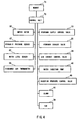
- FIG. 2 is a schematic view showing structure of a fuel cell apparatus according to
one embodiment of the present invention;
- FIG. 3 is a cross sectional view of the basic structure of the fuel cell apparatus;
- FIG. 4 is a schematic view showing a control system for the fuel cell apparatus;
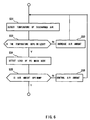
- FIG. 5 is a flowchart showing a main routine for operation of the fuel cell
apparatus;
- FIG. 6 is a flowchart of a routine for operation of an air supply system;
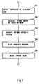
- FIG. 7 is a flowchart of a routine for operation of a water supply system;
- FIG. 8 is a graph showing a relationship between water injection and hydraulic
pressure;
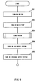
- FIG. 9 is a flowchart of a control routine for fuel cell start up;
- FIG. 10 is a schematic view showing the structure of a fuel cell apparatus according
to another embodiment of the present invention;
- FIG. 11 is a schematic view of a control system for the fuel cell apparatus shown in
FIG. 10; and
- FIG. 12 is a flowchart of a routine for operation of an air supply system for the fuel
cell apparatus shown in FIG. 10.
-
-
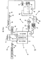
FIG. 2 schematically shows the structure of a fuel cell apparatus 1 according to one
embodiment and FIG. 3 shows a basic unit of a fuel cell unit 10 of the apparatus 1..
-
As shown in FIG. 2, the fuel cell apparatus 1 is schematically composed of a fuel
cell main body 10, a hydrogen gas (fuel gas) supply system 20, an air supply system 30
and a water supply system 40.
-
A unit fuel cell has a main body 10 including a polymer solid electrolyte film 12
held between an air electrode 11 and a fuel electrode 13. The fuel cell apparatus 1,
consists of a plurality of unit fuel cells arranged in a fuel cell stack. Air manifolds 14 and
15 for intake and exhaust of air are individually formed above and below the air electrode
11. The upper-side air manifold 14 has a hole for attaching a nozzle 41. There is a limit
to the injection angle of water injected from the nozzle 41, and in order to form a water
mist and to spray it over the entire surface of the air electrode 11, a predetermined
minimum distance is required between the nozzle 41 and the air electrode 11. Therefore,
the manifold 14 becomes relatively high. On the other hand, the lower-side air manifold
15 is constructed so as to effectively discharge collected water.
-
The nozzle may be mounted on the side of the manifold 14. The water injected
from the nozzle is sprayed throughout the manifold 14, and is thereby, spread over the
entire surface of the air electrode 11. The nozzle is provided on the side of the manifold
14 so that a low manifold can be employed. By doing so, it is possible to miniaturize the
fuel cell main body.
-
Preferably, the nozzle injects water directly toward the surface of the air electrode.
By doing so, regardless of an amount of air supply, it is possible to supply a predetermined
amount of water onto the surface of the air electrode. More specifically, the amount of air
supply and the amount of supply water can be independently controlled. According, when
a large amount of air (air volume) is supplied in start up, a desired amount of water can be
reliably supplied onto the surface of the air electrode, and it is thereby, possible to reduce
the start-up time.
-
In contrast, in systems wherein water is introduced into an air flow and supplied to
the air electrode wafted on the air flow, the amount of air supply and the amount of water
supply can not be controlled independently from each other. A change in the amount of air
supply and the amount of water supply is not always requested at the same time, and there
are situations wherein their changes are independently required. For example, in the case
where a change is required with respect to only air supply, when the amount of water
supply is changed, the control response of the fuel cell main body becomes late and,
further, there is a possibility of a reduced output of the fuel cell apparatus.
-
On the contrary, in the independent supply type employed in the present invention,
a required amount of water and/or air is supplied at the proper times and, therefore, it is
possible to effectively control the fuel cell main body. Moreover, because the water supply
and the air supply are independently controlled, it is thereby possible to prevent the air and
water from being wastefully supplied and it is thereby possible to make the condensor small
in capacity.
-
As shown in FIG. 3, the unit fuel cell is composed of the air electrode 11, the solid
polymer electrolyte film 12 and the fuel electrode 13, and is formed like a thin film.
Further, the unit cell is held between a pair of carbon connector plates 16 and 17. The
surface of the connector plate 16 facing the air electrode 11 is formed with a plurality of
grooves 18 for air ventilation. Each groove 18 is formed in a vertical direction so as to
communicate with the manifolds 14 and 15. As a result, a water mist supplied from the
nozzle 41 is supplied to the lower portion of the air electrode 11 along the groove 18.
-
An air chamber A is defined by the circumferential surface of the groove 18 and the
surface of the air electrode 11. An opening portion (upper side in FIG. 3) of the air
chamber A is an air inlet (upstream side opening), and an opening portion (lower side in
FIG. 3) of the air chamber A is an air outlet (downstream side opening). Preferably, a
thermometer is provided so as to detect exhaust temperature at the air outlet. In this
embodiment, a liquid such as water or the like is injected directly into the upstream side
opening. The liquid such as water or the like may be supplied from the downstream side
opening. Moreover, the connector plate may be formed with a through hole extending to
the right and left in FIG. 3 so that the liquid such as water can be supplied to the air
chamber A therefrom. The water supplied in the above manner vaporizes on the surface
constituting the air chamber A (circumferential surface of the groove 18 and the surface of
the air electrode 11, which surfaces easily reach relatively high temperatures).
-
Likewise, the surface of the connector plate 17 facing the fuel electrode 13 is
formed with a groove 19 for passage of hydrogen gas. In this embodiment, a plurality of
grooves 19 is horizontally formed. A fuel chamber B is defined by the circumferential
surface of the groove 19 and the surface of the connector plate 17. Water may be supplied
to the fuel chamber B by the same method as to the air chamber A already described.
-
The air electrode 11 is formed of a water-tight material. If a water film forms on
the air electrode 11, the effective area of the air electrode 11 is reduced and, for this
reason, the material forming the air electrode 11 is required to be highly water repellent..
A gas diffusion layer is used as the material forming the air electrode 11. The gas
diffusion layer is formed by using carbon as a base material, and by a coating, such as C +
PTFE thereon.
-
As the solid polymer electrolyte film 12, a NAFION (Trade name: Dupont
company) thin film may be used.
-
The thickness of the film is not limited so long as reverse osmosis of generated
water from the air electrode side is possible.
-
The fuel electrode 13 is formed of the same material as the air electrode 11, because
it is used common with the other components.
-
In the air electrode 11 and the fuel electrode 13, a known platinum-based catalyst of
a proper thickness is uniformly dispersed on their surfaces in contact with the electrolyte
film 12 in order to facilitate the reaction of oxygen with hydrogen and, thus, is formed as a
catalyst layer of the air electrode 11 and the fuel electrode 13.
-
In this embodiment, a hydrogen bomb made of hydrogen storage alloy is used as the
hydrogen supply 21 of the hydrogen gas supply system 20. Alternatively, a cylinder of
liquid hydrogen may be used. In another alternative water/methanol liquid is reformed and
reacted in a reformer so as to generate a hydrogen rich reforming gas, and then, the
reforming gas is stored in a tank for use as a hydrogen source. Of course, in the case of
using the fuel cell apparatus 1 stationary within a room, hydrogen may be piped in for use
as a hydrogen source.
-
The hydrogen supply device 21 and the fuel electrode 13 are connected by a
hydrogen gas supply passage 22 via a hydrogen supply pressure control valve 23. The
pressure control valve 23 controls the pressure of hydrogen gas supplied to the fuel
electrode 13.
-
Exhaust gas from the fuel electrode 13 is discharged to the exterior or may be
supplied to the air manifold so as to be mixed with incoming air.
-
Atmospheric air is supplied to the air electrode 11 by a fan 38. In FIG. 2,
reference numeral 31 denotes an air supply passage which is connected to the manifold 14
of the air electrode 11. The lower side manifold 15 is connected with an air passage 32 for
circulating or exhausting air passing through the air electrode 11, and an exhaust gas is sent
to an exhaust passage 36 via a condenser 33 for separating water. The amoujnt of exhaust
air discharged from the exhaust passage 36 is controlled by an air exhaust control valve 34.
In this case, the air exhaust control valve 34 is omitted and the exhaust gas may be
discharged to the atmosphere as is.
-
In the air supply system 30, no air compressor is provided and atmospheric pressure
is maintained throughout the whole system.
-
In FIG. 2, reference numeral 39 denotes a thermometer for detecting temperature of
the discharged air.
-
Water separated by the condenser 33 is sent to a tank 42. The tank 42 is provided
with a water level sensor 43 and when a water level in the tank 42 reaches a predetermined
value or less, an alarm 44 is sounded and/or flashed by the water level sensor 43 so as to
inform an operator of a shortage of water. Preferably, operation of the condenser 33 is
variable so as to control the amount of water recovered. More specifically, when water is
short, rotational speed of the fan of the condenser 33 is increased so as to recover a large
amount of water. On the other hand, when the amount of recovered water is excessive, the
rotational speed of the fan of the condenser 33 is decreased or stopped so as to reduce the
amount of water recovered.
-
The water supply system 40 of this embodiment includes a water supply passage 45
from the tank 42 which is connected to the nozzle 41 via pump 46, a hydraulic pressure
sensor 47 and a pressure control valve 48. The pressure of the water is controlled by the
pressure control valve 48 and, thereafter, is sprayed out of the nozzle 41 to thus form a
mist in the air manifold 14. Then, the water mist is supplied onto the entire surface of the
air electrode 11 by spraying, the weight of the mist, an air flow or the like. The control of
supply of water is not limited to the combination of the pressure control valve and the
nozzle.
-
In the above manner, when the water is supplied onto the surface of the air
electrode 11, the supplied water absorbs heat from the surrounding air, the surface of the
air electrode 11 and the surface of the separator, as latent heat as it vaporizes. By doing
so, it is possible to prevent the water content of the electrolyte film 12 from being lost.
-
Moreover, the water supplied to the air electrode 11 absorbs heat from the air
electrode 11 as latent heat and therefore effects the cooling of the air electrode 11. In
particular, in start up, when the water is supplied, it is possible to prevent a film and
catalyst from being damaged by combustion of hydrogen and air.
-
In FIG. 2, reference numeral 50 denotes an ampere meter which measures current
between the air electrode 11 and the fuel electrode 13. The current density shown in FIG.
1 is calculated from a current measured by the ampere meter 50. In this embodiment, a
resistor 51 is constant; therefore, a current between the air electrode 11 and the fuel
electrode 13 is measured, and thereby, the load (= work) on the fuel cell main body 10 can
be calculated.
-
In the case of use of the fuel cell apparatus in a vehicle, current and voltage
between the two electrodes are measured to obtain the load (presently output power of the
fuel cell main body). In the case of a vehicle, it is possible to estimate the power required
of the fuel cell main body from torque or accelerator opening.
-
Operation of the fuel cell apparatus 1 of this embodiment will now be described
with reference to FIGS. 4 and 5.
-
In FIG. 4, the control unit 70 and a memory 73 are commonly housed in a control
box (not shown in the drawings) of the fuel cell apparatus 1. The memory 73 stores a
control program for controlling operations of the control unit 70 (comprising a computer)
and parameter data and look-up tables for executing the various control routines.
-
Control of the hydrogen gas supply system 20 in start-up is executed as step 1 of
FIG. 5. In start-up, hydrogen exhaust valve 25 is closed and hydrogen supply control
valve 23 is adjusted so that hydrogen gas is supplied to the fuel electrode 13 to provide a
predetermined concentration below the explosive limit at the fuel electrode 13. When the
fuel cell apparatus 1 is operated with the hydrogen exhaust valve 25 closed, N2, O2 and the
water of reaction transmitted through the air electrode tend to gradually reduce the partial
pressure of hydrogen consumed in the fuel electrode and to thereby reduce the output
voltage so that a stable voltage can not be obtained. In order to solve this problem, the
hydrogen exhaust valve 25 is opened sufficiently, in accordance with a predetermined
control routine, to exhaust the gas in which the hydrogen partial pressure is reduced and to
thereby allow fresh fuel gas to reach the fuel electrode 13.
-
This predetermined control routine is stored in the memory 73, and the control unit
70 reads it from the memory 73 for control of opening and closing of the hydrogen exhaust
valve 25 and adjustment of the hydrogen supply control valve 23.
-
In this embodiment, the output current is monitored by the ampere meter 50, and
then, when the output current decreases to a predetermined threshold value, the hydrogen
exhaust valve 25 is released for a predetermined time (e.g., one second).
-
Alternatively, the fuel cell apparatus 1 may be operated with the hydrogen exhaust
valve 25 normally closed, and an actual time interval in which the output voltage will start
to decline is predetermined. Then, the opening and closing of the hydrogen exhaust valve
25 is intermittently controlled so that the valve 25 is opened at the end of each time interval
which is substantially the same as the actual time interval or a period slightly shorter than
that.
-
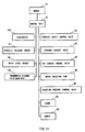
Control of start-up operation of the air supply system 30 is executed as step S3 of
FIG. 5 and will be described below with reference to FIG. 6.
-
In step S31,the thermometer 39 detects the temperature of exhaust air just after
being discharged from the fuel cell main body 10. When the detected temperature exceeds
80°C (step S32), there is the possibility that the fuel cell main body 10 might be burned.
For this reason, rotational speed of the fan 38 is increased so as to increase the amount of
air (step S33), and, it is thereby possible to reduce the temperature of the air electrode 11
which is a heat generator. In this case, of course, a water required for cooling the fuel cell
main body 10, overheated a temperature exceeding 80°C, is supplied to the air electrode
11.
-
In normal operation where the detected temperature is 80°C or less, the load of the
fuel cell main body 10 is detected (step S34) and in this embodiment, the relationship
shown in FIG. 1 is used for control. Therefore, the current between the air electrode 11
and the fuel electrode 13 is detected by the ampere meter 50 and the control unit 70
calculates (operates) a current density from the detected current. Further, the control unit
70 collates the current density value and the temperature detected in step S31 with the
relationship of FIG. 1 stored in the memory 73 in the form of a table.
-
For example, in the case where the relationship between the detected temperature
and the current density is the condition A shown in FIG. 1, the amount of air is reduced,
and then, the operating state of the fuel cell main body 10 is changed to that of condition B
shown in FIG. 1. More specifically, the amount of air supply is decreased to an amount
corresponding to the stoichiometric ratio 2 so as to reduce cooling by latent heat. By doing
so, the fuel cell main body 10 is operated at the highest temperature at which its output
(current density) can be maintained. In this case, in order to effectively increase the
temperature of the fuel cell main body 10, the initial amount of air is preferably made
smaller than that corresponding to the stoichiometric ratio 2 but not below a level where
the fuel cell main body would be short of oxygen, and then, the rate of temperature rise is
increased so as to approach temperature (approximately, 80°C) of the condition B, and
thereafter, the amount of air is made to correspond to the stoichiometric ratio 2.
-
In this case, the memory 73 prestores the relationship between the amount of supply
air (stoichiometric ratio) and rotational speed of fan 38, and the control unit 70 controls the
rotational speed of the fan 38 so that the amount of air corresponds to the required amount.
For example, a servo motor drive type fan may be used as the fan 38.
-
In the case where the current density of the fuel cell main body 10 operating at the
condition B changes to 0.7, the fuel cell main body 10 needs to be operated at the condition
C. In this case, the amount of air is increased up to the amount of air of the condition
C(corresponding to the stoichiometric ratio 5) so as to reduce the temperature of the fuel
cell main body 10 to the temperature (approximately, 70°C) of the condition C.
-
As described above, the operating temperature of the fuel cell main body 10 is
preferably set to the highest possible temperature in the operable range.
-
Start-up of the water supply system 40 executed in step S5 of FIG. 5. Water from
the tank 42 is supplied by using the pump 46. Then, the pressure of the water is adjusted
by an injection pressure control valve 48, and is sprayed from the nozzle 41. By doing so,
the water is supplied to the air electrode 11 in a liquid state (mist). Of course, the injection
pressure control valve 48 may be omitted and, instead, the voltage applied to the pump 46
may be adjusted so as to control the discharge pressure of the pump 46. Using either
method, a desired amount of water is sprayed onto the air electrode 11.
-
The amount of water supply is predetermined in accordance with the temperature of
the fuel cell main body. More specifically, in order to maintain the temperature of the fuel
cell main body at the predetermined temperature, the least amount of water necessary is
supplied. This serves to reduce power consumed by the pump 46 as much as possible. In
this case, when the fuel cell main body becomes less than a predetermined temperature
(e.g., 30°C), the supply of water is then stopped. The memory 73 stores the relationship
between the temperature of the fuel cell main body 10 and the amount of water to be
supplied.
-
In this embodiment, as shown in FIG. 7, the temperature of the exhaust air is first
detected (step S51). Subsequently, an optimum amount of injection water is calculated on
the basis of the detected temperature (step S53) or made by reference to the predetermined
relationship stored in the memory 73.
-
Next, in step S53, an optimum hydraulic pressure corresponding to the optimum
amount of injection water is calculated. For example, the amount of injection water and
the hydraulic pressure have a relationship as shown in FIG. 8, which relationship is
prestored in the memory 73 in the form of an equation or look-up table.
-
In this embodiment, the pump 46 is operated at constant power and hydraulic
pressure at the nozzle 41 is controlled by operation of a pressure control valve 48 in a bypass
49. More specifically, as the opening of the pressure control valve 48 is increased,
the hydraulic pressure at the nozzle 41 is decreased.
-
Therefore, in step S54, the hydraulic pressure sensor 47 detects the hydraulic
pressure applied at the nozzle 41, and then, the pressure control valve 48 is controlled so
that the hydraulic pressure is set to a desired value (optimum hydraulic pressure) by a
feedback control (step S55).
-
Alternatively, with each lapse of a predetermined time interval (e.g., 5 to 10
seconds), the water supply system 40 may be operated at a reset, constant hydraulic
pressure.
-
In start-up of the fuel cell apparatus 1 itself, as shown in FIG. 9, when a switch (not
shown) is turned on (step S91), the pump 46 is turned on (step S93). Subsequently, the
pressure control valve 48 is controlled so that a predetermined amount of injection water is
supplied to the nozzle 41 (step S95). In order to protect the fuel cell main body 10 from an
abnormal reaction, the amount of water sprayed onto the air electrode 11 is set to the
maximum amount.
-
Thereafter, the air supply system 30 is turned on (step S97). At that time, the speed
of the fan 38 is set to the maximum so as to cool the fuel cell main body 10, and thereby,
prevent an abnormal reaction. Subsequently, the hydrogen supply system 20 is turned on
(step S99).
-
The desired output voltage between the air electrode 11 and the fuel electrode 13, is
confirmed and, thereafter, the electric power is output from the apparatus.
-
In the above embodiment, the air supply system 30 may be operated before the start
of operation of the water supply system 40. Moreover, the air supply system 30 may be
operated after the start of operation of the hydrogen supply system 20.
-
However, in this case, the water supply system 40 must be operated before the start
of the hydrogen supply system 20 because air exists in the fuel cell main body 10
regardless of operation of the air supply system 30; and if hydrogen were to be supplied
with the electrolyte film 12 in a dry state, there would be the possibility of abnormal
combustion. In the case where an abnormal amount of heat is generated, in order to
protect the fuel cell main body 10 against damage, water is injected before hydrogen is
supplied whereby the air electrode 11 is wet. By doing so, the abnormal heat is converted
into latent heat by evaporation of water so as to facilitate wetting of the electrolyte film 12,
and thereby, it is possible to prevent the fuel cell main body 10 from being damaged.
-
Another embodiment will now be described below with reference to FIGS. 10 to
12. In this case, like reference numerals are used to designate the same components and
steps as in the above embodiment already described, and details of such duplicated features
are omitted.
-
In the fuel cell apparatus 101 of the embodiments of FIGS. 10-12, a damper 138 is
provided on the downstream side of the fan 38. The fan 38 is driven at a constant
rotational speed and the damper 138 is controlled to regulate an amount of air supply.
Further, a thermometer is attached to the fuel cell main body 10, preferably to the
connector plate on the air electrode side, so as to directly measure temperature of the fuel
cell main body 10. Furthermore, in this embodiment, vehicle accelerator opening is
detected, and the control unit 70 calculates the load required of the fuel cell main body 10
from the detected opening (in FIG. 12, step S134). In this case, in step S134, the control
unit 70 converts the obtained load into a current density so as to use the relationship shown
in FIG. 1.
-
According to the above embodiment, a load required for the fuel cell main body is
read directly from the detected state of the accelerator and, therefore, it is possible to more
quickly control the amount of air supply.
-
Other operations and effects of the above embodiment are the same as those of the
previously-described embodiment.