EP1102304B1 - Particle-optical apparatus including a low-temperature specimen holder - Google Patents
Particle-optical apparatus including a low-temperature specimen holder Download PDFInfo
- Publication number
- EP1102304B1 EP1102304B1 EP01200763A EP01200763A EP1102304B1 EP 1102304 B1 EP1102304 B1 EP 1102304B1 EP 01200763 A EP01200763 A EP 01200763A EP 01200763 A EP01200763 A EP 01200763A EP 1102304 B1 EP1102304 B1 EP 1102304B1
- Authority
- EP
- European Patent Office
- Prior art keywords
- specimen holder
- specimen
- cooling
- conduit
- particle
- Prior art date
- Legal status (The legal status is an assumption and is not a legal conclusion. Google has not performed a legal analysis and makes no representation as to the accuracy of the status listed.)
- Expired - Lifetime
Links
- 238000001816 cooling Methods 0.000 claims description 36
- 238000006073 displacement reaction Methods 0.000 claims description 8
- RYGMFSIKBFXOCR-UHFFFAOYSA-N Copper Chemical compound [Cu] RYGMFSIKBFXOCR-UHFFFAOYSA-N 0.000 description 5
- 229910052802 copper Inorganic materials 0.000 description 5
- 239000010949 copper Substances 0.000 description 5
- 239000007788 liquid Substances 0.000 description 5
- IJGRMHOSHXDMSA-UHFFFAOYSA-N Atomic nitrogen Chemical compound N#N IJGRMHOSHXDMSA-UHFFFAOYSA-N 0.000 description 4
- 238000009835 boiling Methods 0.000 description 2
- 239000004020 conductor Substances 0.000 description 2
- 239000001307 helium Substances 0.000 description 2
- 229910052734 helium Inorganic materials 0.000 description 2
- SWQJXJOGLNCZEY-UHFFFAOYSA-N helium atom Chemical compound [He] SWQJXJOGLNCZEY-UHFFFAOYSA-N 0.000 description 2
- 239000012212 insulator Substances 0.000 description 2
- 229910052757 nitrogen Inorganic materials 0.000 description 2
- 239000012530 fluid Substances 0.000 description 1
- 238000003384 imaging method Methods 0.000 description 1
- 238000005086 pumping Methods 0.000 description 1
- 230000000717 retained effect Effects 0.000 description 1
Images
Classifications
-
- H—ELECTRICITY
- H01—ELECTRIC ELEMENTS
- H01J—ELECTRIC DISCHARGE TUBES OR DISCHARGE LAMPS
- H01J37/00—Discharge tubes with provision for introducing objects or material to be exposed to the discharge, e.g. for the purpose of examination or processing thereof
- H01J37/02—Details
- H01J37/20—Means for supporting or positioning the object or the material; Means for adjusting diaphragms or lenses associated with the support
-
- H—ELECTRICITY
- H01—ELECTRIC ELEMENTS
- H01J—ELECTRIC DISCHARGE TUBES OR DISCHARGE LAMPS
- H01J2237/00—Discharge tubes exposing object to beam, e.g. for analysis treatment, etching, imaging
- H01J2237/20—Positioning, supporting, modifying or maintaining the physical state of objects being observed or treated
- H01J2237/2001—Maintaining constant desired temperature
Definitions
- the invention relates to a particle-optical apparatus, including a manipulable specimen holder for supporting a specimen being studied in the apparatus, and a cooling device for cooling the specimen, which cooling device is provided with a cold source which is connected to the specimen via cooling conduit means, the cooling conduit means provided separately between the end of the specimen holder which is situated inside the apparatus and the cold source.
- a particle-optical apparatus in the form of a SEM including a manipulable specimen holder for supporting a specimen.
- One end of the specimen holder is positioned in a vacuum chamber of the apparatus, and is there connected with a cold source via flexible cooling conduit means in the form of a number of copper strips.
- the cold source in turn is connected to a dewar with a cold fluid, such as liquid nitrogen, at the outside of the apparatus via a heat conducting post.
- a disadvantage of said apparatus is that the copper strips will conduct vibrations from the cold source to the specimen holder. As known to the person skilled in the art such vibrations can easily be induced by the boiling liquid in the dewar, such as boiling liquid nitrogen.
- Another disadvantage of said apparatus is that the strips will exert a force on the specimen holder, which force will change in magnitude and/or direction when the specimen holder takes another position or orientation with respect to the cold source. This may result in difficulties to achieve small positional or orientational changes of the specimen holder with respect to the cold source.
- US patent No. US 4,262,194 a specimen stage for holding specimens, a so-named top-entry specimen stage, is described.
- This stage comprises a gold-plated copper arbor mounted on a stage translation mechanism.
- the stage mechanism is mounted on a lens.
- the arbor is thermally insulated from the stage translation mechanism and connected via leaves of copper to a cold source.
- the copper leaves are intended to provide a more or less flexible connection between arbor and cold source.
- a specimen holder may be placed.
- the specimen stage known from US 4,262,194 is not capable to rotate the sample.
- the time it takes for the specimen stage of US 4,262,194 to reach thermal equilibrium is longer than for prior art stages identified in said patent. Also its equilibrium temperature is higher than that of prior art stages identified in said patent.
- the particle-optical apparatus is characterised in that the cooling conduit means include a flexible thermal conduit that is connected to the end of the specimen holder which is situated inside the apparatus, and the apparatus is provided with displacement means for displacing the flexible thermal conduit in such a manner that the displacement of the specimen holder relative to the flexible thermal conduit is reduced. It cannot be precluded that, despite its flexibility, said flexible thermal conduit still exerts inadmissible forces on the specimen holder. Therefore it is useful to displace the flexible thermal conduit in approximately the same way upon displacement of the specimen holder, so that no forces can be induced by deformation of the conduit.
- the displacement means in a further embodiment of the invention include a rotation unit which is separate from the specimen holder and whose axis of rotation substantially coincides with the axis of rotation of the specimen holder, one end of the flexible thermal conduit being connected to said rotation unit whereas its other end is connected to the end of the specimen holder which is situated inside the apparatus.
- a separate rotation unit can thus be provided which is controlled in known manner so that the rotation of this unit follows that of the specimen holder without forces being exerted on the specimen holder. This is possible, for example by utilizing a servo mechanism which measures the angular rotation of the specimen holder and controls a motor of the rotation unit. In that case no or only negligibly small deformation of the conduit will occur.
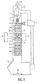
- the electron microscope shown in Fig. 1 includes an electron source 1 with an electron-emissive element 2, a beam alignment system 3, a beam diaphragm 4, a condensor lens 6, an objective lens 8, a beam scanning system 10, an object space 11, a diffraction lens 12, an intermediate lens 14, a projection lens 16 and an electron detector 18.
- the objective lens 8, the intermediate lens 14 and the projection lens 16 together constitute an imaging lens system.
- the above elements are accommodated in a housing 17 with an electrical supply lead 19 for the electron source, a viewing window 15 and a vacuum pumping device 5.
- a specimen holder 7 which is coupled to a control unit 9 for moving the specimen holder 7.
- the specimen holder has been introduced via an opening in the housing 17 of the apparatus.
- a loading/unloading unit 13, also called transport unit, has been introduced via another opening in the housing of the apparatus which is situated opposite the opening for the specimen holder.
- a cooling device for cooling the specimen is not shown in Fig. 1 , but will be described with reference to the Figs. 2, 3 and 4 .
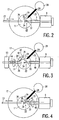
- Fig. 2 is a more detailed diagrammatic horizontal cross-sectional view of the column of the electron microscope shown in Fig. 1 .
- the housing 17 of the electron microscope encloses the object space 11 which accommodates the end 20 of the specimen holder 7 which is situated in the apparatus.
- the object space 11 also accommodates a part of a transport unit 13 which is only diagrammatically shown in Fig. 2 .
- the object space 11 accommodates one end 24 of a cooling finger 22, the other end 26 of which is in contact with the contents of a dewar vessel 28, for example with liquid helium.
- the end 24 of the cooling finger 22 is provided with a flexible cooling conduit 30, the other end of which is connected to the end 20 of the specimen holder 7.
- a thermal insulator 32 is provided between the end 20 and the remainder of the specimen holder 7, which insulator counteracts a heat flow from outside of the column to the specimen 34 via the specimen holder.
- the end of the specimen holder which is situated outside the column is provided with a control unit 9 for moving (translating and rotating) the specimen holder 7.
- the cooled specimen holder shown in Fig. 2 is used as follows during operation.
- the specimen holder 7 is moved to its position in which it is retained during normal operation of the electron microscope.
- a flexible thermal conduit 30 is connected to the end 20 of the specimen holder 7 by way of a joint which ensures suitable thermal contact between the conductor 30 and the end 20 .
- the temperature of the end 20 is thus easily adjusted to the required low value via the cooling finger 22.
- a specimen to be studied is introduced into the transport unit 13 outside the column, after which the specimen is sluiced into the object space 11 in known manner (for example, as in the case of conventional specimen holders); it is then situated at an end 36 of an arm of the transport unit 13.
- the end 20 of the specimen holder 7 is subsequently brought into contact with the end 36 of the arm of the transport unit 13 in order to take over the specimen 34.
- the cooling conduit 30 can now be constructed so as to be flexible and constitutes a permanent connection, any vibrations produced by or via the dewar vessel 28 will not be transferred to the specimen 34, appropriate cooling nevertheless being ensured.
- Fig. 3 shows a first alternative version of the cross-section of the column shown in Fig. 2 .
- the flexible cooling conduit 30 is not connected directly to the end 20 of the specimen holder 7 as in Fig. 2 , but a first part 40 of the cooling conduit is provided between a part 44 of the transport unit 13 which rotates together with the specimen holder 7 and the end 24 of the cooling finger 22, a second part 42 of the cooling conduit being provided between the part 44 of the transport unit 13 which rotates together with the specimen holder 7 (which part is constructed, for example, as a rotatable sleeve) and the end 20 of the specimen holder.
- the part 44 follows the rotation of the specimen holder 7, the part 42 of the flexible cooling conductor 30 will hardly be deformed. The entire deformation caused by the rotation takes place within the part 40 of the cooling conduit. Consequently, the part 42 of the cooling conduit will not exert a noticeable force on the end 20 of the specimen holder 7.
- Fig. 4 shows a further alternative version of the cross-section of the column shown in Fig. 2 .
- the flexible cooling conduit 30 is not connected directly to the end 20 of the specimen holder 7 as in Fig. 2 , but a first part 40 of the cooling conduit is provided between a part 46 of the control unit 9 which rotates together with the specimen holder 7 and the end 24 of the cooling finger 22, a second part 42 of the cooling conduit being provided between the part 46 of the control unit 9 which rotates together with the specimen holder 7 (which part is constructed, for example as a rotatable sleeve) and the end 20 of the specimen holder.
- the part 46 follows the rotation of the specimen holder 7, the part 42 of the flexible cooling conduit 30 will hardly be deformed. The entire deformation caused by the rotation takes place within the part 40 of the cooling conduit. As a result, the part 42 of the cooling conduit will not exert a noticeable force on the end 20 of the specimen holder 7.
Landscapes
- Chemical & Material Sciences (AREA)
- Analytical Chemistry (AREA)
- Sampling And Sample Adjustment (AREA)
- Analysing Materials By The Use Of Radiation (AREA)
- Microscoopes, Condenser (AREA)
Description
- The invention relates to a particle-optical apparatus, including a manipulable specimen holder for supporting a specimen being studied in the apparatus, and a cooling device for cooling the specimen, which cooling device is provided with a cold source which is connected to the specimen via cooling conduit means, the cooling conduit means provided separately between the end of the specimen holder which is situated inside the apparatus and the cold source.
- Such a particle-optical apparatus is known from United States patent No.
US3,915,118 . A particle-optical apparatus in the form of a SEM is described, including a manipulable specimen holder for supporting a specimen. One end of the specimen holder is positioned in a vacuum chamber of the apparatus, and is there connected with a cold source via flexible cooling conduit means in the form of a number of copper strips. The cold source in turn is connected to a dewar with a cold fluid, such as liquid nitrogen, at the outside of the apparatus via a heat conducting post.
A disadvantage of said apparatus is that the copper strips will conduct vibrations from the cold source to the specimen holder. As known to the person skilled in the art such vibrations can easily be induced by the boiling liquid in the dewar, such as boiling liquid nitrogen.
Another disadvantage of said apparatus is that the strips will exert a force on the specimen holder, which force will change in magnitude and/or direction when the specimen holder takes another position or orientation with respect to the cold source. This may result in difficulties to achieve small positional or orientational changes of the specimen holder with respect to the cold source. - It is remarked that in
US patent No. US 4,262,194 a specimen stage for holding specimens, a so-named top-entry specimen stage, is described. This stage comprises a gold-plated copper arbor mounted on a stage translation mechanism. The stage mechanism is mounted on a lens. The arbor is thermally insulated from the stage translation mechanism and connected via leaves of copper to a cold source. The copper leaves are intended to provide a more or less flexible connection between arbor and cold source. In the arbor a specimen holder may be placed.
The specimen stage known fromUS 4,262,194 is not capable to rotate the sample.
The time it takes for the specimen stage ofUS 4,262,194 to reach thermal equilibrium is longer than for prior art stages identified in said patent. Also its equilibrium temperature is higher than that of prior art stages identified in said patent. - It is an object of the invention to provide an apparatus of the kind set forth in which a specimen can be studied at low temperatures, for example the temperature of liquid helium, without giving rise to the problem of thermal drift while capable of achieving small positional and/or orientational changes of the specimen holder. To achieve this, the particle-optical apparatus according to the invention is characterised in that the cooling conduit means include a flexible thermal conduit that is connected to the end of the specimen holder which is situated inside the apparatus, and the apparatus is provided with displacement means for displacing the flexible thermal conduit in such a manner that the displacement of the specimen holder relative to the flexible thermal conduit is reduced. It cannot be precluded that, despite its flexibility, said flexible thermal conduit still exerts inadmissible forces on the specimen holder. Therefore it is useful to displace the flexible thermal conduit in approximately the same way upon displacement of the specimen holder, so that no forces can be induced by deformation of the conduit.
- The displacement means in a further embodiment of the invention include a rotation unit which is separate from the specimen holder and whose axis of rotation substantially coincides with the axis of rotation of the specimen holder, one end of the flexible thermal conduit being connected to said rotation unit whereas its other end is connected to the end of the specimen holder which is situated inside the apparatus. Should the flexible thermal conduit exert inadmissible forces on the specimen holder as mentioned above, they will become manifest first upon rotation of the specimen holder, because a rotation of the order of magnitude of 60° is accompanied by comparatively large displacements. A separate rotation unit can thus be provided which is controlled in known manner so that the rotation of this unit follows that of the specimen holder without forces being exerted on the specimen holder. This is possible, for example by utilizing a servo mechanism which measures the angular rotation of the specimen holder and controls a motor of the rotation unit. In that case no or only negligibly small deformation of the conduit will occur.
- The invention will be described in detail hereinafter with reference to the Figures in which corresponding reference numerals denote corresponding elements; therein:
-
Fig. 1 shows a particle-optical apparatus in accordance with the invention in the form of an electron microscope; -
Fig. 2 is a diagrammatic horizontal cross-sectional view of a column of an electron microscope as shown inFig. 1 , provided with a first embodiment of a cooled specimen holder according to the invention; -
Fig. 3 is a diagrammatic horizontal cross-sectional view of a column of an electron microscope as shown inFig. 1 , provided with a second embodiment of a cooled specimen holder according to the invention; -
Fig. 4 is a diagrammatic horizontal cross-sectional view of a column of an electron microscope as shown inFig. 1 , provided with a third embodiment of a cooled specimen holder according to the invention. - The electron microscope shown in
Fig. 1 includes an electron source 1 with an electron-emissive element 2, a beam alignment system 3, a beam diaphragm 4, a condensor lens 6, anobjective lens 8, abeam scanning system 10, anobject space 11, adiffraction lens 12, anintermediate lens 14, aprojection lens 16 and anelectron detector 18. Theobjective lens 8, theintermediate lens 14 and theprojection lens 16 together constitute an imaging lens system. The above elements are accommodated in ahousing 17 with anelectrical supply lead 19 for the electron source, aviewing window 15 and avacuum pumping device 5. In theobject space 11 there is arranged aspecimen holder 7 which is coupled to a control unit 9 for moving thespecimen holder 7. The specimen holder has been introduced via an opening in thehousing 17 of the apparatus. A loading/unloading unit 13, also called transport unit, has been introduced via another opening in the housing of the apparatus which is situated opposite the opening for the specimen holder. There is also provided a cooling device for cooling the specimen; the cooling device is not shown inFig. 1 , but will be described with reference to theFigs. 2, 3 and 4 . -
Fig. 2 is a more detailed diagrammatic horizontal cross-sectional view of the column of the electron microscope shown inFig. 1 . Thehousing 17 of the electron microscope encloses theobject space 11 which accommodates theend 20 of thespecimen holder 7 which is situated in the apparatus. Theobject space 11 also accommodates a part of atransport unit 13 which is only diagrammatically shown inFig. 2 . Finally, theobject space 11 accommodates oneend 24 of acooling finger 22, theother end 26 of which is in contact with the contents of adewar vessel 28, for example with liquid helium. Theend 24 of thecooling finger 22 is provided with aflexible cooling conduit 30, the other end of which is connected to theend 20 of thespecimen holder 7. Athermal insulator 32 is provided between theend 20 and the remainder of thespecimen holder 7, which insulator counteracts a heat flow from outside of the column to thespecimen 34 via the specimen holder. The end of the specimen holder which is situated outside the column is provided with a control unit 9 for moving (translating and rotating) thespecimen holder 7. - The cooled specimen holder shown in
Fig. 2 is used as follows during operation. Thespecimen holder 7 is moved to its position in which it is retained during normal operation of the electron microscope. A flexiblethermal conduit 30 is connected to theend 20 of thespecimen holder 7 by way of a joint which ensures suitable thermal contact between theconductor 30 and theend 20. The temperature of theend 20 is thus easily adjusted to the required low value via thecooling finger 22. A specimen to be studied is introduced into thetransport unit 13 outside the column, after which the specimen is sluiced into theobject space 11 in known manner (for example, as in the case of conventional specimen holders); it is then situated at anend 36 of an arm of thetransport unit 13. Theend 20 of thespecimen holder 7 is subsequently brought into contact with theend 36 of the arm of thetransport unit 13 in order to take over thespecimen 34. Thus, it is not necessary to move thespecimen holder 7 outside the column, with the result that the thermal equilibrium of the specimen holder will not be disturbed or only hardly so. Because thecooling conduit 30 can now be constructed so as to be flexible and constitutes a permanent connection, any vibrations produced by or via thedewar vessel 28 will not be transferred to thespecimen 34, appropriate cooling nevertheless being ensured. -
Fig. 3 shows a first alternative version of the cross-section of the column shown inFig. 2 . In this version theflexible cooling conduit 30 is not connected directly to theend 20 of thespecimen holder 7 as inFig. 2 , but afirst part 40 of the cooling conduit is provided between apart 44 of thetransport unit 13 which rotates together with thespecimen holder 7 and theend 24 of thecooling finger 22, asecond part 42 of the cooling conduit being provided between thepart 44 of thetransport unit 13 which rotates together with the specimen holder 7 (which part is constructed, for example, as a rotatable sleeve) and theend 20 of the specimen holder. Because thepart 44 follows the rotation of thespecimen holder 7, thepart 42 of theflexible cooling conductor 30 will hardly be deformed. The entire deformation caused by the rotation takes place within thepart 40 of the cooling conduit. Consequently, thepart 42 of the cooling conduit will not exert a noticeable force on theend 20 of thespecimen holder 7. -
Fig. 4 shows a further alternative version of the cross-section of the column shown inFig. 2 . In this version theflexible cooling conduit 30 is not connected directly to theend 20 of thespecimen holder 7 as inFig. 2 , but afirst part 40 of the cooling conduit is provided between apart 46 of the control unit 9 which rotates together with thespecimen holder 7 and theend 24 of thecooling finger 22, asecond part 42 of the cooling conduit being provided between thepart 46 of the control unit 9 which rotates together with the specimen holder 7 (which part is constructed, for example as a rotatable sleeve) and theend 20 of the specimen holder. Because thepart 46 follows the rotation of thespecimen holder 7, thepart 42 of theflexible cooling conduit 30 will hardly be deformed. The entire deformation caused by the rotation takes place within thepart 40 of the cooling conduit. As a result, thepart 42 of the cooling conduit will not exert a noticeable force on theend 20 of thespecimen holder 7.
Claims (2)
- A particle-optical apparatus, including a manipulable specimen holder (7) for supporting a specimen (34) being studied in the apparatus, and a cooling device (28) for cooling the specimen, which cooling device is provided with a cold source which is connected to the specimen via cooling conduit means, the cooling conduit means (22,30) provided separately between the end (20) of the specimen holder (7) which is situated inside the apparatus and the cold source (28),
characterised in that
the cooling conduit means include a flexible thermal conduit (30) that is connected to the end (20) of the specimen holder (7) which is situated inside the apparatus, and the apparatus is provided with displacement means (44, 46) for displacing the flexible thermal conduit (30) in such a manner that the displacement of the specimen holder relative to the flexible thermal conduit is reduced. - The particle-optical apparatus as claimed in Claim 1, in which the displacement means (44, 46) include a rotation unit which is separate from the specimen holder and whose axis of rotation substantially coincides with the axis of rotation of the specimen holder, one end of the flexible thermal conduit (30) being connected to said rotation unit whereas its other end is connected to the end (20) of the specimen holder (7) which is situated inside the apparatus.
Priority Applications (1)
| Application Number | Priority Date | Filing Date | Title |
|---|---|---|---|
| EP01200763A EP1102304B1 (en) | 1996-12-23 | 1997-12-08 | Particle-optical apparatus including a low-temperature specimen holder |
Applications Claiming Priority (4)
| Application Number | Priority Date | Filing Date | Title |
|---|---|---|---|
| EP96203667 | 1996-12-23 | ||
| EP96203667 | 1996-12-23 | ||
| EP97913390A EP0901686A2 (en) | 1996-12-23 | 1997-12-08 | Particle-optical apparatus including a low-temperature specimen holder |
| EP01200763A EP1102304B1 (en) | 1996-12-23 | 1997-12-08 | Particle-optical apparatus including a low-temperature specimen holder |
Related Parent Applications (2)
| Application Number | Title | Priority Date | Filing Date |
|---|---|---|---|
| EP97913390A Division EP0901686A2 (en) | 1996-12-23 | 1997-12-08 | Particle-optical apparatus including a low-temperature specimen holder |
| EP97913390.7 Division | 1998-07-02 |
Publications (3)
| Publication Number | Publication Date |
|---|---|
| EP1102304A2 EP1102304A2 (en) | 2001-05-23 |
| EP1102304A3 EP1102304A3 (en) | 2006-05-31 |
| EP1102304B1 true EP1102304B1 (en) | 2010-02-24 |
Family
ID=8224745
Family Applications (2)
| Application Number | Title | Priority Date | Filing Date |
|---|---|---|---|
| EP01200763A Expired - Lifetime EP1102304B1 (en) | 1996-12-23 | 1997-12-08 | Particle-optical apparatus including a low-temperature specimen holder |
| EP97913390A Withdrawn EP0901686A2 (en) | 1996-12-23 | 1997-12-08 | Particle-optical apparatus including a low-temperature specimen holder |
Family Applications After (1)
| Application Number | Title | Priority Date | Filing Date |
|---|---|---|---|
| EP97913390A Withdrawn EP0901686A2 (en) | 1996-12-23 | 1997-12-08 | Particle-optical apparatus including a low-temperature specimen holder |
Country Status (5)
| Country | Link |
|---|---|
| US (1) | US5986270A (en) |
| EP (2) | EP1102304B1 (en) |
| JP (1) | JP2000505944A (en) |
| DE (1) | DE69739785D1 (en) |
| WO (1) | WO1998028776A2 (en) |
Families Citing this family (44)
| Publication number | Priority date | Publication date | Assignee | Title |
|---|---|---|---|---|
| JP3663056B2 (en) * | 1998-07-23 | 2005-06-22 | 株式会社日立製作所 | Sample heating holder for electron microscope and sample observation method |
| NL1020936C2 (en) * | 2002-06-25 | 2003-12-30 | Univ Delft Tech | Specimen holder for an electron microscope, assembly of a specimen holder and an electron microscope and method for reducing thermal drift in an electron microscope. |
| NL1021376C1 (en) * | 2002-09-02 | 2004-03-03 | Fei Co | Method for obtaining a particle-optical image of a sample in a particle-optical device. |
| US7557359B2 (en) * | 2003-10-16 | 2009-07-07 | Alis Corporation | Ion sources, systems and methods |
| US7786452B2 (en) | 2003-10-16 | 2010-08-31 | Alis Corporation | Ion sources, systems and methods |
| US9159527B2 (en) | 2003-10-16 | 2015-10-13 | Carl Zeiss Microscopy, Llc | Systems and methods for a gas field ionization source |
| US7557358B2 (en) * | 2003-10-16 | 2009-07-07 | Alis Corporation | Ion sources, systems and methods |
| US7554097B2 (en) * | 2003-10-16 | 2009-06-30 | Alis Corporation | Ion sources, systems and methods |
| US7786451B2 (en) | 2003-10-16 | 2010-08-31 | Alis Corporation | Ion sources, systems and methods |
| US7557360B2 (en) * | 2003-10-16 | 2009-07-07 | Alis Corporation | Ion sources, systems and methods |
| US7554096B2 (en) * | 2003-10-16 | 2009-06-30 | Alis Corporation | Ion sources, systems and methods |
| US7557361B2 (en) * | 2003-10-16 | 2009-07-07 | Alis Corporation | Ion sources, systems and methods |
| KR20050040434A (en) * | 2003-10-28 | 2005-05-03 | 삼성전자주식회사 | Specimen cooling system of focused ion beam apparatus |
| JP4679279B2 (en) * | 2005-07-14 | 2011-04-27 | 日本電子株式会社 | Top entry type sample stage tilting device |
| EP1852889A3 (en) * | 2006-05-01 | 2007-12-05 | FEI Company | Particle-optical apparatus with temperature switch |
| EP1852888A1 (en) * | 2006-05-01 | 2007-11-07 | FEI Company | Particle-optical apparatus with temperature switch |
| EP1883095A1 (en) * | 2006-07-26 | 2008-01-30 | FEI Company | Transfer mechanism for transferring a specimen |
| US7742310B2 (en) * | 2006-09-29 | 2010-06-22 | Hewlett-Packard Development Company, L.P. | Sequencer |
| US7397666B2 (en) * | 2006-10-25 | 2008-07-08 | Hewlett-Packard Development Company, L.P. | Wedge lock |
| US7804068B2 (en) * | 2006-11-15 | 2010-09-28 | Alis Corporation | Determining dopant information |
| US7884326B2 (en) * | 2007-01-22 | 2011-02-08 | Fei Company | Manipulator for rotating and translating a sample holder |
| DE602008000086D1 (en) * | 2007-06-29 | 2009-09-24 | Fei Co | Method for attaching a sample to a manipulator |
| EP2009421A1 (en) * | 2007-06-29 | 2008-12-31 | FEI Company | Method for separating a lamella for TEM inspection from a core sample |
| EP2009420A1 (en) * | 2007-06-29 | 2008-12-31 | FEI Company | Method for attaching a sample to a manipulator |
| EP2031633B1 (en) | 2007-08-27 | 2012-09-19 | ICT Integrated Circuit Testing Gesellschaft für Halbleiterprüftechnik mbH | Charged particle device with a gas ion source with high mechanical stability |
| EP2051280A1 (en) * | 2007-10-18 | 2009-04-22 | The Regents of the University of California | Motorized manipulator for positioning a TEM specimen |
| US8633451B2 (en) * | 2008-06-20 | 2014-01-21 | Carl Zeiss Microscopy, Llc | Ion sources, systems and methods |
| EP2182544A1 (en) | 2008-10-31 | 2010-05-05 | FEI Company | Charged-particle optical system with dual specimen loading options |
| JP5250470B2 (en) | 2009-04-22 | 2013-07-31 | 株式会社日立ハイテクノロジーズ | Sample holder, method of using the sample holder, and charged particle device |
| EP2278306A1 (en) * | 2009-07-13 | 2011-01-26 | Fei Company | Method for inspecting a sample |
| EP2316565A1 (en) | 2009-10-26 | 2011-05-04 | Fei Company | A micro-reactor for observing particles in a fluid |
| US8336405B2 (en) * | 2010-07-28 | 2012-12-25 | E.A. Fischione Instruments, Inc. | Cryogenic specimen holder |
| EP2458354A1 (en) | 2010-11-24 | 2012-05-30 | Fei Company | Method of measuring the temperature of a sample carrier in a charged particle-optical apparatus |
| US20120286175A1 (en) * | 2011-05-12 | 2012-11-15 | Gatan, Inc. | Cooled manipulator tip for removal of frozen material |
| WO2013022626A1 (en) | 2011-08-05 | 2013-02-14 | E.A. Fischione Instruments, Inc. | Improved cryogenic specimen holder |
| US20130256558A1 (en) * | 2012-03-29 | 2013-10-03 | Christian Dietl | Apparatus for contaminants being deposited thereon |
| JP5732006B2 (en) * | 2012-06-28 | 2015-06-10 | 株式会社日立ハイテクノロジーズ | Sample cooling holder and cooling source container |
| EP2765591B1 (en) | 2013-02-08 | 2016-07-13 | FEI Company | Sample preparation stage |
| EP2853847B1 (en) * | 2013-09-30 | 2016-02-03 | Fei Company | Preparation of cryogenic sample for charged-particle microscopy |
| JP6373568B2 (en) * | 2013-10-07 | 2018-08-15 | 株式会社日立ハイテクノロジーズ | Charged particle beam equipment |
| EP3032564A1 (en) * | 2014-12-11 | 2016-06-15 | FEI Company | Improved cryogenic specimen holder for a charged particle microscope |
| JP6471254B1 (en) * | 2018-04-10 | 2019-02-13 | 株式会社メルビル | Sample holder |
| EP3997436B1 (en) * | 2019-07-12 | 2023-08-09 | kiutra GmbH | Sample transfer apparatus and method for transferring a sample holder into and out of a vacuum chamber |
| US12123816B2 (en) * | 2021-06-21 | 2024-10-22 | Fei Company | Vibration-free cryogenic cooling |
Family Cites Families (8)
| Publication number | Priority date | Publication date | Assignee | Title |
|---|---|---|---|---|
| US3761709A (en) * | 1971-03-16 | 1973-09-25 | Jeol Ltd | Method and apparatus for observing biological specimens using a scanning electron microscope |
| US3915118A (en) * | 1973-09-17 | 1975-10-28 | Etec Corp | Specimen coating device for an SEM |
| JPS5478076A (en) * | 1977-12-05 | 1979-06-21 | Hitachi Ltd | Frozen sample observation device of scanning electron microscope and similar unit |
| US4262194A (en) * | 1979-12-18 | 1981-04-14 | The United States Of America As Represented By The Department Of Health, Education & Welfare | High resolution electron microscope cold stage |
| US4591722A (en) * | 1982-04-20 | 1986-05-27 | The University Court Of The University Of Glasgow | Low temperature stage for microanalysis |
| US4516435A (en) * | 1983-10-31 | 1985-05-14 | The United States Of America As Represented By The United States National Aeronautics And Space Administration | Precision manipulator heating and cooling apparatus for use in UHV systems with sample transfer capability |
| JPH0374036A (en) * | 1989-08-11 | 1991-03-28 | Jeol Ltd | Sample replacing device for electron microscope |
| NL8902568A (en) * | 1989-10-17 | 1991-05-16 | Philips Nv | VACUUM SYSTEM EQUIPPED WITH AN EVACUABLE HOUSING, AN OBJECT HOLDER AND A REMOVABLE OBJECT CARRIER. |
-
1997
- 1997-12-08 EP EP01200763A patent/EP1102304B1/en not_active Expired - Lifetime
- 1997-12-08 WO PCT/IB1997/001539 patent/WO1998028776A2/en not_active Ceased
- 1997-12-08 DE DE69739785T patent/DE69739785D1/en not_active Expired - Lifetime
- 1997-12-08 EP EP97913390A patent/EP0901686A2/en not_active Withdrawn
- 1997-12-08 JP JP10528584A patent/JP2000505944A/en not_active Ceased
- 1997-12-15 US US08/990,870 patent/US5986270A/en not_active Expired - Lifetime
Also Published As
| Publication number | Publication date |
|---|---|
| EP1102304A3 (en) | 2006-05-31 |
| EP1102304A2 (en) | 2001-05-23 |
| WO1998028776A2 (en) | 1998-07-02 |
| WO1998028776A3 (en) | 1998-09-17 |
| US5986270A (en) | 1999-11-16 |
| JP2000505944A (en) | 2000-05-16 |
| EP0901686A2 (en) | 1999-03-17 |
| DE69739785D1 (en) | 2010-04-08 |
Similar Documents
| Publication | Publication Date | Title |
|---|---|---|
| US5986270A (en) | Particle-optical apparatus including a low-temperature specimen holder | |
| US7420184B2 (en) | Particle-optical apparatus with temperature switch | |
| US4833330A (en) | Anticontaminator for transmission electron microscopes | |
| KR100371991B1 (en) | Apparatus and method for rotational alignment and degassing semiconductor substrates in a single vacuum chamber | |
| EP2555221B1 (en) | Method of studying a sample in an ETEM | |
| EP3895196B1 (en) | Cryogenic ultra-high vacuum suitcase | |
| US7989778B2 (en) | Charged-particle optical system with dual loading options | |
| CN111684564A (en) | Vacuum transfer assembly | |
| JP2561699B2 (en) | Electron microscope sample device | |
| US5089708A (en) | Vacuum system comprising an evacuatable housing, an object holder and an object carrier which is detachably coupled thereto | |
| US11181574B2 (en) | Testing device includes radiation shields for testing integrated circuits on a wafer | |
| US20050086946A1 (en) | Specimen cooling system of focused ion beam apparatus | |
| EP1852889A2 (en) | Particle-optical apparatus with temperature switch | |
| JP4098690B2 (en) | Scanning probe microscope | |
| US3476936A (en) | Apparatus for positioning specimens in electron microscopes or electron diffraction cameras | |
| JP2697757B2 (en) | Device for performing translational operation of members such as shafts | |
| EP3734302A1 (en) | Cryogenic wafer prober with camera, window and shutter | |
| Eades | A helium-cooled specimen stage for electron microscopy | |
| US3171956A (en) | Variant temperature environment for specimen stage of scientific instrument | |
| JPH02239560A (en) | Specimen device of electron microscope and the like | |
| EP4567858A1 (en) | Scientific instrument with cryogenic sample stage | |
| Ham et al. | Endoscope-assisted manipulator for precooling and deposition in low-temperature scanning tunneling microscope systems | |
| JP2895673B2 (en) | Sample equipment such as electron microscope | |
| JPH05118808A (en) | Scanning tunneling microscope | |
| WO1988004037A1 (en) | Integrated detector dewar cryoengine |
Legal Events
| Date | Code | Title | Description |
|---|---|---|---|
| PUAI | Public reference made under article 153(3) epc to a published international application that has entered the european phase |
Free format text: ORIGINAL CODE: 0009012 |
|
| AC | Divisional application: reference to earlier application |
Ref document number: 901686 Country of ref document: EP |
|
| AK | Designated contracting states |
Kind code of ref document: A2 Designated state(s): DE FR GB NL |
|
| RAP1 | Party data changed (applicant data changed or rights of an application transferred) |
Owner name: FEI COMPANY |
|
| PUAL | Search report despatched |
Free format text: ORIGINAL CODE: 0009013 |
|
| AK | Designated contracting states |
Kind code of ref document: A3 Designated state(s): DE FR GB NL |
|
| 17P | Request for examination filed |
Effective date: 20061130 |
|
| AKX | Designation fees paid |
Designated state(s): DE FR GB NL |
|
| 17Q | First examination report despatched |
Effective date: 20070305 |
|
| GRAP | Despatch of communication of intention to grant a patent |
Free format text: ORIGINAL CODE: EPIDOSNIGR1 |
|
| GRAS | Grant fee paid |
Free format text: ORIGINAL CODE: EPIDOSNIGR3 |
|
| GRAA | (expected) grant |
Free format text: ORIGINAL CODE: 0009210 |
|
| AC | Divisional application: reference to earlier application |
Ref document number: 0901686 Country of ref document: EP Kind code of ref document: P |
|
| AK | Designated contracting states |
Kind code of ref document: B1 Designated state(s): DE FR GB NL |
|
| REG | Reference to a national code |
Ref country code: GB Ref legal event code: FG4D |
|
| REF | Corresponds to: |
Ref document number: 69739785 Country of ref document: DE Date of ref document: 20100408 Kind code of ref document: P |
|
| REG | Reference to a national code |
Ref country code: NL Ref legal event code: VDEP Effective date: 20100224 |
|
| PG25 | Lapsed in a contracting state [announced via postgrant information from national office to epo] |
Ref country code: NL Free format text: LAPSE BECAUSE OF FAILURE TO SUBMIT A TRANSLATION OF THE DESCRIPTION OR TO PAY THE FEE WITHIN THE PRESCRIBED TIME-LIMIT Effective date: 20100224 |
|
| PLBE | No opposition filed within time limit |
Free format text: ORIGINAL CODE: 0009261 |
|
| STAA | Information on the status of an ep patent application or granted ep patent |
Free format text: STATUS: NO OPPOSITION FILED WITHIN TIME LIMIT |
|
| 26N | No opposition filed |
Effective date: 20101125 |
|
| REG | Reference to a national code |
Ref country code: FR Ref legal event code: PLFP Year of fee payment: 19 |
|
| REG | Reference to a national code |
Ref country code: FR Ref legal event code: PLFP Year of fee payment: 20 |
|
| PGFP | Annual fee paid to national office [announced via postgrant information from national office to epo] |
Ref country code: GB Payment date: 20161228 Year of fee payment: 20 |
|
| PGFP | Annual fee paid to national office [announced via postgrant information from national office to epo] |
Ref country code: FR Payment date: 20161227 Year of fee payment: 20 |
|
| PGFP | Annual fee paid to national office [announced via postgrant information from national office to epo] |
Ref country code: DE Payment date: 20161229 Year of fee payment: 20 |
|
| REG | Reference to a national code |
Ref country code: DE Ref legal event code: R071 Ref document number: 69739785 Country of ref document: DE |
|
| REG | Reference to a national code |
Ref country code: GB Ref legal event code: PE20 Expiry date: 20171207 |
|
| PG25 | Lapsed in a contracting state [announced via postgrant information from national office to epo] |
Ref country code: GB Free format text: LAPSE BECAUSE OF EXPIRATION OF PROTECTION Effective date: 20171207 |