EP1102281A2 - Core catcher cooling by heat pipe - Google Patents
Core catcher cooling by heat pipe Download PDFInfo
- Publication number
- EP1102281A2 EP1102281A2 EP00310014A EP00310014A EP1102281A2 EP 1102281 A2 EP1102281 A2 EP 1102281A2 EP 00310014 A EP00310014 A EP 00310014A EP 00310014 A EP00310014 A EP 00310014A EP 1102281 A2 EP1102281 A2 EP 1102281A2
- Authority
- EP
- European Patent Office
- Prior art keywords
- containment
- heat removal
- removal system
- accordance
- evaporator
- Prior art date
- Legal status (The legal status is an assumption and is not a legal conclusion. Google has not performed a legal analysis and makes no representation as to the accuracy of the status listed.)
- Withdrawn
Links
Images


Classifications
-
- G—PHYSICS
- G21—NUCLEAR PHYSICS; NUCLEAR ENGINEERING
- G21C—NUCLEAR REACTORS
- G21C9/00—Emergency protection arrangements structurally associated with the reactor, e.g. safety valves provided with pressure equalisation devices
- G21C9/016—Core catchers
-
- Y—GENERAL TAGGING OF NEW TECHNOLOGICAL DEVELOPMENTS; GENERAL TAGGING OF CROSS-SECTIONAL TECHNOLOGIES SPANNING OVER SEVERAL SECTIONS OF THE IPC; TECHNICAL SUBJECTS COVERED BY FORMER USPC CROSS-REFERENCE ART COLLECTIONS [XRACs] AND DIGESTS
- Y02—TECHNOLOGIES OR APPLICATIONS FOR MITIGATION OR ADAPTATION AGAINST CLIMATE CHANGE
- Y02E—REDUCTION OF GREENHOUSE GAS [GHG] EMISSIONS, RELATED TO ENERGY GENERATION, TRANSMISSION OR DISTRIBUTION
- Y02E30/00—Energy generation of nuclear origin
- Y02E30/30—Nuclear fission reactors
Definitions
- This invention relates generally to nuclear reactors and more particularly to a heat removal system for the under vessel area of a nuclear reactor.
- One known boiling water nuclear reactor includes a reactor pressure vessel (RPV) positioned in a drywell, or containment, and a passive cooling containment system (PCCS).
- the RPV contains a core, and the containment is designed to withstand pressure generated by the RPV and the core during operation.
- the PCCS is configured to limit the pressure within the containment to a pressure below a design pressure of the containment and to keep the RPV core substantially cool.
- the floor of the containment vessel rests on the reactor building basemat.
- the basemat may rest on bedrock and typically supports the reactor building and the internal components of the reactor.
- the molten core would flow into the under reactor pressure vessel area and begin to attack the floor of the containment vessel and eventually breach the containment boundary.
- a heat removal system for the under reactor pressure vessel area of a boiling water nuclear reactor provides both protection of the containment boundary from attack by molten core debris and cools the molten core debris to prevent a breach of the containment boundary in the unlikely event of a severe accident where the molten core penetrates the lower head of the reactor vessel.
- the heat removal system includes a glass matrix slab positioned adjacent the floor of the containment and a plurality of heat tubes at least partially embedded in the glass matrix slab and extending into the area under the nuclear reactor pressure vessel.
- the cooling system also includes fused vent pipes connecting the suppression pool, located in the wetwell, with the drywell, and a passive containment cooling system.
- Each heat tube includes an evaporator portion and condenser portion.
- Each evaporator portion includes a cylindrical evaporator tube and each condenser portion includes a cylindrical condenser tube.
- Header pipes connect a plurality of evaporator tubes to a plurality of condenser tubes so that the evaporator tubes are in flow communication with the condenser tubes.
- each evaporator tube is positioned parallel to the containment floor and embedded in the glass matrix slab.
- One end of each evaporator tube extends through the glass matrix slab into the drywell area below the reactor vessel and couples with a header pipe.
- the molten core debris will fall onto the glass matrix slab.
- the glass matrix slab softens and the uranium and fission products mix with the glass matrix.
- the fusible valves open to permit water to flow through the vent pipes from the suppression pool to partially fill the drywell and overlie the condenser tubes.
- the evaporator tubes embedded in the glass matrix transfer heat from the glass matrix slab to the condenser tubes which then release the heat to the water overlying the condenser tubes.
- the PCCS removes heat from the interior of the containment and releases the heat to the environment outside the reactor building. As the containment temperature decreases, the glass matrix slab re-solidifies, thus maintaining the integrity of the containment boundary.
- the glass matrix slab of the above described heat removal system provides protection for the containment of a nuclear reactor from attack by molten core debris in the unlikely event of a severe accident where the molten core penetrates the lower head of the reactor vessel. Also, the heat tubes and PCCS further provide protection for the containment by cooling the molten core debris to prevent a breach of the containment boundary.
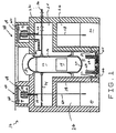
- FIG. 1 is a schematic depiction of a nuclear reactor system 10 in accordance with one embodiment of the present invention.
- Nuclear reactor system 10 includes a cylindrical reactor pressure vessel 12 (RPV) which encloses a reactor core 14.
- RPV 12 includes a cylindrical wall 16 sealed at one end by a bottom head 18 and at the other end by a top head 20.
- RPV 12 is housed in a primary containment vessel 22 (PCV).
- Primary containment vessel 22 includes a drywell 24 and a wetwell 26.
- drywell 24 is a concrete cylinder with a domed top
- wetwell 26 is an annular chamber formed by a wall 28 and primary containment vessel 22.
- a suppression pool of water 30 is located in wetwell 26, and RPV 12 is located in drywell 24.
- Valves 32 are fusible, and remain closed until the temperature in drywell 24 exceeds a predetermined temperature. At the predetermined temperature, valves 32 open to permit water to flow from suppression pool 30 into drywell 24. Additionally, a feedwater line 34 supplies water to RPV 12, and a steam line 36 carries steam away from RPV 12.
- PCCS 38 and 40 include condensers, or heat exchangers, 42 and 44 that condense steam and transfer heat to water in a large condenser pool 46 which is vented to the atmosphere.
- Each condenser 42 and 44 is submerged in a respective compartment of condenser pool 46 located high in the reactor building at approximately the same elevation as the fuel pools. Condenser pool 46 is above and outside of PCV 22.
- Each condenser 42 and 44 is coupled to an upper drum 48 and a lower drum 50.
- Steam enters PCCS 38 and 40 through lines, or flowpaths, 52 and 54 respectively.
- a steam-gas mixture may also enter PCCS 38 through line, or flowpath, 56 from RPV 12.
- the steam is condensed in condensers 42 and 44 and falls to lower drum 50. From lower drum 50, the steam condensate and the noncondensable gases can be drained and vented through lines 58 and 60 having outlets which are submerged in suppression pool 30.
- Condenser pool water can heat up to about 101° C. (214° F.).
- the steam which is formed being nonradioactive and having a slight positive pressure relative to station ambient pressure, is vented from the steam space above each PCCS 38 and 40 to outside the reactor building via discharge vents 62.
- a moisture separator may be installed at the entrance to discharge vents 62 to preclude excessive moisture carryover and loss of condenser pool water.
- Nuclear reactor system 10 also includes a glass matrix slab 64 positioned adjacent the floor 66 of PCV 22 and a plurality of heat tubes 68 at least partially embedded in glass matrix slab 64 and extending into the area 70 under PCV 12.
- Glass matrix slab 64 is fabricated from any suitable glass.
- the glass becomes molten at low temperatures to avoid overheating of PCV 22, and has low viscosity and a high thermal expansion coefficient to create powerful convective mixing currents for rapid dissolution of core 14 debris and the transport of heat. Additionally, the glass should be able to dissolve all of core 14 debris.
- a lead borate glass containing lead oxide and boron oxide is used for glass matrix slab 64.
- the lead borate glass includes at least 2 moles of lead oxide per mole of boron oxide.
- Traditional glasses are oxide mixtures that are capable of dissolving oxides but not metals.
- a sacrificial metal oxide such as lead oxide is included in the glass.
- the lead oxide oxidizes the reactive metals generating metal oxides and lead as a by-product.
- the oxidized products of reactive metals, such as zirconium oxide, can be dissolved into the glass matrix.
- other sacrificial metal oxides may be used besides lead oxide.
- each heat tube 68 includes an evaporator portion 72 and a condenser portion 74.
- Each evaporator portion 72 includes a cylindrical evaporator tube 76 and each condenser portion 74 includes a cylindrical condenser tube 78.
- Header pipes 80 connect a plurality of evaporator tubes 76 to a plurality of condenser tubes 78 so that the evaporator tubes 76 are in flow communication with the condenser tubes 78.
- each evaporator tube 76 is positioned parallel to containment floor 66 and embedded in glass matrix slab 64. One end of each evaporator tube 76 extends through glass matrix slab 64 into drywell area 70 under RPV 12 and couples with a header pipe 80. Also, evaporator tubes 76 can be located at various distances from containment floor 66.
- Evaporator tubes 76 are fabricated from materials that are capable of withstanding high temperatures of approximately 2000°C, for example, tungsten and molybdenum. Condenser tubes 74 are also fabricated from heat resistant materials, but can be fabricated from stainless steel.
- Header pipes 80 extend around the perimeter of area 70 under PCV 12 adjacent to wall 28. In the embodiment illustrated in Figure 3, each header pipe 80 extends partially around the perimeter of area 70 forming an arc.
- a plurality of evaporator tubes 76 extend from a header pipe 80 toward the center of area 70 forming a fan like configuration. Additionally, evaporator tubes 76 extending from header pipe 80 are of varying lengths.
- Figure 3 illustrates an arrangement of alternating long, short, and intermediate length of evaporator tubes 76. In alternate embodiments, other arrangements of varying lengths of evaporator tubes 76 can be used, or all evaporator tubes 76 can be of the same length.
- molten core 14 debris will fall onto glass matrix slab 64.
- Glass matrix slab 64 softens and the uranium and fission products mix with the glass matrix.
- the fusible valves (not shown) open to permit water to flow through vent pipes 32 from suppression pool 30 to partially fill drywell 24 and overlie condenser tubes 74.
- Evaporator tubes 76 embedded in glass matrix 64 transfer heat from glass matrix slab 64 to condenser tubes 74 which then release the heat to the water overlying condenser tubes 76.
- PCCS 38 and 40 removes heat from the interior of containment 22 and releases the heat to the environment outside containment 22. As the temperature inside containment 22 decreases, glass matrix slab 64 re-solidifies, thus maintaining the integrity of the containment boundary.
- the above described heat removal system 82 which includes glass matrix slab 64, heat tubes 68, and PCCS 38 and 40, provides protection for PCV 22 of nuclear reactor 10 from attack by molten core 14 debris in the unlikely event of a severe accident where molten core 14 penetrates lower head 20 of RPV 12.
- Glass matrix slab 64 provides protection to floor 66 of PCV 22 from attack by molten core 14 debris.
- heat tubes 68 and PCCS 38 and 40 further provide protection for PCV 22 by cooling molten core 14 debris to prevent a breach of the containment boundary.
Landscapes
- Physics & Mathematics (AREA)
- Engineering & Computer Science (AREA)
- Plasma & Fusion (AREA)
- General Engineering & Computer Science (AREA)
- High Energy & Nuclear Physics (AREA)
- Structure Of Emergency Protection For Nuclear Reactors (AREA)
Abstract
Description
Claims (13)
- A heat removal system for the under vessel area (70) of a nuclear reactor (10), the nuclear reactor (10) comprising a reaction pressure vessel (12) located in a primary containment (22), the primary containment (22) having a floor (66) and comprising a drywell (24), a suppression pool (30), and a passive containment cooling system (38), said heat removal system comprising:a glass matrix slab (64) positioned adjacent the containment floor (66); anda plurality of heat tubes (68), each said heat tube comprising an evaporator portion (72) and a condenser portion (74), said evaporator portion (72) comprising a cylindrical tube (76), at least a portion of said evaporator tube (76) substantially parallel to the containment floor (66) and embedded in said glass matrix slab (64), one end of said evaporator tube (76) extending through said glass matrix slab (64) and into the area (70) below the reactor pressure vessel (12), said condenser portion (74) comprising a cylindrical tube (78) in flow communications with said evaporator tube (76) and extending away from the containment floor (66) in the area (70) below the reactor pressure vessel (12).
- A heat removal system in accordance with Claim 1 further comprising a plurality of header pipes (80), each said header pipe (80) coupled to and in flow communication with at least one evaporator tube (76) and at least one condenser tube (78).
- A heat removal system in accordance with Claim 2 wherein said plurality of header pipes (80) are located around the perimeter of the containment floor (66).
- A heat removal system in accordance with Claim 3 wherein each said header pipe (80) is configured to extend around a portion of the perimeter of the containment floor (66).
- A heat removal system in accordance with Claim 4 wherein each said header pipe (80) forms an arc of a circle.
- A heat removal system in accordance with Claim 5 wherein said evaporator tubes (76) extend from said header pipes (80) in an inverted fan pattern so that a first end of said evaporator tubes (76) is connected to said header pipes (80) and said second end of said evaporator tubes (76) extend toward a point located in the center of the containment floor (66).
- A heat removal system in accordance with Claim 1 wherein said glass matrix slab (64) comprises a lead borate glass.
- A heat removal system in accordance with Claim 7 wherein said lead borate glass comprises lead oxide and boron oxide.
- A heat removal system in accordance with Claim 8 wherein said lead borate glass comprises at least two moles of lead oxide per mole of boron oxide.
- A heat removal system in accordance with Claim 1 wherein said plurality of evaporator tubes (76) comprise tungsten or molybdenum.
- A heat removal system in accordance with Claim 1 wherein said plurality of condenser tubes (78) comprise stainless steel, tungsten, or molybdenum.
- A heat removal system in accordance with Claim 1 further comprising vent tubes (32) configured to connect the suppression pool (30) with the drywell (24).
- A nuclear reactor system (10) comprising:a primary containment vessel (22), said primary containment vessel (22) having a floor (66) and comprising a drywell (24) and a wetwell (26);a reaction pressure vessel (12) located in said primary containment (22);a passive containment cooling system (38);a suppression pool (30) located in said wetwell (26); anda heat removal system in accordance with any one of claims 1 to 12.
Applications Claiming Priority (2)
| Application Number | Priority Date | Filing Date | Title |
|---|---|---|---|
| US441830 | 1995-05-16 | ||
| US09/441,830 US6353651B1 (en) | 1999-11-17 | 1999-11-17 | Core catcher cooling by heat pipe |
Publications (2)
| Publication Number | Publication Date |
|---|---|
| EP1102281A2 true EP1102281A2 (en) | 2001-05-23 |
| EP1102281A3 EP1102281A3 (en) | 2001-06-27 |
Family
ID=23754476
Family Applications (1)
| Application Number | Title | Priority Date | Filing Date |
|---|---|---|---|
| EP00310014A Withdrawn EP1102281A3 (en) | 1999-11-17 | 2000-11-10 | Core catcher cooling by heat pipe |
Country Status (3)
| Country | Link |
|---|---|
| US (1) | US6353651B1 (en) |
| EP (1) | EP1102281A3 (en) |
| JP (1) | JP2001166081A (en) |
Cited By (2)
| Publication number | Priority date | Publication date | Assignee | Title |
|---|---|---|---|---|
| CN102306507A (en) * | 2011-09-15 | 2012-01-04 | 华北电力大学 | Emergency protection system for preventing reactor pressure vessel from melt through |
| CN105355239A (en) * | 2015-11-05 | 2016-02-24 | 中国核电工程有限公司 | Passive containment cooling system |
Families Citing this family (24)
| Publication number | Priority date | Publication date | Assignee | Title |
|---|---|---|---|---|
| JP4070178B2 (en) * | 1998-11-26 | 2008-04-02 | アレヴァ エンペー ゲゼルシャフト ミット ベシュレンクテル ハフツング | Melt capture and cooling system |
| KR20010060933A (en) * | 1999-12-28 | 2001-07-07 | 이종훈 | An Ex-Vessel Core Melt Retention Device Preventing Molten Core Concrete Interaction |
| JP4127630B2 (en) * | 2002-07-29 | 2008-07-30 | 株式会社東芝 | Primary containment vessel |
| US7558360B1 (en) | 2003-12-31 | 2009-07-07 | General Electric Company | Core catcher cooling |
| KR100597723B1 (en) * | 2004-02-10 | 2006-07-10 | 한국원자력연구소 | Core melt passive cooling and confinement |
| JP4580685B2 (en) * | 2004-05-24 | 2010-11-17 | 株式会社東芝 | Primary containment vessel |
| JP4612558B2 (en) * | 2006-02-22 | 2011-01-12 | 株式会社東芝 | Core catcher and reactor containment |
| WO2007099698A1 (en) * | 2006-02-22 | 2007-09-07 | Kabushiki Kaisha Toshiba | Core catcher and its manufacturing method, and reactor container and its modifying method |
| US9793014B2 (en) * | 2008-05-15 | 2017-10-17 | Terrapower, Llc | Heat pipe fission fuel element |
| US20090285348A1 (en) * | 2008-05-15 | 2009-11-19 | Searete Llc, A Limited Liability Corporation Of The State Of Delaware | Heat pipe fission fuel element |
| US20100040187A1 (en) * | 2008-08-12 | 2010-02-18 | Searete Llc, A Limited Liability Corporation Of The State Of Delaware | Heat pipe nuclear fission deflagration wave reactor cooling |
| US9159459B2 (en) * | 2008-08-12 | 2015-10-13 | Terrapower, Llc | Heat pipe nuclear fission deflagration wave reactor cooling |
| KR101287629B1 (en) * | 2011-08-12 | 2013-07-24 | 주식회사 아앤시티 | Device for nuclear reactor treating a melted fuel rod |
| CN103377720B (en) * | 2012-04-27 | 2016-01-27 | 上海核工程研究设计院 | Out-pile fused mass arresting device after a kind of nuclear power plant accident |
| JP5851357B2 (en) * | 2012-06-29 | 2016-02-03 | 株式会社東芝 | Retainer for core melt |
| JP6080712B2 (en) * | 2013-07-10 | 2017-02-15 | 日立Geニュークリア・エナジー株式会社 | Core melt holding device |
| US9581358B2 (en) | 2013-08-30 | 2017-02-28 | Exxonmobil Upstream Research Company | Multi-phase passive thermal transfer for subsea apparatus |
| US10147506B2 (en) | 2014-04-03 | 2018-12-04 | Bwxt Mpower, Inc. | Conformal core cooling and containment structure |
| JP6320271B2 (en) * | 2014-10-14 | 2018-05-09 | 株式会社東芝 | Core melt holding device and nuclear facility |
| JP6668172B2 (en) * | 2016-06-09 | 2020-03-18 | 株式会社東芝 | Core catcher and boiling water nuclear power plant using the same |
| US11710577B2 (en) | 2019-10-15 | 2023-07-25 | Nuscale Power, Llc | Nuclear reactors having liquid metal alloy fuels and/or moderators |
| KR102950290B1 (en) * | 2019-10-15 | 2026-04-08 | 뉴스케일 파워, 엘엘씨 | Heat pipe networks for heat removal, such as heat removal from a nuclear reactor, and related systems and methods |
| JP7705923B2 (en) | 2020-08-17 | 2025-07-10 | ニュースケール パワー エルエルシー | Thermal power conversion system including heat pipes and photovoltaic cells |
| CN113345609B (en) * | 2021-06-02 | 2022-03-01 | 哈尔滨工程大学 | A pressure vessel external cooling system for a floating nuclear power plant |
Family Cites Families (15)
| Publication number | Priority date | Publication date | Assignee | Title |
|---|---|---|---|---|
| DE1501340B2 (en) * | 1965-04-13 | 1971-04-29 | Allmanna Svenska Elektriska AB, Vasteras (Schweden) | SECURITY CONTAINER FOR NUCLEAR REACTORS |
| US3702802A (en) * | 1971-06-16 | 1972-11-14 | Atomic Energy Commission | Nuclear reactor incorporating means for preventing molten fuel from breaching the containment vessel thereof in the event of a core meltdown |
| US4342621A (en) * | 1977-10-11 | 1982-08-03 | Combustion Engineering, Inc. | Molten core catcher and containment heat removal system |
| FR2435784A1 (en) * | 1978-07-20 | 1980-04-04 | Commissariat Energie Atomique | Water-cooled nuclear reactor - incorporates structure stopping melted materials in case of accidental fusion, comprising lead blocks traversed by tubes |
| JPH02281190A (en) * | 1989-03-27 | 1990-11-16 | General Electric Co <Ge> | Safe cooling system of nuclear reactor storage structure |
| US5080857A (en) * | 1989-09-19 | 1992-01-14 | General Electric Company | Passive lower drywell flooder |
| FR2691572B1 (en) * | 1992-05-21 | 1994-07-08 | Electricite De France | DEVICE FOR RECOVERING A MOLTEN CORE FROM A NUCLEAR REACTOR. |
| US5307390A (en) * | 1992-11-25 | 1994-04-26 | General Electric Company | Corium protection assembly |
| US5301215A (en) * | 1992-11-25 | 1994-04-05 | General Electric Company | Nuclear reactor building |
| JPH06324178A (en) * | 1993-05-14 | 1994-11-25 | Ishikawajima Harima Heavy Ind Co Ltd | Heat removing method for melting debris |
| US5410577A (en) * | 1993-11-04 | 1995-04-25 | Martin Marietta Energy Systems, Inc. | Core-melt source reduction system |
| US5426681A (en) * | 1994-01-04 | 1995-06-20 | General Electric Company | Boiling water reactor with combined active and passive safety systems |
| US5511102A (en) * | 1995-03-15 | 1996-04-23 | General Electric Company | Apparatus for draining lower drywell pool water into suppresion pool in boiling water reactor |
| DE19512286C1 (en) * | 1995-04-05 | 1996-10-17 | Siemens Ag | Arrangement for water displacement |
| US5684848A (en) * | 1996-05-06 | 1997-11-04 | General Electric Company | Nuclear reactor heat pipe |
-
1999
- 1999-11-17 US US09/441,830 patent/US6353651B1/en not_active Expired - Fee Related
-
2000
- 2000-11-10 EP EP00310014A patent/EP1102281A3/en not_active Withdrawn
- 2000-11-16 JP JP2000348885A patent/JP2001166081A/en not_active Withdrawn
Cited By (4)
| Publication number | Priority date | Publication date | Assignee | Title |
|---|---|---|---|---|
| CN102306507A (en) * | 2011-09-15 | 2012-01-04 | 华北电力大学 | Emergency protection system for preventing reactor pressure vessel from melt through |
| CN102306507B (en) * | 2011-09-15 | 2014-04-16 | 华北电力大学 | Emergency protection system for preventing reactor pressure vessel from melt through |
| CN105355239A (en) * | 2015-11-05 | 2016-02-24 | 中国核电工程有限公司 | Passive containment cooling system |
| CN105355239B (en) * | 2015-11-05 | 2019-12-13 | 中国核电工程有限公司 | Passive containment cooling system |
Also Published As
| Publication number | Publication date |
|---|---|
| US6353651B1 (en) | 2002-03-05 |
| EP1102281A3 (en) | 2001-06-27 |
| JP2001166081A (en) | 2001-06-22 |
Similar Documents
| Publication | Publication Date | Title |
|---|---|---|
| US6353651B1 (en) | Core catcher cooling by heat pipe | |
| EP2405444B9 (en) | Nuclear reactor containment vessel and method of cooling the nuclear reactor containment vessel | |
| EP3166114B1 (en) | Passive containment cooling and filtered venting system for a nuclear power plant | |
| US8300759B2 (en) | Decay heat removal system comprising heat pipe heat exchanger | |
| EP0528674B1 (en) | Passive cooling system for liquid metal cooled nuclear reactors with backup coolant flow path | |
| EP0462810B1 (en) | Passive cooling safety system for liquid metal cooled nuclear reactors | |
| US3962032A (en) | Fast nuclear reactor | |
| US5158742A (en) | Reactor steam isolation cooling system | |
| JP4612558B2 (en) | Core catcher and reactor containment | |
| EP1555677B1 (en) | Core catcher cooling | |
| EP3067895B1 (en) | Primary containment vessel | |
| KR20190008123A (en) | Mitigation assembly for nuclear reactor comprising a removable sealing plug | |
| US5889830A (en) | Cooling system for cooling a containment chamber constructed for receiving a core melt | |
| RU2169953C2 (en) | Nuclear-reactor core melt trap | |
| EP0492899A1 (en) | Passive hydraulic vacuum breaker | |
| US5511102A (en) | Apparatus for draining lower drywell pool water into suppresion pool in boiling water reactor | |
| EP0390486A2 (en) | Nuclear reactor containment safety cooling system | |
| US4671922A (en) | Nuclear reactor cooled by a liquid metal | |
| JP4311932B2 (en) | Containment vessel and boiling water reactor having the containment vessel | |
| JP4031259B2 (en) | Reactor containment cooling equipment | |
| JP3666836B2 (en) | Reactor containment cooling equipment | |
| JPS60205278A (en) | Fast breeder reactor | |
| JPS63151894A (en) | Nuclear power plant | |
| JPH06194484A (en) | Cooling facility for PCV | |
| CN113421664A (en) | Lead-based fast reactor passive residual heat removal system based on containment and reactor vessel |
Legal Events
| Date | Code | Title | Description |
|---|---|---|---|
| PUAI | Public reference made under article 153(3) epc to a published international application that has entered the european phase |
Free format text: ORIGINAL CODE: 0009012 |
|
| PUAL | Search report despatched |
Free format text: ORIGINAL CODE: 0009013 |
|
| AK | Designated contracting states |
Kind code of ref document: A2 Designated state(s): CH DE FI LI SE |
|
| AX | Request for extension of the european patent |
Free format text: AL;LT;LV;MK;RO;SI |
|
| AK | Designated contracting states |
Kind code of ref document: A3 Designated state(s): AT BE CH CY DE DK ES FI FR GB GR IE IT LI LU MC NL PT SE TR |
|
| AX | Request for extension of the european patent |
Free format text: AL;LT;LV;MK;RO;SI |
|
| 17P | Request for examination filed |
Effective date: 20011227 |
|
| AKX | Designation fees paid |
Free format text: CH DE FI LI SE |
|
| 17Q | First examination report despatched |
Effective date: 20020527 |
|
| STAA | Information on the status of an ep patent application or granted ep patent |
Free format text: STATUS: THE APPLICATION IS DEEMED TO BE WITHDRAWN |
|
| 18D | Application deemed to be withdrawn |
Effective date: 20030722 |