EP1102263A1 - BCA data replay - Google Patents
BCA data replay Download PDFInfo
- Publication number
- EP1102263A1 EP1102263A1 EP00403146A EP00403146A EP1102263A1 EP 1102263 A1 EP1102263 A1 EP 1102263A1 EP 00403146 A EP00403146 A EP 00403146A EP 00403146 A EP00403146 A EP 00403146A EP 1102263 A1 EP1102263 A1 EP 1102263A1
- Authority
- EP
- European Patent Office
- Prior art keywords
- data
- bca
- reading
- data set
- disk
- Prior art date
- Legal status (The legal status is an assumption and is not a legal conclusion. Google has not performed a legal analysis and makes no representation as to the accuracy of the status listed.)
- Withdrawn
Links
- 238000000034 method Methods 0.000 claims abstract description 31
- 238000010200 validation analysis Methods 0.000 claims abstract description 3
- 230000000977 initiatory effect Effects 0.000 claims description 4
- 239000000872 buffer Substances 0.000 description 20
- 238000005520 cutting process Methods 0.000 description 12
- 230000015654 memory Effects 0.000 description 12
- 101000929942 Megasphaera elsdenii Acyl-CoA dehydrogenase, short-chain specific Proteins 0.000 description 9
- 238000003860 storage Methods 0.000 description 7
- 238000005286 illumination Methods 0.000 description 5
- 238000011084 recovery Methods 0.000 description 5
- 238000010845 search algorithm Methods 0.000 description 4
- 239000000463 material Substances 0.000 description 3
- 230000008569 process Effects 0.000 description 3
- 101150111783 NTRK1 gene Proteins 0.000 description 2
- 230000004913 activation Effects 0.000 description 2
- 239000003990 capacitor Substances 0.000 description 2
- 238000006243 chemical reaction Methods 0.000 description 2
- 230000007812 deficiency Effects 0.000 description 2
- 238000001514 detection method Methods 0.000 description 2
- 238000010586 diagram Methods 0.000 description 2
- 230000006870 function Effects 0.000 description 2
- 238000004519 manufacturing process Methods 0.000 description 2
- 230000004044 response Effects 0.000 description 2
- 238000000926 separation method Methods 0.000 description 2
- 230000005236 sound signal Effects 0.000 description 2
- 230000003321 amplification Effects 0.000 description 1
- 230000008878 coupling Effects 0.000 description 1
- 238000010168 coupling process Methods 0.000 description 1
- 238000005859 coupling reaction Methods 0.000 description 1
- 230000002950 deficient Effects 0.000 description 1
- 238000009826 distribution Methods 0.000 description 1
- 238000007726 management method Methods 0.000 description 1
- 238000003199 nucleic acid amplification method Methods 0.000 description 1
- 230000003287 optical effect Effects 0.000 description 1
- 238000003825 pressing Methods 0.000 description 1
- 230000010076 replication Effects 0.000 description 1
- 230000001960 triggered effect Effects 0.000 description 1
Images


Classifications
-
- G—PHYSICS
- G11—INFORMATION STORAGE
- G11B—INFORMATION STORAGE BASED ON RELATIVE MOVEMENT BETWEEN RECORD CARRIER AND TRANSDUCER
- G11B7/00—Recording or reproducing by optical means, e.g. recording using a thermal beam of optical radiation by modifying optical properties or the physical structure, reproducing using an optical beam at lower power by sensing optical properties; Record carriers therefor
- G11B7/007—Arrangement of the information on the record carrier, e.g. form of tracks, actual track shape, e.g. wobbled, or cross-section, e.g. v-shaped; Sequential information structures, e.g. sectoring or header formats within a track
- G11B7/00736—Auxiliary data, e.g. lead-in, lead-out, Power Calibration Area [PCA], Burst Cutting Area [BCA], control information
-
- G—PHYSICS
- G11—INFORMATION STORAGE
- G11B—INFORMATION STORAGE BASED ON RELATIVE MOVEMENT BETWEEN RECORD CARRIER AND TRANSDUCER
- G11B20/00—Signal processing not specific to the method of recording or reproducing; Circuits therefor
- G11B20/10—Digital recording or reproducing
-
- G—PHYSICS
- G11—INFORMATION STORAGE
- G11B—INFORMATION STORAGE BASED ON RELATIVE MOVEMENT BETWEEN RECORD CARRIER AND TRANSDUCER
- G11B20/00—Signal processing not specific to the method of recording or reproducing; Circuits therefor
- G11B20/10—Digital recording or reproducing
- G11B20/18—Error detection or correction; Testing, e.g. of drop-outs
-
- G—PHYSICS
- G11—INFORMATION STORAGE
- G11B—INFORMATION STORAGE BASED ON RELATIVE MOVEMENT BETWEEN RECORD CARRIER AND TRANSDUCER
- G11B7/00—Recording or reproducing by optical means, e.g. recording using a thermal beam of optical radiation by modifying optical properties or the physical structure, reproducing using an optical beam at lower power by sensing optical properties; Record carriers therefor
- G11B7/004—Recording, reproducing or erasing methods; Read, write or erase circuits therefor
- G11B7/005—Reproducing
- G11B7/0053—Reproducing non-user data, e.g. wobbled address, prepits, BCA
-
- G—PHYSICS
- G11—INFORMATION STORAGE
- G11B—INFORMATION STORAGE BASED ON RELATIVE MOVEMENT BETWEEN RECORD CARRIER AND TRANSDUCER
- G11B7/00—Recording or reproducing by optical means, e.g. recording using a thermal beam of optical radiation by modifying optical properties or the physical structure, reproducing using an optical beam at lower power by sensing optical properties; Record carriers therefor
- G11B7/002—Recording, reproducing or erasing systems characterised by the shape or form of the carrier
- G11B7/0037—Recording, reproducing or erasing systems characterised by the shape or form of the carrier with discs
Definitions
- This invention relates to the reproduction of a digitally encoded signal from a disk medium and in particular to the recovery of data added subsequent to pressing.
- the BCA data can represent from 10 to 188 bytes of data which is modulated by phase encoding prior to over-writing.
- the BCA data comprises a data field, error detection and correction codes and pre and post amble fields.
- the lead-in data area is read and the lead-in data examined to determine the status of bit 16, which if set to 1 indicates the presence of encoded burst cutting area data. If BCA data is indicated, the burst cutting area is read and the data recovered.
- Current BCA data acquisition methods employ a serial process of data acquisition and error correction where erroneous data initiates a request for additional BCA data from the disk. This request usually jumps the transducer to the beginning of the lead in area then back to the nominal center of the burst cutting area in for a second attempt at BCA data recovery. Failure to recover this disk specific data may render further reproduction of the disk impossible. Such BCA data recovery failures may be attributed to poor data signal recovery possibly resulting from dirty BCA data or "cutting" deficiencies, splattered disk material, swarf or inconsistencies of the lowered reflectance stripes representing the BCA data
- a first method for acquiring data from a recording on a disk medium comprises the steps of, successively reading bits defining a data set from different parts of the disk, continuously error correcting the bits to validate at least a part of the data set read from the disk, and, terminating reading upon successful validation of the data set by the error correcting step.
- a second method for acquiring data from a recording on a disk medium comprises the steps of reading a data set beginning from a first position on the data recording, reading the data set from a second position radially spaced in a first direction from the first position absent acquisition of an error free data set from the first position; and, reading the data set from a third position radially spaced in an opposite direction beyond the first position absent acquisition of an error free data set from the second position.
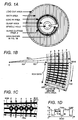
- FIGURE 1A illustrates an exemplary digital versatile disk or DVD with depictions of the positions and distribution of signals written thereon.
- FIGURE 1B depicts in detail, part of the white sector shown in FIGURE 1A.
- FIGURE 1C is a magnified depiction of BCA data records shown in FIGURE 1B.
- FIGURE 1D illustrates a reflected signal and a processed BCA data signal.
- FIGURE 2 is a block diagram of an exemplary digital disk player including inventive arrangements.
- FIGURE 3 is a flow chart illustrating inventive search sequences for data acquisition from BCA data records.
- FIGURE 1A A digital versatile disk or DVD is illustrated in FIGURE 1A which shows the approximate location of various features and data types recorded thereon.
- the disk has a diameter of 120 millimeters with a center spindle hole of 15 millimeters. Adjacent to the spindle hole is a disk clamping area, depicted with dots, having minimum and maximum diameters of 22 and 33 millimeters respectively.
- a guard band is provided between the clamping area and a lead-in data area, depicted with horizontal lines in FIGURE 1A, (multiple dots in FIGURE 1B) and occupying an area between diameters of 45.2 and 48 millimeters.
- the data or "program” area is shown with vertical stripes and is located between diameters of 48 and 116 millimeters, with a lead-out diameter of at least 1 millimeter.
- This optional marking area is known as the burst cutting area or BCA, and is located between diameters of 44.6 to 47 millimeters respectively, (shown in FIGURE 1B between radii R1 and R3 respectively).
- BCA burst cutting area
- Burst cutting area data is phase encoded and written by means of radial cuts or changes to the surface reflectance of the disk and is applied over the existing lead-in data, as depicted by black bars BCAD in FIGURE 1B.
- BCA data is represented by the spacing between the radial cuts BCAD.
- Changes to the surface reflectance in the region of BCA data writing is depicted in FIGURE 1D where BCA data is represented by the low signal areas BCAD and unmodified reflectance area indicated by higher amplitude signal TRKa, for example caused by the reflectance of the track between the BCA cuts.
- Disk lead-in data comprises an initial area with sector addresses from 000000h to 02EEEEh where a data value of 00h is written.
- a reference code is written which is followed by 30 ECC blocks containing a data value 00h.
- control data is written occupying one ECC block (or 16 sectors) which is repeated 192 times.
- At byte position 16 of this control data is a one byte BCA descriptor where a value of all is indicates BCA data presence and a value with 0s indicating a BCA data absence. If the nominal lead-in area dimensional specifications are considered, with a track pitch of 0.74 ⁇ meters, the lead-in data area depicted as LED. may contain approximately 1890 tracks.
- BCA data may overwrite, or stripe, approximately 1620 tracks of lead-in data. Expressed in a different way, there are approximately 1620 transducer locations at which the BCA data record can be read. Thus lead-in data which is not overwritten is present in approximately 270 tracks distributed in areas before and after the BCA data record.
- FIGURE 1C depicts a magnified view of BCA data records BCAD which are written radially across exemplary lead-in data tracks a, b, c, d and e.
- the nominal specified dimensions permit approximately 1620 tracks to be overwritten in burst cutting area Z.
- the transducer is positioned to follow each track, for example track a, or more correctly to remain focused on the single spiral track starting at exemplary radius Ra for acquisition, during several disk revolutions, of multiple data sets from track "a".
- this advantageous method reads BCA data at a plurality different disk radii to advantageously allow data acquisition to be performed independently of the error correction processing.
- the acquisition of multiple BCA data sets at a plurality of disk radii enhances the likelihood of acquiring data capable of successful error correction processing.
- a series of sets of BCA data are acquired and temporarily stored for possible subsequent coupling for error correction if required.
- the advantageous plurality of different radial reading positions for the transducer are depicted by black Xed circles Ra, Rb, Rc, Rd and Re.
- the transducer radial positioning follows a first exemplary sequence which is initiated at read radius Ra which represents the nominal center of the BCA data record.
- the transducer Following acquisition of data from track "a" the transducer is moved, for example by means of the deflection coil 15T to read radius Rb which, for example, is at a radius less than that of radius Ra.
- the selection of transducer position changes or jumps to be radial distances of approximately 100 tracks enables the BCA data search to be performed by use of use of the tracking deflection coil which permitting rapid repositioning.
- the pattern of radial locations Ra, Rb, Rc....Rn, of the transducer is predetermined and derived from a memory, which can be located in either the front end or back end processing.
- the transducer position alternates about the nominal center radius Ra of the data record, with the second read position Rb being nominally 100 tracks less than the nominal center position Ra.
- the third read position Rc is positioned nominally 200 tracks greater than position Rb with the fourth location Rd being nominally 300 tracks less than position Rc.
- the second transducer position Rb is chosen to be closer to the disk spindle hole C, of FIGURE 1B, order that gross miscentering of radius Ra within the BCA record will be quickly identified and the transducer search algorithm adaptively modified to prevent further excursions into areas in which lack BCA data recording.
- the reflected signal from the disk surface is processed, as will be explained with reference to FIGURE 2, to generate a signal which indicates a presence or absence of a BCA data recording reflection. Where an absence of a specific characteristic of the reflected light signal is indicative of transducer positioning over a disk area which does not contain a BCA data record.
- the absence of BCA data signal is used to adapt, modify or select the transducer search algorithm. For example, the progressively increasing, peak to peak search is changed to a unidirectional stepped search sequence.
- the transducer radial position is progressively incremented from a nominal BCA data record start position to acquire a plurality of data.
- the transducer radial positioning is progressively decremented from the nominal end position of BCA data record.
- the advantageous BCA data record search algorithms not only aquires multiple sets of data for error correction, but in addition facilitates a parallel operation which allows separation between BCA data acquisition and BCA data error correction.
- FIGURE 2 is an exemplary block diagram of a digital video disk player.
- Block 10 depicts a deck which may accept a digitally recorded disk 14 for rotation by a motor 12.
- a digital signal is recorded on disk 14 as a spiral track containing pits with lengths determined by an 8/16 modulation coding of a data signal stream.
- the modulation on disk 14 is read by a movable pick up sled 15 which gathers reflected illumination from a laser (not shown).
- the reflected laser light is focused by a lens system on to a photo detector or opto pick-up device, depicted as a diode.
- the pick up sled 15 is positional servo controlled by motor 11 to locate and follow specific tracks on the recorded disk.
- Motor 11 includes a tachometer 11A/B, for example employing an optical or magnetic sensing device 11B which generates a series of pulses per motor revolution.
- pick-up sled 15 may be precisely positioned to access different parts of the recording by, for example, counting tachometer pulses.
- sled 15 may be positioned with reference to a lookup table containing disk sector addresses and corresponding tachometer pulse counts or sled motor activation times at specific motor currents.
- the lens system is positionally controlled by an exemplary magnetic positioner 15T to provide a vernier or precision track following control capability.
- the lens system is focus controlled by an exemplary magnetic positioner 15F.
- Servo controlled motors 11 and 12 are driven by integrated circuit drive amplifier 20.
- the exemplary opto pick-up device of sled 15 is coupled to an opto preamplifier, block 30, which includes drive circuitry for the laser illuminator and a preamplifier which provides amplification and equalization for the reflected signal output from the opto pick-up.
- the amplified and equalized replay signal from opto preamplifier 30 is connected to a channel processor block 40 where the replay signal is employed to synchronize a phase locked loop which is utilized to demodulate the 8:16 modulation employed during recording.
- the channel processor may include further processing of the reflected signal.
- the reflected signal processor processes illumination reflected from the disk surface, for example as depicted in FIGURE 1D, to form a signal having a first state indicative of the presence BCA data reflections and a second state indicative of an absence of BCA data reflections.
- the presence of BCA data in the reflected signal may be identified by processing the signal depicted in FIGURE 1D for example by amplitude clipping between values L and H to produce a cleaned up reflection representative waveform CLREF.
- Waveform CLREF can be processed to determine the presence of BCA data stripes BCAD by for example, detecting the width or time duration of intervals ⁇ 1 and ⁇ 2 depicted in FIGURE 1D.
- a counter may count during interval ⁇ 1 and be reset by waveform part BCAD during interval ⁇ 2, thus, for example, a zero counter output result may be chosen to be indicative of a presence of BCA data reflection.
- waveform part BCAD is absent the counter will not be reset and will eventually over or underflows generating a output indicative of an absence of a BCA data reflection.
- BCA data reflections may be detected by a capacitor charge discharge arrangement where, for example, waveform part TRKa causes a charge to be accumulated at a first rate in, for example a capacitor, with waveform part BCAD causing the charge to be dissipated at a rate greater than the first rate.
- the accumulated charge is measured, for example by a comparator, and if less than a predetermined amount the comparator indicates of a presence of a BCA data reflection signal.
- an absence of a BCA data reflection signal causes charge to accumulate and exceed a second comparator threshold causing the comparator output to indicate an absence of a BCA data reflection signal.
- waveform CLREF may be differentiated and used to trigger a retriggerable monostable multivibrator.
- the occurrence of a pulse due to an edge from waveform part BCAD holds the multivibrator in a re-triggered state which is chosen to be indicative of a reflection from BCA data signal and an absence of a BCA data signal reflection causes retriggering to stop with the multivibrator assuming a stable state indicating an absence of a BCA data signal reflection.
- An MPEG bitstream is encoded for error detection and correction by means of Reed Solomon product coding which is applied to form error correction code (ECC) blocks containing 16 sectors, where each sector contains 2048 bytes of payload data.
- ECC error correction code
- the replay audio and video data stream payloads are de-interleaved or unshuffled and error corrected by means of Reed Solomon product correction within block 40, and implemented in ECC buffer memories (not shown).
- the Reed Solomon error correction circuitry employed for the audio and video data is controllably bypassed and the BCA data is supplied as bit stream 41 to a track buffer memory 60A for storage prior to error correction processing by a central processing unit, element 510 of block 500.
- the error corrected MPEG signal bit stream 41 is coupled to a bit stream or mechanical / track buffer memory 60A.
- the track buffer comprises a DRAM memory type and is used to store an amount of replayed data such that any repositioning of transducer 15 will not result in any visible deficiency when decoded. Thus the final output image stream will appear to be continuous or seamless to the viewer.
- Bitstream buffer memory 60A is part of an exemplary 16 megabit DRAM memory.
- a further exemplary 16 megabit SDRAM memory block is partitioned to provide frame buffers 60C and 60D which provide storage for at least two decoded image frames, compressed video bit stream storage in buffer 60B prior to decoding, an audio bit stream buffer 60E and other storage in buffers 60F, G and H.
- the channel processor 40 also includes timing control circuitry which controls writing to bitstream buffer 60A.
- Data may be intermittently written to the bitstream buffer as a consequence of changes in replay track addresses, for example, resulting from user defined replay video content such as a "Directors cut", parental guidance selection, or even user selectable alternative shot angles.
- disk 14 may be rotated at an increased speed resulting in the transduced bitstream having a higher delivery bit rate.
- the digital video disk player is controlled by a central processing unit or CPU, element 510 of block 500, which accepts the reproduced bitstream and error flags from channel IC 40, and provides control instructions to servo IC 50.
- CPU 510 accepts user control commands from user interface 90, and MPEG decoder control functions from the MPEG decoder element 530 of block 500.
- a system buffer memory 80 is addressed by, and provides data to CPU 510.
- buffer 80 may comprise both RAM and PROM memory locations.
- the RAM may be used to store various data extracted from bitstream 41 by CPU 510, for example such data may include descrambling or decryption information, bitstream and frame buffer memory management data, and navigation data.
- the PROM may, for example contain a plurality of transducer jump algorithms which facilitate both trick modes and BCA data acquisition patterns.
- Microcontroller 510 is coupled the front end via I2C control bus signal 514 to control or request transducer repositioning to acquire the next sector required by a user selected play back sequence.
- the transducer positioning for BCA data acquisition can be controlled by a stored sequence, or sequences. However, upon activation these inventive acquisition sequences automatically search the BCA record until terminated as a consequence of satisfactory error correction of the data or as a result of exceeding a maximum number of transducer search steps.
- the video bit stream is processed by a variable length decoder 531 which searches the bitstream to locate slice and macro-block start codes.
- Certain decoded pictures from each group of pictures are written to frame buffers 60C and 60D for subsequent use as predictors when deriving or constructing other pictures, for example P and B pictures, of a GOP.
- Frame buffers 60C and 60D have a storage capacity of at least two video frames.
- Separated audio packets are stored in audio bit buffer 60E which is read out and coupled for audio decoding in block 110.
- Following MPEG or AC3 audio decoding a digitized audio signal results which is coupled to an audio post processor 130 for digital to analog conversion and generation of various base band audio signal outputs.
- a digital video output signal is transformed into a raster scan format by display buffer 580 from decoded blocks read from reference frame buffer 60C/D.
- the display buffer is coupled to encoder 590 which provides digital to analog signal conversion and generates baseband video components and encoded video signals.
- FIGURE 3 A flow chart is shown in FIGURE 3 which illustrates inventive search methods which employ sequential transducer positioning to explore various parts of a BCA data record.
- a plurality data is acquired at each search position and these data are stored temporarily prior to error correction. These sequential acquisition sequences follow one of a plurality of search sequence until terminated by successful error correction of the BCA data or as a result of exceeding a maximum number of search positions.
- the BCA data acquisition starts with the initiation of a PLAY mode at step 10.
- the transducer or pickup PU is positioned to the disk run in area and the control data indicates the presence of data in the burst cutting area, thus transducer PU is moved, at step 50, to a first data search radius Ra which corresponds to the nominal center of the BCA record as specified in the standards document.
- Transducer PU can be radialy positioned by movement of sled 15, responsive to motor 11 or by means of motor 15T. However, which ever pickup positioning device is employed, it is controlled by stored instructions which can represent tachometer 11A revolutions due to motor 11 or current amplitude supplied to motor 15T.
- the pickup positioning search sequence can be stored in the back end and supplied via bus 514, or may be stored in the front end servo system, for example block 50, to be initiated via bus 514.
- step 75 a test is performed at step 75, to determine if the pickup is receiving illumination reflected from the BCA data record. If step 75 tests NO the pickup may have been mis-positioned and is attempting read a non-BCA recorded area, or alternatively, the BCA record is located in a non-standard position. Thus a NO at step 75 results in the transducer being repositioned at step 80, in a positive radial direction towards the disk outer edge to attempt to locate the BCA record. The distance moved may, for example represent 500 tracks, which is approximately one third of the BCA record length.
- step 95 is depicted as part of the search sequence performed at radius Rc.
- step 75 if the reflectance test is YES fine tracking is performed at step 100 and BCA data is read from the disk at step 200.
- the number of times N the data is read can be determined and controlled by the number of disk revolutions counted or elapsed from the time of positioning at exemplary radius Ra.
- N 2 is required to insure at least one data set is transduced and N values of approximately 10 or more are probably wasteful of acquisition time since "good" recovered data will have achieve an error corrected status and BCA data searching terminated.
- the search sequence automatically repositions the pickup to radius Rb at step 55.
- the pickup is repeatedly repositioned about the nominal record center to search the radial record both outwardly, towards the outer edge and inwardly towards the spindle hole.
- the search sequence repositions the pickup to a lesser radius than that of radius Ra, the nominal center value, by moving the pickup an exemplary 100 tracks closer to the spindle hole.
- This new reading position is tested at step 85 for reflected illumination from the disk. A NO at step 85 indicates that the initial position Ra was not centered in the BCA record and the pickup must be reposition to reacquire BCA data.
- step 55 moved the pickup an exemplary minus 100 tracks relative to radius Ra
- the pickup is now moved or jumped in the reverse direction by twice the step 55 value.
- step 90 the previous jump direction is reversed and the jump size doubled to position the pickup further into the BCA record and away from the record edge detected in step 85.
- the first search embodiment is abandoned and a second search algorithm is adopted which employs a unidirectional sequence of jumps.
- step 85 if the reflectance test is YES, fine tracking is performed at step 150 and BCA data is read from the disk N times at step 250. The number of times the data is controlled by the number of disk revolutions elapsed since radial position Rb was achieved. Having acquired N sets of BCA data the pickup is moved or jumped at step 60 to read radius Rc, which for example is plus 200 tracks relative position Rb. Thus the pickup is jumped over the nominal center position Ra to be located approximately 100 tracks beyond and closer to the disk outer edge.
- Rc radius
- the transducer or pickup automatically performs an ever widening search of the BCA data record. In addition this search sequence is automatically amended to become unidirectional if the data record edge is detected.
- the sequence of operations performed within dotted boxes Ra, Rb and Rc are performed in a serial sequence, with the subsequent functions capable of implementation by a single processing chain as indicated by functional steps 300 and 300a, which are provided by a common element.
- the sets of data read at steps 200 and 250 are coupled for demodulation in respective steps 300 and 300b with the demodulated data coupled for temporary storage at steps 400 and 400b.
- Data sets acquired from pickup position Ra are read from storage at step 450 and are subject to error correction at step 500, for example Reed Soloman controllably implemented by exemplary processor 510 of FIGURE 2.
- the error corrector is tested at step 800 to determine if error correction was successfully accomplished with a YES terminating BCA data acquisition at step 900. If step 800 tested NO, the data was uncorrectable and a counter is decremented at step 810. The counter is set to a value of N-1 where N represents the number of data sets acquired at each read position.
- step 820 The value of counter 810 is tested at step 820 for equality with zero to determine if all data sets at the particular read position have been error corrected. If step 820 tests NO the next BCA data set is read memory in response to step 450. In this way a control loop 501 is established which sequentially presents each data set for error processing.
- Step 820 tests YES, when all data sets at the particular read position, for example Ra have been error processed and found to be uncorrectable, causing step 840 to initiate reading of BCA data sets acquired at exemplary position Rb.
- the YES at step 820 sets or loads the value N-1 at step 810 and increments a counter at step 850.
- control loop 501 sequences through the data stored from transducer position Rb and, for example, none of the data is error correctable which results in step 840 initiating reading of data from t exemplary position Rc.
- the counter at step 850 is incremented and tested at step 855 for equality with a value M which represents the number of jumps performed by the transducer.
- step 855 tests YES indicating that all data sets from all transducer positions have failed error correction. Hence failure to acquire BCA data is indicated at step 860.
- step 855 Unlike current methods which employ a serial process of data acquisition and error correction with erroneous data initiating a request for additional BCA data from the disk.
- FIGURE 3 depicts various advantageous sequences for acquiring BCA data.
- the data record is searched at a plurality disk radii to advantageously searched bi-directionally to maximize the speedy acquisition of error correctable data.
- bi-directional searching is adaptively changed to a unidirectional search when the BCA record edge is detected.
- the BCA data record is systematically and adaptively searched to acquire BCA data independently of the error correction processing.
Landscapes
- Engineering & Computer Science (AREA)
- Signal Processing (AREA)
- Signal Processing For Digital Recording And Reproducing (AREA)
- Optical Recording Or Reproduction (AREA)
Applications Claiming Priority (2)
| Application Number | Priority Date | Filing Date | Title |
|---|---|---|---|
| US09/444,857 US6708299B1 (en) | 1999-11-22 | 1999-11-22 | BCA data replay |
| US444857 | 1999-11-22 |
Publications (1)
| Publication Number | Publication Date |
|---|---|
| EP1102263A1 true EP1102263A1 (en) | 2001-05-23 |
Family
ID=23766639
Family Applications (1)
| Application Number | Title | Priority Date | Filing Date |
|---|---|---|---|
| EP00403146A Withdrawn EP1102263A1 (en) | 1999-11-22 | 2000-11-13 | BCA data replay |
Country Status (8)
| Country | Link |
|---|---|
| US (1) | US6708299B1 (enExample) |
| EP (1) | EP1102263A1 (enExample) |
| JP (2) | JP4917706B2 (enExample) |
| KR (1) | KR100717102B1 (enExample) |
| CN (1) | CN1236425C (enExample) |
| MY (1) | MY138292A (enExample) |
| SG (1) | SG96578A1 (enExample) |
| TW (1) | TW535144B (enExample) |
Cited By (8)
| Publication number | Priority date | Publication date | Assignee | Title |
|---|---|---|---|---|
| WO2003063148A1 (en) * | 2002-01-25 | 2003-07-31 | Sony Corporation | Information recording disc, recording and / or reproducing device and method |
| WO2003069609A3 (en) * | 2002-02-18 | 2003-10-16 | Koninkl Philips Electronics Nv | Optical recording medium and playback method for the same |
| US6708299B1 (en) * | 1999-11-22 | 2004-03-16 | Thomson Licensing S.A. | BCA data replay |
| EP1688932A3 (en) * | 2005-02-02 | 2006-08-16 | Kabushiki Kaisha Toshiba | Optical disk, optical disk drive and method of playing back an optical disk |
| EP1662496A3 (en) * | 2004-11-30 | 2006-12-13 | Kabushiki Kaisha Toshiba | Information storage medium, stamper disc apparatus and management information playback method |
| EP1561207A4 (en) * | 2002-11-04 | 2008-12-10 | Samsung Electronics Co Ltd | OPTICAL DISK HAVING LOCATION POLARITY INFORMATION, AND APPARATUSES AND METHODS OF RECORDING AND REPRODUCING USER DATA ON THIS DISK |
| EP1524652A4 (en) * | 2003-04-14 | 2009-01-14 | Panasonic Corp | OPTICAL RECORDING MEDIUM, OPTICAL RECORDING MEDIUM MANUFACTURING METHOD AND REPRODUCTION METHOD FOR OPTICAL RECORDING MEDIUM |
| AU2003238047B2 (en) * | 2002-01-25 | 2009-06-04 | Koninklijke Philips Electronics N.V. | Information recording device and method, information reproducing device and method, recording medium, program, and disc recording medium |
Families Citing this family (24)
| Publication number | Priority date | Publication date | Assignee | Title |
|---|---|---|---|---|
| EP1385165A3 (en) * | 1999-08-25 | 2009-01-07 | Sony Corporation | Information transmitting device and information transmitting method |
| US6904232B1 (en) * | 2000-04-04 | 2005-06-07 | Zoran Corporation | Method and apparatus for seeking the burst cutting area of DVD media |
| KR100727916B1 (ko) * | 2001-05-02 | 2007-06-13 | 삼성전자주식회사 | 광디스크 |
| TWI233606B (en) * | 2002-05-22 | 2005-06-01 | Sanyo Electric Co | Decode device |
| CA2487406C (en) * | 2003-01-23 | 2012-02-21 | Lg Electronics Inc. | Recording medium with copy protection information formed in intermittent or alternate wobbled pits and apparatus and methods for forming, recording, and reproducing the recording medium |
| KR100932508B1 (ko) * | 2003-01-27 | 2009-12-17 | 엘지전자 주식회사 | 고밀도 광디스크의 디스크 주요 정보 관리방법 |
| JP4468942B2 (ja) * | 2003-01-23 | 2010-05-26 | エルジー エレクトロニクス インコーポレイティド | 選択的情報を有する記録媒体と、その記録媒体にデータを形成し、記録し、再生するための装置及び方法と、再生を制御するための装置及び方法 |
| KR100952949B1 (ko) * | 2003-01-24 | 2010-04-15 | 엘지전자 주식회사 | 고밀도 광디스크의 복사 방지 정보 관리방법 |
| KR20040105963A (ko) * | 2003-06-10 | 2004-12-17 | 삼성전자주식회사 | 광 디스크의 bca에 기록된 정보를 디코딩하는 장치 및방법 |
| JP3906996B2 (ja) | 2003-08-28 | 2007-04-18 | 船井電機株式会社 | Dvd再生装置およびディスク再生装置 |
| JP3972911B2 (ja) * | 2004-02-24 | 2007-09-05 | ソニー株式会社 | データ処理装置および方法、ならびに、再生装置および方法 |
| WO2005122150A1 (ja) | 2004-06-09 | 2005-12-22 | Matsushita Electric Industrial Co., Ltd. | 光ディスク装置および方法 |
| KR100574053B1 (ko) * | 2004-08-17 | 2006-04-27 | 삼성전자주식회사 | 광디스크의 bca 시크시의 편차를 보정하기 위한bca시크편차 보정 방법 |
| CN100411050C (zh) * | 2004-12-06 | 2008-08-13 | 上海乐金广电电子有限公司 | 数据错误修正部及其方法 |
| KR100598279B1 (ko) | 2005-01-05 | 2006-07-07 | 엘지전자 주식회사 | 광디스크 기기에서의 비씨에이 영역 서치장치 및 방법 |
| US20060274617A1 (en) * | 2005-06-03 | 2006-12-07 | Musto James J | Techniques for forming burst cutting area mark |
| US7554889B2 (en) * | 2005-07-28 | 2009-06-30 | Zoran Corporation | Data sampling and extraction method and system |
| US7496009B2 (en) * | 2005-11-24 | 2009-02-24 | Realtek Semiconductor Corp. | Method and apparatus for detecting BCA on an optical disc |
| JP2007323705A (ja) | 2006-05-30 | 2007-12-13 | Toshiba Samsung Storage Technology Corp | 光ディスク装置、およびバーコード読み取り方法 |
| US7659579B2 (en) * | 2006-10-06 | 2010-02-09 | International Business Machines Corporation | FETS with self-aligned bodies and backgate holes |
| JP2010027172A (ja) * | 2008-07-23 | 2010-02-04 | Sony Corp | 情報処理装置および方法、並びにプログラム |
| US8369196B1 (en) | 2010-05-04 | 2013-02-05 | Cinram International Inc. | BCA recording on optical recording medium |
| US8526282B1 (en) | 2010-07-07 | 2013-09-03 | Cinram Group, Inc. | Method for replicating media using unique identifiers |
| US12235475B2 (en) | 2019-02-08 | 2025-02-25 | Avery Dennison Corporation | Flexible retroreflective sheeting |
Citations (7)
| Publication number | Priority date | Publication date | Assignee | Title |
|---|---|---|---|---|
| EP0741382A1 (en) * | 1994-11-17 | 1996-11-06 | Matsushita Electric Industrial Co., Ltd. | Marking generating apparatus, method of forming laser marking on optical disk, reproducing apparatus, optical disk and optical disk producing method |
| JPH10198965A (ja) * | 1997-01-10 | 1998-07-31 | Sony Corp | 光ディスク再生方法及び光ディスク再生装置 |
| JPH10228646A (ja) * | 1997-02-13 | 1998-08-25 | Sony Corp | ディスク再生装置 |
| US5914928A (en) * | 1996-03-25 | 1999-06-22 | Kabushiki Kaisha Toshiba | Information recording disk having replacement area |
| EP0926664A2 (en) * | 1997-12-26 | 1999-06-30 | Kabushiki Kaisha Toshiba | Optical disk and optical disk apparatus |
| GB2332977A (en) * | 1997-12-31 | 1999-07-07 | Samsung Electronics Co Ltd | Optical disk and player and method for identifying disk type |
| JP2000132903A (ja) * | 1998-10-23 | 2000-05-12 | Texas Instr Japan Ltd | データ誤り訂正装置およびその方法 |
Family Cites Families (8)
| Publication number | Priority date | Publication date | Assignee | Title |
|---|---|---|---|---|
| JPH01173271A (ja) * | 1987-12-28 | 1989-07-07 | Hitachi Ltd | マーク読み取り方式 |
| JP2972801B2 (ja) * | 1991-08-08 | 1999-11-08 | オムロン株式会社 | 光学式読取り装置 |
| JPH10233019A (ja) * | 1996-01-22 | 1998-09-02 | Matsushita Electric Ind Co Ltd | 光ディスク、光ディスク製造装置、光ディスク再生装置 |
| US6188538B1 (en) * | 1998-06-19 | 2001-02-13 | Hewlett Packard Company | Retry off-track positioning table |
| JP2000011519A (ja) * | 1998-06-25 | 2000-01-14 | Matsushita Electric Ind Co Ltd | ディスクドライブ装置およびディスク再生方法 |
| KR100362567B1 (ko) * | 1998-12-24 | 2003-04-07 | 삼성전자 주식회사 | 버스트컷팅영역에기록되어있는정보들을디코딩하기위한동기정보검출방법 |
| US6332204B1 (en) * | 1999-03-31 | 2001-12-18 | International Business Machines Corporation | Recovering and relocating unreliable disk sectors when encountering disk drive read errors |
| US6708299B1 (en) * | 1999-11-22 | 2004-03-16 | Thomson Licensing S.A. | BCA data replay |
-
1999
- 1999-11-22 US US09/444,857 patent/US6708299B1/en not_active Expired - Lifetime
-
2000
- 2000-10-19 SG SG200006025A patent/SG96578A1/en unknown
- 2000-11-02 TW TW089123109A patent/TW535144B/zh not_active IP Right Cessation
- 2000-11-13 EP EP00403146A patent/EP1102263A1/en not_active Withdrawn
- 2000-11-17 JP JP2000351167A patent/JP4917706B2/ja not_active Expired - Fee Related
- 2000-11-21 MY MYPI20005440A patent/MY138292A/en unknown
- 2000-11-21 KR KR1020000069171A patent/KR100717102B1/ko not_active Expired - Fee Related
- 2000-11-22 CN CNB001284479A patent/CN1236425C/zh not_active Expired - Fee Related
-
2010
- 2010-04-16 JP JP2010094705A patent/JP2010182413A/ja active Pending
Patent Citations (9)
| Publication number | Priority date | Publication date | Assignee | Title |
|---|---|---|---|---|
| EP0741382A1 (en) * | 1994-11-17 | 1996-11-06 | Matsushita Electric Industrial Co., Ltd. | Marking generating apparatus, method of forming laser marking on optical disk, reproducing apparatus, optical disk and optical disk producing method |
| US5914928A (en) * | 1996-03-25 | 1999-06-22 | Kabushiki Kaisha Toshiba | Information recording disk having replacement area |
| JPH10198965A (ja) * | 1997-01-10 | 1998-07-31 | Sony Corp | 光ディスク再生方法及び光ディスク再生装置 |
| US6034937A (en) * | 1997-01-10 | 2000-03-07 | Sony Corporation | Optical disc reproduction method and optical disc reproduction apparatus |
| JPH10228646A (ja) * | 1997-02-13 | 1998-08-25 | Sony Corp | ディスク再生装置 |
| US6034934A (en) * | 1997-02-13 | 2000-03-07 | Sony Corporation | Disc reproduction apparatus |
| EP0926664A2 (en) * | 1997-12-26 | 1999-06-30 | Kabushiki Kaisha Toshiba | Optical disk and optical disk apparatus |
| GB2332977A (en) * | 1997-12-31 | 1999-07-07 | Samsung Electronics Co Ltd | Optical disk and player and method for identifying disk type |
| JP2000132903A (ja) * | 1998-10-23 | 2000-05-12 | Texas Instr Japan Ltd | データ誤り訂正装置およびその方法 |
Non-Patent Citations (3)
| Title |
|---|
| ANONYMOUS: "DVD - Wikipedia", 30 June 2017 (2017-06-30), XP055387966, Retrieved from the Internet <URL:https://en.wikipedia.org/w/index.php?title=DVD&oldid=788275490> [retrieved on 20170705] * |
| DVD Specification for Read-Only Disc / Part 1, Physical Specifications Version 1, Appendix K * |
| PATENT ABSTRACTS OF JAPAN vol. 2000, no. 08 6 October 2000 (2000-10-06) * |
Cited By (26)
| Publication number | Priority date | Publication date | Assignee | Title |
|---|---|---|---|---|
| US6708299B1 (en) * | 1999-11-22 | 2004-03-16 | Thomson Licensing S.A. | BCA data replay |
| KR100717102B1 (ko) * | 1999-11-22 | 2007-05-11 | 톰슨 라이센싱 | Bca 데이터 재생 방법 |
| US7624331B2 (en) | 2002-01-25 | 2009-11-24 | Sony Corporation | Information recording disc, recording and/or reproducing device and method |
| AU2003238047B2 (en) * | 2002-01-25 | 2009-06-04 | Koninklijke Philips Electronics N.V. | Information recording device and method, information reproducing device and method, recording medium, program, and disc recording medium |
| US7861142B2 (en) | 2002-01-25 | 2010-12-28 | Sony Corporation | Information recording disc, recording and/or reproducing device and method |
| WO2003063148A1 (en) * | 2002-01-25 | 2003-07-31 | Sony Corporation | Information recording disc, recording and / or reproducing device and method |
| US7454688B2 (en) | 2002-01-25 | 2008-11-18 | Sony Corporation | Information recording disc, recording and/or reproducing device and method |
| AU2003238047C1 (en) * | 2002-01-25 | 2009-11-05 | Koninklijke Philips Electronics N.V. | Information recording device and method, information reproducing device and method, recording medium, program, and disc recording medium |
| WO2003069609A3 (en) * | 2002-02-18 | 2003-10-16 | Koninkl Philips Electronics Nv | Optical recording medium and playback method for the same |
| US7616552B2 (en) | 2002-02-18 | 2009-11-10 | Koninklijke Philips Electronics, N.V. | Phase-change optical recording medium having first and second track pitches |
| EP2006847A3 (en) * | 2002-02-18 | 2009-01-14 | Koninklijke Philips Electronics N.V. | Optical recording medium and playback method for the same |
| EP1561207A4 (en) * | 2002-11-04 | 2008-12-10 | Samsung Electronics Co Ltd | OPTICAL DISK HAVING LOCATION POLARITY INFORMATION, AND APPARATUSES AND METHODS OF RECORDING AND REPRODUCING USER DATA ON THIS DISK |
| US8179758B2 (en) | 2002-11-04 | 2012-05-15 | Samsung Electronics Co., Ltd. | Optical disc having tracking polarity information, and apparatuses and methods for recording and reproducing user data on the same |
| US7898917B2 (en) | 2002-11-04 | 2011-03-01 | Samsung Electronics Co., Ltd. | Optical disc having tracking polarity information, and apparatuses and methods for recording and reproducing user data on the same |
| US8116193B2 (en) | 2003-04-14 | 2012-02-14 | Panasonic Corporation | Optical recording medium, manufacturing method for optical recording medium, and reproducing method for optical recording medium |
| EP1524652A4 (en) * | 2003-04-14 | 2009-01-14 | Panasonic Corp | OPTICAL RECORDING MEDIUM, OPTICAL RECORDING MEDIUM MANUFACTURING METHOD AND REPRODUCTION METHOD FOR OPTICAL RECORDING MEDIUM |
| US7948860B2 (en) | 2003-04-14 | 2011-05-24 | Panasonic Corporation | Optical recording medium, manufacturing method for optical recording medium, and reproducing method for optical recording medium |
| EP2146347A1 (en) * | 2003-04-14 | 2010-01-20 | Panasonic Corporation | Manufacturing method for optical recording medium |
| US7808881B2 (en) | 2003-04-14 | 2010-10-05 | Panasonic Corporation | Optical recording medium, optical recording medium manufacturing method, and optical recording medium reproducing method |
| US7821909B2 (en) | 2003-04-14 | 2010-10-26 | Panasonic Corporation | Optical recording medium, manufacturing method for optical recording medium, and reproducing method for optical recording medium |
| EP2244257A3 (en) * | 2003-04-14 | 2010-12-22 | Panasonic Corporation | Optical recording medium |
| EP2242050A3 (en) * | 2003-04-14 | 2010-12-22 | Panasonic Corporation | Optical recording medium |
| EP1662496A3 (en) * | 2004-11-30 | 2006-12-13 | Kabushiki Kaisha Toshiba | Information storage medium, stamper disc apparatus and management information playback method |
| CN100388367C (zh) * | 2005-02-02 | 2008-05-14 | 株式会社东芝 | 光盘、光盘驱动器和播放光盘的方法 |
| US7551533B2 (en) | 2005-02-02 | 2009-06-23 | Kabushiki Kaisha Toshiba | Optical disk, optical disk drive and method of playing back an optical disk |
| EP1688932A3 (en) * | 2005-02-02 | 2006-08-16 | Kabushiki Kaisha Toshiba | Optical disk, optical disk drive and method of playing back an optical disk |
Also Published As
| Publication number | Publication date |
|---|---|
| KR20010051834A (ko) | 2001-06-25 |
| HK1035801A1 (en) | 2001-12-07 |
| MY138292A (en) | 2009-05-29 |
| SG96578A1 (en) | 2003-06-16 |
| JP2001297443A (ja) | 2001-10-26 |
| KR100717102B1 (ko) | 2007-05-11 |
| JP4917706B2 (ja) | 2012-04-18 |
| JP2010182413A (ja) | 2010-08-19 |
| TW535144B (en) | 2003-06-01 |
| US6708299B1 (en) | 2004-03-16 |
| CN1236425C (zh) | 2006-01-11 |
| CN1299132A (zh) | 2001-06-13 |
Similar Documents
| Publication | Publication Date | Title |
|---|---|---|
| US6708299B1 (en) | BCA data replay | |
| US5448545A (en) | System for reproducing digital information in a pulse-length modulation format | |
| CN100520945C (zh) | 记录信息的设备和方法 | |
| CN1112700C (zh) | 视频重放自动控制装置 | |
| US6463209B2 (en) | Controlled data flow | |
| JPH087540A (ja) | 情報の伝送或は記録方法、再生方法、及び再生装置 | |
| KR100616048B1 (ko) | 데이타 재생 장치 및 방법 | |
| US4896025A (en) | Information reproducing apparatus for information recording medium having a plurality of information tracks | |
| US5878184A (en) | Device and method for data playback using interpolation address signal | |
| KR100189534B1 (ko) | 비트 에러레이트를 이용한 디지탈 영상기록 재생장치의 트랙킹 제어회로 및 그 제어방법 | |
| US6377748B1 (en) | Replay bit stream searching | |
| CN1073737C (zh) | 同步检测与保护电路以及其方法 | |
| CA1147858A (en) | System for recording digital information in a pulse-length modulation format | |
| US5592457A (en) | System for recording digital information in a pulse-length modulation format | |
| MXPA00011375A (es) | Reproduccion de datos de area de corte de ráfaga | |
| US6320826B1 (en) | Transducer repositioning | |
| HK1035801B (en) | A method for acquiring data from a recording on a disk medium | |
| US5577015A (en) | System for recording digital information in a pulse-length modulation | |
| JP3110353B2 (ja) | 情報再生方法 | |
| KR100618730B1 (ko) | 광 기록매체 및 간헐영상 녹화방법 | |
| RU2310288C2 (ru) | Способ, устройство и носитель записи для записи последовательности сигналов видеоинформации | |
| JP3495005B2 (ja) | ディスク再生方法、及びディスク再生装置 | |
| JPS5994215A (ja) | デ−タ再生装置 | |
| JP3433691B2 (ja) | 画像信号記録再生装置 | |
| JP2005267758A (ja) | アナログレコード再生装置及び記録装置及び情報再生記録システム |
Legal Events
| Date | Code | Title | Description |
|---|---|---|---|
| PUAI | Public reference made under article 153(3) epc to a published international application that has entered the european phase |
Free format text: ORIGINAL CODE: 0009012 |
|
| AK | Designated contracting states |
Kind code of ref document: A1 Designated state(s): DE FR GB IT |
|
| AX | Request for extension of the european patent |
Free format text: AL;LT;LV;MK;RO;SI |
|
| 17P | Request for examination filed |
Effective date: 20011102 |
|
| AKX | Designation fees paid |
Free format text: DE FR GB IT |
|
| RBV | Designated contracting states (corrected) |
Designated state(s): DE FR GB IT |
|
| 17Q | First examination report despatched |
Effective date: 20040602 |
|
| RAP1 | Party data changed (applicant data changed or rights of an application transferred) |
Owner name: THOMSON LICENSING |
|
| RAP1 | Party data changed (applicant data changed or rights of an application transferred) |
Owner name: THOMSON LICENSING |
|
| RIC1 | Information provided on ipc code assigned before grant |
Ipc: G11B 20/18 20060101ALI20010228BHEP Ipc: G11B 7/00 20060101ALI20010228BHEP Ipc: G11B 20/10 20060101AFI20010228BHEP |
|
| STAA | Information on the status of an ep patent application or granted ep patent |
Free format text: STATUS: THE APPLICATION IS DEEMED TO BE WITHDRAWN |
|
| 18D | Application deemed to be withdrawn |
Effective date: 20181121 |