EP1102260A2 - Data recorder capable to prevent buffer underrun errors - Google Patents
Data recorder capable to prevent buffer underrun errors Download PDFInfo
- Publication number
- EP1102260A2 EP1102260A2 EP00125493A EP00125493A EP1102260A2 EP 1102260 A2 EP1102260 A2 EP 1102260A2 EP 00125493 A EP00125493 A EP 00125493A EP 00125493 A EP00125493 A EP 00125493A EP 1102260 A2 EP1102260 A2 EP 1102260A2
- Authority
- EP
- European Patent Office
- Prior art keywords
- data
- recording
- address
- laser beam
- recording medium
- Prior art date
- Legal status (The legal status is an assumption and is not a legal conclusion. Google has not performed a legal analysis and makes no representation as to the accuracy of the status listed.)
- Withdrawn
Links
- 230000015654 memory Effects 0.000 claims description 100
- 238000001514 detection method Methods 0.000 claims description 19
- 238000000034 method Methods 0.000 claims description 13
- 230000003287 optical effect Effects 0.000 description 100
- 230000005540 biological transmission Effects 0.000 description 9
- 230000010355 oscillation Effects 0.000 description 7
- 239000013078 crystal Substances 0.000 description 5
- 230000007423 decrease Effects 0.000 description 5
- 239000000284 extract Substances 0.000 description 5
- 230000001360 synchronised effect Effects 0.000 description 5
- 238000010586 diagram Methods 0.000 description 4
- 230000006870 function Effects 0.000 description 3
- 230000004044 response Effects 0.000 description 3
- 230000002159 abnormal effect Effects 0.000 description 2
- 230000015572 biosynthetic process Effects 0.000 description 2
- 230000003213 activating effect Effects 0.000 description 1
- 230000008859 change Effects 0.000 description 1
- 230000003111 delayed effect Effects 0.000 description 1
- 230000001678 irradiating effect Effects 0.000 description 1
- 230000005415 magnetization Effects 0.000 description 1
- 239000000155 melt Substances 0.000 description 1
- 230000008569 process Effects 0.000 description 1
- 239000000758 substrate Substances 0.000 description 1
Images

Classifications
-
- G—PHYSICS
- G11—INFORMATION STORAGE
- G11B—INFORMATION STORAGE BASED ON RELATIVE MOVEMENT BETWEEN RECORD CARRIER AND TRANSDUCER
- G11B7/00—Recording or reproducing by optical means, e.g. recording using a thermal beam of optical radiation by modifying optical properties or the physical structure, reproducing using an optical beam at lower power by sensing optical properties; Record carriers therefor
- G11B7/12—Heads, e.g. forming of the optical beam spot or modulation of the optical beam
- G11B7/125—Optical beam sources therefor, e.g. laser control circuitry specially adapted for optical storage devices; Modulators, e.g. means for controlling the size or intensity of optical spots or optical traces
- G11B7/126—Circuits, methods or arrangements for laser control or stabilisation
-
- G—PHYSICS
- G11—INFORMATION STORAGE
- G11B—INFORMATION STORAGE BASED ON RELATIVE MOVEMENT BETWEEN RECORD CARRIER AND TRANSDUCER
- G11B19/00—Driving, starting, stopping record carriers not specifically of filamentary or web form, or of supports therefor; Control thereof; Control of operating function ; Driving both disc and head
- G11B19/02—Control of operating function, e.g. switching from recording to reproducing
- G11B19/04—Arrangements for preventing, inhibiting, or warning against double recording on the same blank or against other recording or reproducing malfunctions
-
- G—PHYSICS
- G11—INFORMATION STORAGE
- G11B—INFORMATION STORAGE BASED ON RELATIVE MOVEMENT BETWEEN RECORD CARRIER AND TRANSDUCER
- G11B20/00—Signal processing not specific to the method of recording or reproducing; Circuits therefor
- G11B20/10—Digital recording or reproducing
-
- G—PHYSICS
- G11—INFORMATION STORAGE
- G11B—INFORMATION STORAGE BASED ON RELATIVE MOVEMENT BETWEEN RECORD CARRIER AND TRANSDUCER
- G11B20/00—Signal processing not specific to the method of recording or reproducing; Circuits therefor
- G11B20/10—Digital recording or reproducing
- G11B20/10527—Audio or video recording; Data buffering arrangements
-
- G—PHYSICS
- G11—INFORMATION STORAGE
- G11B—INFORMATION STORAGE BASED ON RELATIVE MOVEMENT BETWEEN RECORD CARRIER AND TRANSDUCER
- G11B20/00—Signal processing not specific to the method of recording or reproducing; Circuits therefor
- G11B20/10—Digital recording or reproducing
- G11B20/12—Formatting, e.g. arrangement of data block or words on the record carriers
- G11B20/1217—Formatting, e.g. arrangement of data block or words on the record carriers on discs
-
- G—PHYSICS
- G11—INFORMATION STORAGE
- G11B—INFORMATION STORAGE BASED ON RELATIVE MOVEMENT BETWEEN RECORD CARRIER AND TRANSDUCER
- G11B27/00—Editing; Indexing; Addressing; Timing or synchronising; Monitoring; Measuring tape travel
- G11B27/10—Indexing; Addressing; Timing or synchronising; Measuring tape travel
-
- G—PHYSICS
- G11—INFORMATION STORAGE
- G11B—INFORMATION STORAGE BASED ON RELATIVE MOVEMENT BETWEEN RECORD CARRIER AND TRANSDUCER
- G11B27/00—Editing; Indexing; Addressing; Timing or synchronising; Monitoring; Measuring tape travel
- G11B27/36—Monitoring, i.e. supervising the progress of recording or reproducing
-
- G—PHYSICS
- G11—INFORMATION STORAGE
- G11B—INFORMATION STORAGE BASED ON RELATIVE MOVEMENT BETWEEN RECORD CARRIER AND TRANSDUCER
- G11B20/00—Signal processing not specific to the method of recording or reproducing; Circuits therefor
- G11B20/10—Digital recording or reproducing
- G11B20/10527—Audio or video recording; Data buffering arrangements
- G11B2020/1062—Data buffering arrangements, e.g. recording or playback buffers
- G11B2020/10814—Data buffering arrangements, e.g. recording or playback buffers involving specific measures to prevent a buffer underrun
-
- G—PHYSICS
- G11—INFORMATION STORAGE
- G11B—INFORMATION STORAGE BASED ON RELATIVE MOVEMENT BETWEEN RECORD CARRIER AND TRANSDUCER
- G11B2220/00—Record carriers by type
- G11B2220/20—Disc-shaped record carriers
- G11B2220/21—Disc-shaped record carriers characterised in that the disc is of read-only, rewritable, or recordable type
- G11B2220/215—Recordable discs
- G11B2220/216—Rewritable discs
-
- G—PHYSICS
- G11—INFORMATION STORAGE
- G11B—INFORMATION STORAGE BASED ON RELATIVE MOVEMENT BETWEEN RECORD CARRIER AND TRANSDUCER
- G11B2220/00—Record carriers by type
- G11B2220/20—Disc-shaped record carriers
- G11B2220/21—Disc-shaped record carriers characterised in that the disc is of read-only, rewritable, or recordable type
- G11B2220/215—Recordable discs
- G11B2220/218—Write-once discs
-
- G—PHYSICS
- G11—INFORMATION STORAGE
- G11B—INFORMATION STORAGE BASED ON RELATIVE MOVEMENT BETWEEN RECORD CARRIER AND TRANSDUCER
- G11B2220/00—Record carriers by type
- G11B2220/20—Disc-shaped record carriers
- G11B2220/25—Disc-shaped record carriers characterised in that the disc is based on a specific recording technology
- G11B2220/2525—Magneto-optical [MO] discs
- G11B2220/2529—Mini-discs
-
- G—PHYSICS
- G11—INFORMATION STORAGE
- G11B—INFORMATION STORAGE BASED ON RELATIVE MOVEMENT BETWEEN RECORD CARRIER AND TRANSDUCER
- G11B2220/00—Record carriers by type
- G11B2220/20—Disc-shaped record carriers
- G11B2220/25—Disc-shaped record carriers characterised in that the disc is based on a specific recording technology
- G11B2220/2537—Optical discs
- G11B2220/2545—CDs
-
- G—PHYSICS
- G11—INFORMATION STORAGE
- G11B—INFORMATION STORAGE BASED ON RELATIVE MOVEMENT BETWEEN RECORD CARRIER AND TRANSDUCER
- G11B2220/00—Record carriers by type
- G11B2220/60—Solid state media
- G11B2220/65—Solid state media wherein solid state memory is used for storing indexing information or metadata
-
- G—PHYSICS
- G11—INFORMATION STORAGE
- G11B—INFORMATION STORAGE BASED ON RELATIVE MOVEMENT BETWEEN RECORD CARRIER AND TRANSDUCER
- G11B27/00—Editing; Indexing; Addressing; Timing or synchronising; Monitoring; Measuring tape travel
- G11B27/10—Indexing; Addressing; Timing or synchronising; Measuring tape travel
- G11B27/11—Indexing; Addressing; Timing or synchronising; Measuring tape travel by using information not detectable on the record carrier
-
- G—PHYSICS
- G11—INFORMATION STORAGE
- G11B—INFORMATION STORAGE BASED ON RELATIVE MOVEMENT BETWEEN RECORD CARRIER AND TRANSDUCER
- G11B27/00—Editing; Indexing; Addressing; Timing or synchronising; Monitoring; Measuring tape travel
- G11B27/10—Indexing; Addressing; Timing or synchronising; Measuring tape travel
- G11B27/19—Indexing; Addressing; Timing or synchronising; Measuring tape travel by using information detectable on the record carrier
-
- G—PHYSICS
- G11—INFORMATION STORAGE
- G11B—INFORMATION STORAGE BASED ON RELATIVE MOVEMENT BETWEEN RECORD CARRIER AND TRANSDUCER
- G11B27/00—Editing; Indexing; Addressing; Timing or synchronising; Monitoring; Measuring tape travel
- G11B27/10—Indexing; Addressing; Timing or synchronising; Measuring tape travel
- G11B27/19—Indexing; Addressing; Timing or synchronising; Measuring tape travel by using information detectable on the record carrier
- G11B27/28—Indexing; Addressing; Timing or synchronising; Measuring tape travel by using information detectable on the record carrier by using information signals recorded by the same method as the main recording
- G11B27/30—Indexing; Addressing; Timing or synchronising; Measuring tape travel by using information detectable on the record carrier by using information signals recorded by the same method as the main recording on the same track as the main recording
- G11B27/3027—Indexing; Addressing; Timing or synchronising; Measuring tape travel by using information detectable on the record carrier by using information signals recorded by the same method as the main recording on the same track as the main recording used signal is digitally coded
-
- G—PHYSICS
- G11—INFORMATION STORAGE
- G11B—INFORMATION STORAGE BASED ON RELATIVE MOVEMENT BETWEEN RECORD CARRIER AND TRANSDUCER
- G11B27/00—Editing; Indexing; Addressing; Timing or synchronising; Monitoring; Measuring tape travel
- G11B27/10—Indexing; Addressing; Timing or synchronising; Measuring tape travel
- G11B27/19—Indexing; Addressing; Timing or synchronising; Measuring tape travel by using information detectable on the record carrier
- G11B27/28—Indexing; Addressing; Timing or synchronising; Measuring tape travel by using information detectable on the record carrier by using information signals recorded by the same method as the main recording
- G11B27/30—Indexing; Addressing; Timing or synchronising; Measuring tape travel by using information detectable on the record carrier by using information signals recorded by the same method as the main recording on the same track as the main recording
- G11B27/3027—Indexing; Addressing; Timing or synchronising; Measuring tape travel by using information detectable on the record carrier by using information signals recorded by the same method as the main recording on the same track as the main recording used signal is digitally coded
- G11B27/3063—Subcodes
-
- G—PHYSICS
- G11—INFORMATION STORAGE
- G11B—INFORMATION STORAGE BASED ON RELATIVE MOVEMENT BETWEEN RECORD CARRIER AND TRANSDUCER
- G11B7/00—Recording or reproducing by optical means, e.g. recording using a thermal beam of optical radiation by modifying optical properties or the physical structure, reproducing using an optical beam at lower power by sensing optical properties; Record carriers therefor
- G11B7/004—Recording, reproducing or erasing methods; Read, write or erase circuits therefor
- G11B7/0045—Recording
Definitions
- the present invention relates to a data recorder, and more particularly, to a data recorder having a buffer memory for storing data provided from an external device and recording the stored data of the buffer memory on a recording medium.
- An optical disc recorder records data on an optical disc, which serves as a recording medium.
- a CD-DA family compact disc-recordable (CD-R) drive is one type of optical disc recorder that is widely used.
- a CD-R is a so-called write-once optical disc on which data is written only once. The recorded data cannot be physically deleted.
- a laser beam is irradiated against the optical disc from an optical head of the CD-R drive. The heat of the laser beam melts a dye and forms recording pits on a recording layer of the optical disc. Data is recorded on the disc by changing the reflecting rate of the recording layer.
- the optical disc recorder includes a buffer memory and an encoder.
- the buffer memory temporarily stores data provided from an external device, such as a personal computer.
- the encoder reads the data from the buffer memory and encodes the read data to record the data on the optical disc.
- the transmission rate of the recording data output from the encoder is faster than the transmission rate of the data provided to the buffer. This decreases the amount of data stored in the buffer memory. If the decrease continues, the data amount ultimately becomes null and the buffer memory becomes empty. This stops the stream of data to the encoder and causes an interruption in the data recorded on the optical disc. This problem is referred to as buffer underrun.
- the interruption in the data recorded on the optical disc resulting from buffer underrun is referred to as a buffer underrun error.
- Data is recorded on an optical disc using a recording technique that designates the file group recorded on the optical disc (e.g., disc at once, track at once).
- a recording technique that designates the file group recorded on the optical disc (e.g., disc at once, track at once).
- Recent CD-R drives record data at a speed four times or eight times the normal recording speed. Further, recent personal computers have multitasking functions to operate CD-R drives. This has increased the tendency of the occurrence of buffer underrun errors.
- Packet writing is one type of data recording that records data in packet units. Packet writing records data on an optical disc when the data reaches the capacity of the packet. This prevents the occurrence of buffer underrun errors.
- link blocks must be formed to connect packets in packet writing. The link blocks decrease the recording capacity of the optical disc.
- CD-ROM drives that are not capable of handling packet writing. Such CD-ROM drives cannot reproduce data written to optical discs through packet writing. In other words, the CD-ROM compatibility required by the CD-R standard (Orange Book Part II) does not include packet writing. For example, packet writing cannot be applied for a CD-DA player. Thus, a CD-R drive cannot record CD-DA audio data through packet writing. Accordingly, there is a need for preventing buffer underrun errors without employing packet writing.
- a CD-rewritable (CD-RW) drive is another type of optical disc recorder that is widely used.
- a CD-RW drive irradiates a laser beam from an optical head against an optical disc. The heat of the laser beam causes phase changes between amorphic and crystalline to form recording pits on the recording layer of the optical disc. This changes the reflecting rate of the recording layer and records data on the optical disc. Data can be repeatedly rewritten to optical discs used by the CD-RW drive. Accordingly, the optical disc remains usable even if a buffer underrun error occurs. However, when a buffer underrun error occurs, the data file that was being recorded before the occurrence of the buffer underrun error must be recorded again. This wastes the recording performed prior to the occurrence of the buffer underrun error and increases the recording time.
- a magneto-optic disc recorder is another type of known data recorder.
- the magneto-optic disc recorder irradiates a laser beam from an optical head against a magneto-optic disc. This applies residual magnetization to the recording layer of the optical disc and records data on the magneto-optic disc.
- Mini disc (MD) drives are widely used magneto-optic disc recorders. However, MD drives have the same problem as CD-RW drives.
- the present invention provides a data recorder for recording data on a recording medium by emitting a laser beam against the recording medium.
- the data recorder includes an interrupt control circuit for interrupting data recording when a predetermined state is detected. The interruption occurs when the laser beam is generated at a relatively low power level.
- a further aspect of the present invention provides a data recorder for recording data on a recording medium by emitting a laser beam against the recording medium.
- the data recorder includes a buffer memory for temporarily storing data that is to be recorded on the recording medium, an interrupt control circuit for interrupting data recording when a predetermined state is detected, and an address memory connected to the buffer memory.
- the address memory stores at least one of an address of the recording medium and an address of the buffer memory when data recording on the recording medium is interrupted. Each address indicates a location of data when the recording interruption occurred.
- a synchronizing circuit sequentially reads the data recorded on the recording medium prior to the recording interruption and the data stored in the buffer memory prior to the recording interruption while synchronizing the recorded data and the stored data.
- a restart circuit restarts data recording on the recording medium based on the address stored in the address memory.
- the interrupt control circuit interrupts data recording when the laser beam is generated at a relatively low power level.
- Another aspect of the present invention provides a data recorder for recording data on a recording medium by emitting a laser beam against the recording medium.
- the data is formed by a plurality of sectors.
- Each of the sectors includes a synch pattern that has a predetermined number of bits representing a low level.
- the laser beam is generated at a low power level in accordance with the low level of the synch pattern.
- the data recorder includes an interrupt control circuit for continuing recording until an interval between sectors appears when detecting a predetermined state and interrupting the recording operation when the laser beam is generated in accordance with the synch pattern of a sector.
- a further aspect of the present invention provides a data recorder for recording data on a recording medium.
- the recorder includes a buffer memory for temporarily storing data, an encoder connected to the buffer memory to encode the data read from the buffer memory and to generate recording data, and a recording unit connected to the encoder to emit a laser beam against the recording medium in accordance with the recording data and record the recording data on the recording medium.
- An interrupt control circuit is connected to the encoder to detect a predetermined state during data recording. Upon the detection of the predetermined state, the interrupt control circuit controls the encoder so that data recording is interrupted when the laser beam is generated at a relatively low power level.
- Another aspect of the present invention provides a method for recording data on a recording medium by emitting a laser beam against the recording medium.
- the data is formed by a plurality of sectors.
- Each of the sectors includes a synch pattern that has a predetermined number of bits representing a low level.
- the laser beam is generated at a low power level in accordance with the low level of the synch pattern.
- the method includes continuing recording until an interval between sectors appears when a predetermined state is detected, and interrupting the recording operation when the laser beam is generated in accordance with the synch pattern of a sector.
- a further aspect of the present invention provides a method for recording data on a recording medium by emitting a laser beam against the recording medium.
- the method includes temporarily storing data in a buffer memory, recording data read from the buffer memory on the recording medium, interrupting data recording when a predetermined state is detected, and storing in an address memory at least one of an address of the recording medium and an address of the buffer memory when data recording on the recording medium is interrupted. Each address indicates a location of data when the recording interruption occurred.
- the method further includes sequentially reading the data recorded on the recording medium prior to the recording interruption and the data stored in the buffer memory prior to the recording interruption, synchronizing the recorded data and the stored data, and restarting data recording on the recording medium based on the address stored in the address memory.
- the interrupting of the data recording is performed when the laser beam is generated at a relatively low power level.
- a CD-R drive 1 includes a spindle motor 2, a spindle servo circuit 3, an optical head 4, an RF amplifier 5, a head servo circuit 6, a decoder 7, a subcode decoding circuit 8, a wobble decoder 9, an ATIP decoding circuit 10, an external connection terminal 11, an interface 12, a buffer memory 13, an encoder 14, an encoder internal RAM 15, a laser drive circuit 16, a crystal oscillation circuit 18, an access control circuit 19, a buffer underrun determination circuit 20, a recording control circuit 21, and a system control circuit 22.
- the CD-R drive 1 is connected to a personal computer 31 via the external connection terminal 11 to record data, which is provided from the personal computer 31, on an optical disc 32 that complies with the CD-R standards. Further, the CD-R drive 1 provides the personal computer 31 with data reproduced from the optical disc 32.
- the spindle motor 2 rotates the optical disc 32.
- the spindle servo control circuit 3 controls the spindle motor 2 so that the optical disc 32 is rotated using the constant linear velocity (CLV) method in accordance with the rotation control signal generated by the wobble decoder 9.
- CLV constant linear velocity
- the optical head 4 When reading data, the optical head 4 irradiates a relatively weak laser beam against the optical disc and, from the reflected laser beam, generates a RF signal (high frequency signal) in correspondence with the data recorded on the optical disc.
- the optical head 4 When recording data, the optical head 4 irradiates a relatively intense laser beam (several tens of times greater than the data reading laser beam) against the optical beam 32 to form recording pits on the recording layer of the optical disc 32 and change the reflecting rate of the recording layer to record data. In synchronism with the recording of data, the optical head 4 generates the RF signal in correspondence with the recorded data from the reflected laser beam.
- the RF amplifier 5 amplifies the RF signal, which is provided from the optical head 4, and digitizes the amplified RF signal to generate a digital data signal.
- the RF signal of the optical head 4 is fed back to the head servo circuit 6 via the RF amplifier 5.
- the head servo circuit 6 uses the RF signal to perform focusing control, tracking control, and sled feed control. Focusing control focuses the laser beam on the recording layer of the optical disc 32. Tracking control tracks the laser beam along a signal track of the optical disc 32. Sled feed control moves the optical head 4 in the radial direction of the optical disc 32.
- the decoder 7 decodes the digital data provided from the RF amplifier 5. Further, the decoder 7 generates a pit clock from the digital data and separates a subcode from the digital data to generate a subcode synchronizing signal.
- the subcode decoding circuit 8 which is incorporated in the decoder 7, decodes the subcode. Further, the subcode decoding circuit 8 generates subcode Q channel data (hereafter referred to as sub-Q data) from the decoded subcode.
- sub-Q data subcode Q channel data
- the wobble decoder 9 extracts a wobble component of 22.05kHz from a pre-groove signal of the optical disc 32 that is included in the digital data provided from the RF amplifier 5. Then, the wobble decoder generates the rotation control signal of the optical disc 32 from the wobble component.
- the ATIP decoding circuit 10 which is incorporated in the wobble decoder 9, uses the wobble component to decode an absolute time in pre-groove (ATIP) and extract absolute time information, or an ATIP address, from the ATIP.
- the absolute time information indicates addresses of locations in the recording medium.
- the interface 12 controls data transmission between the personal computer 31 and the CD-R drive 1.
- the buffer memory 13 is a ring buffer that includes a synchronous dynamic random access memory (SDRAM), which preferably has a FIFO configuration, and the buffer memory 13 stores data provided from the personal computer 31 via the interface 12. Data stored at one address of the buffer memory 13 corresponds to data recorded at one sector of the optical disc 32.
- SDRAM synchronous dynamic random access memory
- An interrupt/restart circuit 43 of the system control circuit 22 controls the encoder 14.
- the encoder 14 reads the data stored in the buffer memory 13 in sector units and encodes the data into recording data for the optical disc 32.
- the RAM 15, which is incorporated in the encoder 14, stores the necessary data for encoding by the encoder 14 and intermediate operation encoding data.
- the encoder 14 adds a synch byte, a header, CD-ROM data error detection code (EDC), and an error correction code (ECC) to the data.
- EDC CD-ROM data error detection code
- ECM error correction code
- the encoder 14 further performs error correction using a cross interleaved Reed-Solomon code (CIRC), which is a CD error correction code, and eight to fourteen modulation (EFM) on the data.
- CIRC cross interleaved Reed-Solomon code
- EFM eight to fourteen modulation
- the encoder 14 adds a subcode, which includes the sub-Q data, and a synchron
- the interrupt/restart circuit 43 also controls the laser drive circuit 16, which provides a laser drive signal to the laser beam source of the optical head 4.
- the voltage of the drive signal is constant when reproducing data and varied in accordance with the recording data output from the encoder 14 when recording data.
- the recording data output from the encoder 14 is low (L)
- recording pits are not formed on the recording layer of the optical disc 32.
- the drive signal is set so that its voltage is the same as when data is reproduced.
- the recording data is high (H)
- the drive signal is set so that its voltage is several tens of times greater than during data reproduction.
- the crystal oscillation circuit 18 generates an oscillation signal based on the oscillation of a crystal oscillator.
- the access control circuit 19 selectively refers to the subcode address of the absolute time information in the sub-Q data and the ATIP address of the absolute time information in the ATIP to control the recording control circuit 21 and the head servo circuit 6. This controls access to the optical disc 32.
- the data provided to the buffer memory 13 is stored in the buffer memory 13 in a predetermined address order.
- the buffer underrun determination circuit 20 directly or indirectly determines the amount of data stored in the buffer memory 13 from the address at which writing or reading is presently performed. Based on the data amount, the buffer underrun determination circuit 20 determines whether or not the buffer memory 13 is in a state in which buffer underrun may occur.
- the recording control circuit 21 controls the interface 12, the access control circuit 19, and the system control circuit 22.
- the system control circuit 22 includes a system clock generation circuit 41, a signal synchronizing circuit 42, the interrupt/restart circuit 43, a retry determination circuit 44, location detection circuits 45, 46, and address memories 47, 48. These circuits 41-48 are laid out on the same chip of an LSI substrate.
- the system clock generation circuit 41 generates from the oscillation signal of the crystal oscillation circuit 18 a reference clock used when recording data. Further, the generation circuit 41 uses a pit clock extracted by the decoder 7 to generate a reproduction clock used when reproducing data. The generation circuit 41 selects the reference clock or the reproduction clock in accordance with the switching control performed by the signal synchronizing circuit 42. The selected clock is used as a system operational clock of the CD-R drive 1. In accordance with the operational clock, the CD-R drive 1 controls the synchronization of the circuits 7-10, 12-16, and 19-22.
- the signal synchronizing circuit 42 controls the recording control circuit 21 so that the recording data output from the encoder 14 is synchronized with the data recorded on the optical disc 32.
- the sub-Q data of the subcode decoding circuit 8 is associated with the sub-Q data of the encoder 14 after synchronizing the subcode synchronizing signal of the decoder 7 with the subcode synchronizing signal of the encoder 14.
- the signal synchronizing circuit 42 controls the system clock generation circuit 41 so that the reference clock or the reproduction clock is output.
- the recording control circuit 21 controls the interrupt/restart circuit 43.
- the interrupt/restart control circuit 43 controls the encoder 14 and the laser drive circuit 16 and, when the buffer underrun determination circuit determines that the buffer memory 13 has entered a state in which buffer underrun may occur, provides the address memories 47, 48 with a recording interrupt signal.
- the address memory 47 stores the address of the read data in the buffer memory 13 when receiving the recording interrupt signal from the interrupt/restart circuit 43.
- the address memory 48 stores the address of the ATIP decoded by the ATIP decoding circuit 10 when receiving the recording interrupt signal from the interrupt/restart circuit 43.
- the location detection circuit 45 compares the address of the data read from the buffer memory 13 with the address stored in the address memory 47. If the data address and the stored address are the same, the location detection circuit 45 activates the recording restart signal.
- the location detection circuit 46 compares the address of the ATIP decoded by the ATIP decoding circuit 10 with the ATIP address stored in the address memory 48. If the decoded ATIP address and the stored ATIP address are the same, the location detection circuit 46 activates the recording restart signal.
- the retry determination circuit 44 instructs the recording control circuit 21 to restart the recording operation of the interface 12, the access control circuit 19, and the system control circuit 22 when the restart signals of the location detection circuits 45, 46 are simultaneously activated.
- the retry determination circuit 44 instructs the control circuit 21 to repeatedly perform data reproduction in the recording restart mode until the two restart signals are synchronously activated.
- the personal computer 31 When a user manipulates the personal computer 31 to record data, the personal computer 31 generates a command accordingly. The command is transferred to the recording control circuit 21 via the interface 12. In response to the command, the recording control circuit 21 controls the interface 12, the access control circuit 19, and the system control circuit 22 to record data.
- the signal synchronizing circuit 42 switches the operational clock output of the system clock generation circuit 41 to the reference clock.
- the circuits 7-10, 12-16, 19-22 of the CD-R drive 1 are synchronized with the operational clock, or the reference clock.
- the data provided from the personal computer 31 is stored in the buffer memory via the interface 12 and read from the buffer memory 13 in sector units.
- the encoder 14 encodes the data read from the buffer memory 13 in sector units to generate recording data.
- the laser drive circuit 16 provides the optical head 4 with drive signal having a voltage corresponding to the recording data. In accordance with the drive signal, the optical head 4 changes the intensity of the laser beam irradiated against the optical disc 32. This forms recording pits on the recording layer of the optical disc 32 and records data on the optical disc 32. Simultaneously, from the laser beam reflected by the optical disc 32, the optical head 4 reproduces the data recorded on the optical disc 32 as the RF signal.
- the RF amplifier 5 amplifies the RF signal provided from the optical head 4 to generate digital data.
- the wobble decoder 9 extracts the wobble component from the digital data and uses the wobble component to generate the rotation control signal.
- the spindle servo circuit 3 controls the spindle motor 2 so that the optical disc 32 is rotated at a constant linear velocity.
- the ATIP decoding circuit 10 decodes the ATIP using the wobble component and extracts the ATIP address of the absolute time information in the ATIP.
- the transmission rate of the data provided from the personal computer 31 is slower than the transmission rate of the data recorded in the optical disc 32 (write speed), that is, when the transmission rate of the data provided to the buffer 13 is slower than that of the data output from the encoder 14, the amount of data stored in the buffer memory 13 decreases.
- the recording control circuit 21 controls the interrupt/restart circuit 43 so that, before the occurrence of a buffer underrun in the buffer memory 13, the address memories 47, 48 are accordingly provided with the interrupt signal and the output of recording data from the encoder 14 is interrupted.
- the interrupt/restart circuit 43 outputs the interrupt signal and stops the output of the recording data from the encoder 14.
- the address memories 47, 48 store the data address of the buffer memory 13.
- the address memory 47 stores the buffer memory address of the data read from the buffer memory 13 when receiving the interrupt signal.
- the address memory 48 stores the ATIP address of the ATIP decoding circuit 10 when receiving the interrupt signal.
- the interrupt/restart circuit 43 When the interrupt/restart circuit 43 outputs the interrupt signal, the sector of the data being output from the encoder 14 is recorded on the optical disc 32.
- the interrupt signal of the interrupt/restart circuit 43 may be output at times between sectors of the recording data.
- the data provided from the personal computer 31 is stored in the buffer memory 13 via the interface 12. As the amount of data stored in the buffer memory 13 increases, the state in which a buffer underrun may occur no longer exists.
- the recording control circuit 21 controls the access control circuit 19 and the system control circuit 22 to perform data reproduction in the recording restart mode.
- the access control circuit 19 controls the head servo circuit 6.
- the head servo circuit 6 controls focusing, tracking, and sled feed of the optical head 4 to move the optical head 4 to a sector location that is prior by a predetermined number of sectors from the sector at which the recording interruption occurred.
- the optical head 4 then irradiates the laser beam from that sector location.
- the interrupt/restart circuit 43 controls the laser drive circuit 16 so that a drive signal having a constant voltage is output from the laser drive circuit 16. This results in the optical head 4 irradiating the optical disc 32 with a relatively weak laser beam. The reflected laser beam reproduces the data recorded on the optical disc prior to the recording interruption, and the optical head 4 outputs the RF signal.
- the RF signal is amplified by the RF amplifier 5 and converted to digital data.
- the decoder 7 decodes the digital data, extracts a pit clock from the digital data, and separates a subcode from the digital data. A subcode synchronizing signal is generated from the subcode.
- the subcode is decoded by the subcode decoding circuit 8 to generate the sub-Q data.
- the signal synchronizing circuit 42 switches the operational clock from the reference clock of the crystal oscillation circuit 18 to the reproduction clock of the decoder 7.
- the circuits 7-10, 12-16, 19-22 of the CD-R drive 1 are operated in accordance with the reproduction clock. By using the reproduction clock, the data recorded on the optical disc 32 prior to the recording interruption is accurately reproduced.
- the recording control circuit 21 controls the interrupt/restart circuit 43 to instruct the encoder 14 to restart the output of the recording data.
- the encoder 14 goes back by a predetermined number of sectors from the data address of the buffer memory 13 at which the recording interruption occurred and starts reading data in sector units from that sector of the buffer memory 13.
- the encoder 14 adds a synch byte, a header, an EDC, and an ECC to the read data, performs the CIRC and EFM processes, and adds a subcode, which includes the sub-Q data, and the subcode synchronizing signal to the read data.
- the drive signal of the laser drive circuit 16 is constant during data reproduction in the recording restart mode. In other words, the drive signal of the laser drive circuit 16 has a low voltage. Accordingly, laser irradiation does not affect the data recorded on the optical disc prior to the interruption.
- the signal synchronizing circuit 42 controls the access control circuit 19 via the recording control circuit 21 and synchronizes the data recorded on the optical disc 32 with the recording data output from the encoder 14.
- the signal synchronizing circuit 42 controls the recording control circuit 21 and the access control circuit 19 so that the subcode synchronizing signal of the decoder 7 is synchronized with the subcode synchronizing signal of the encoder 14 and the sub-Q data of the subcode decoding circuit 8 is associated with the sub-Q data of the encoder 14.
- the location detection circuit 45 compares the address of the data read from the buffer memory 13 with the address stored in the address memory 47 and activates the restart signal when the data address and the stored address are the same.
- the address stored in the address memory 47 is the address of the data read from the buffer memory 13 when the recording of data is interrupted.
- the location detection circuit 46 compares the ATIP address of the ATIP decoding circuit 10 with the ATIP address stored in the address memory 48 and activates the restart signal when the ATIP address and the stored address are the same.
- the ATIP address stored in the address memory 48 is the ATIP address decoded by the ATIP decoding circuit 10 when the recording of data is interrupted.
- the retry determination circuit controls the interface 12, the access control circuit 19, and the system control circuit 22 via the recording control circuit 21.
- the signal synchronizing circuit 42 switches the operational clock of the system clock generation circuit 41 from the reproduction clock to the reference clock when recording is restarted.
- the address of the data read from the buffer memory 13 shifts to the address next to the address at which data recording was interrupted. Further, the address memory 48 and the location detection circuit 46 shift the sector location of the optical disc 32 irradiated by the laser beam to the sector location next to the sector location at which data recording was interrupted. In this state, the signal synchronizing circuit 42 synchronizes the recording data output from the encoder 14 with the data recorded on the optical disc 32. Accordingly, the data of the sector next to the sector at which data recording was interrupted is recorded upon the restart of the recording. In other words, sectors of data are recorded without any interruptions when restarting recording. This ensures the continuity of the recorded data while preventing the occurrence of a buffer underrun error.
- the interrupt/restart circuit 43 outputs the interrupt signal and stops the output of the recording data from the encoder 14.
- the recording data output from the encoder 14 is low, and the laser drive circuit 16 outputs a drive signal, the level of which is the same as that when data is reproduced.
- the power of the laser beam emitted from the optical head 4 is relatively low. That is, the laser beam power of the optical head 4 is low when restarting the recording operation at the same data recording location. Therefore, data that has already been recorded is not damaged even if the recording restart location is offset from where it should be. Further, since the laser beam is not emitted against the recording section corresponding to the low level data, the diameters of pits do not become non-uniform.
- the drive signal output by the laser drive circuit 16 would have a voltage level that is several tens of times greater than when data is reproduced.
- the power of the laser beam output from the optical head 4 would be several tens of times greater than that during the data reproduction operation.
- the recording operation is interrupted at a time at which the level of the recording data output from the encoder 14 goes low.
- the power of the laser beam output from the optical head 4 is low when the recording operation is restarted.
- the optimal time for interrupting the writing of data is at the output of synch pattern data allocated to the head of each sector.
- a synch pattern has 24 bits and includes 11 high bits and 11 low bits.
- the head of each sector includes a period of 11 consecutive low bits, which is the longest low period in the CD standards.
- An address is designated for each sector.
- the address memories 47, 48 hold address data corresponding to sector addresses. Accordingly, the optimal time for interrupting data writing would be during the synch pattern of a sector.
- the buffer underrun determination circuit 20 determine that there is a possibility of a buffer underrun occurring when at least one sector of data is still in the buffer memory 13.
- the retry determination circuit 44 When the two restart signals of the location detection circuits 45, 46 are not synchronously activated (when the two restart signals are activated at different times), the retry determination circuit 44 repeatedly perform data reproduction in the recording restart mode until the two restart signals are synchronously activated. In other words, if an external disturbance occurs for one reason or another (e.g., the application of an external impact to the CD-R drive), the elements 2-22 of the CD-R drive 1 may function erroneously such that the two restart signals are not synchronously activated. Thus, the retry determination circuit 44 repeats data reproduction to avoid the influence of an external disturbance. If the restart signals of the position detection circuits 45, 46 are simultaneously activated, the retry determination circuit 44, the position detection circuit 45, and the address memory 47 may be deleted.
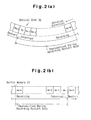
- Fig. 2(a) is a schematic view showing a sector of the optical disc 32.
- Fig. 2(b) is a diagram illustrating the addresses of the buffer memory 13.
- Sectors Sn+1, Sn, Sn-1, Sn-2, whil, Sn-m shown in Fig. 2(a) are respectively associated with addresses An+1, An, An-1, An-2, whil, An-m shown in Fig. 2(b).
- address An is stored in the address memory 47, and the address of the ATIP decoded from the data recorded at sector Sn is stored in the address memory 48.
- the buffer underrun determination circuit 20 determines that a buffer underrun is no longer likely to occur, data reproduction in the recording restart mode is commenced from sector Sn-m by going back from sector Sn, at which recording was interrupted, by a predetermined number of sectors (in this case, m sectors).
- the signal synchronizing circuit 42 synchronizes the recording data output from the encoder 14 with the data recorded on the sectors Sn-m to Sn of the optical disc 32. Then, when the address of the data read from the buffer memory 13 matches the address An stored in the address memory 47, the restart signal of the location detection circuit 45 is activated. When the address of the ATIP decoded by the ATIP decoding circuit 10 matches the ATIP address of the sector Sn stored in the address memory 48, the restart signal of the location detection circuit 46 is activated. When the two restart signals of the location detection circuits 45, 46 are simultaneously activated, the retry determination circuit 44 restarts the recording of data from sector Sn+1, which is next to the sector Sn at which data recording was interrupted.
- the predetermined sector number (m sectors) be sufficient for obtaining time period T1, which is required for the spindle serve circuit 3 to control the spindle motor 2 and the head servo circuit 6 to control the optical head 4, and time period T2, which is required for synchronization by the signal synchronizing circuit 42.
- m is set at 10 to 30.
- the time periods T1, T2 increase as the recording speed of the CD-R drive 1 becomes higher, for example, as the recording speed increases from 4x to 8x. Accordingly, it is preferred that the predetermined sector number be increased as the recording speed increases.
- the recording operation is interrupted when the power level of the laser beam becomes low or during the period when the power of the emitted laser beam is low. This prevents the formation of non-uniform recording pits at the recording restart location. Thus, abnormal recording pits are not formed due to the rewriting of data.
- the recording operation is interrupted when the power level of the laser beam is low and the synch pattern data of the 11 consecutive, low level bits is output. Further, the address of the sector at which the recording interruption occurred is stored in the address memories. Accordingly, the synch pattern and the sector address facilitates the restart of data recording.
Landscapes
- Engineering & Computer Science (AREA)
- Signal Processing (AREA)
- Physics & Mathematics (AREA)
- Optics & Photonics (AREA)
- Multimedia (AREA)
- Optical Recording Or Reproduction (AREA)
- Signal Processing For Digital Recording And Reproducing (AREA)
Abstract
Description
Claims (12)
- A data recorder for recording data on a recording medium by emitting a laser beam against the recording medium, the data recorder characterized by
an interrupt control circuit (43) for interrupting data recording when a predetermined state is detected, wherein the interruption occurs when the laser beam is generated at a relatively low power level. - The data recorder according to claim 1 characterized in that the data includes synch pattern data, and the interrupt control circuit interrupts data recording when the laser beam is generated at the relatively low power level in accordance with the synch pattern data.
- A data recorder for recording data on a recording medium by emitting a laser beam against the recording medium, the data recorder including a buffer memory (13) for temporarily storing data that is to be recorded on the recording medium, the data recorder characterized byan interrupt control circuit (43) for interrupting data recording when a predetermined state is detected;an address memory (47) connected to the buffer memory, wherein the address memory stores at least one of an address of the recording medium and an address of the buffer memory when data recording on the recording medium is interrupted, each address indicating a location of data when the recording interruption occurred;a synchronizing circuit (42) for sequentially reading the data recorded on the recording medium prior to the recording interruption and the data stored in the buffer memory prior to the recording interruption and synchronizing the recorded data and the stored data; anda restart circuit (43) for restarting data recording on the recording medium based on the address stored in the address memory, wherein the interrupt control circuit interrupts data recording when the laser beam is generated at a relatively low power level.
- The data recorder according to claim 3 characterized in that the data includes synch pattern data, and the interrupt control circuit interrupts data recording when the laser beam is generated at the relatively low power level in accordance with the synch pattern data.
- The data recorder according to claim 3 or 4 characterized in that the data is recorded in the recording medium in sector units, each sector including sector address data, and wherein the address memory stores the sector address data where the recording interruption occurred.
- The data recorder according to any one of claims 3 to 5 characterized in that the predetermined state is a state in which there is a possibility that the amount of data in the buffer memory may become null and cause the buffer memory to become empty.
- A data recorder for recording data on a recording medium by emitting a laser beam against the recording medium, wherein the data is formed by a plurality of sectors, each of the sectors including a synch pattern that has a predetermined number of bits representing a low level, wherein the laser beam is generated at a low power level in accordance with the low level of the synch pattern, the data recorder characterized by
an interrupt control circuit (43) for continuing recording until an interval between sectors appears when detecting a predetermined state and interrupting the recording operation when the laser beam is generated in accordance with the synch pattern of a sector. - A data recorder for recording data on a recording medium, the recorder including a buffer memory (13)for temporarily storing data and an encoder (14) connected to the buffer memory to encode the data read from the buffer memory and to generate recording data, and a recording unit (4, 16) connected to the encoder to emit a laser beam against the recording medium in accordance with the recording data and record the recording data on the recording medium, the data recorder characterized by
an interrupt control circuit (43) connected to the encoder to detect a predetermined state during data recording, wherein, upon the detection of the predetermined state, the interrupt control circuit controls the encoder so that data recording is interrupted when the laser beam is generated at a relatively low power level. - The data recorder according to claim 8 characterized in that the data includes synch pattern data, and the interrupt control circuit interrupts data recording when the laser beam is generated in accordance with the synch pattern data.
- The data recorder according to claim 8 or 9 characterized in that the predetermined state is a state in which there is a possibility that the amount of data in the buffer memory may become null and cause the buffer memory to become empty.
- A method for recording data on a recording medium by emitting a laser beam against the recording medium, wherein the data is formed by a plurality of sectors, each of the sectors including a synch pattern that has a predetermined number of bits representing a low level, wherein the laser beam is generated at a low power level in accordance with the low level of the synch pattern, the method characterized bycontinuing recording until an interval between sectors appears when a predetermined state is detected; andinterrupting the recording operation when the laser beam is generated in accordance with the synch pattern of a sector.
- A method for recording data on a recording medium by emitting a laser beam against the recording medium, wherein data is temporarily stored in a buffer memory (13) and data read from the buffer memory is recorded on the recording medium, the method characterized byinterrupting data recording when a predetermined state is detected;storing in an address memory at least one of an address of the recording medium and an address of the buffer memory when data recording on the recording medium is interrupted, each address indicating a location of data when the recording interruption occurred;sequentially reading the data recorded on the recording medium prior to the recording interruption and the data stored in the buffer memory prior to the recording interruption;synchronizing the recorded data and the stored data; andrestarting data recording on the recording medium based on the address stored in the address memory, wherein the interrupting of the data recording is performed when the laser beam is generated at a relatively low power level.
Applications Claiming Priority (4)
| Application Number | Priority Date | Filing Date | Title |
|---|---|---|---|
| JP33141999 | 1999-11-22 | ||
| JP33141999 | 1999-11-22 | ||
| JP2000322549 | 2000-10-23 | ||
| JP2000322549A JP2001216646A (en) | 1999-11-22 | 2000-10-23 | Data recording device |
Publications (2)
| Publication Number | Publication Date |
|---|---|
| EP1102260A2 true EP1102260A2 (en) | 2001-05-23 |
| EP1102260A3 EP1102260A3 (en) | 2006-11-15 |
Family
ID=26573854
Family Applications (1)
| Application Number | Title | Priority Date | Filing Date |
|---|---|---|---|
| EP00125493A Withdrawn EP1102260A3 (en) | 1999-11-22 | 2000-11-21 | Data recorder capable to prevent buffer underrun errors |
Country Status (5)
| Country | Link |
|---|---|
| US (1) | US7167427B1 (en) |
| EP (1) | EP1102260A3 (en) |
| JP (1) | JP2001216646A (en) |
| KR (1) | KR100404402B1 (en) |
| TW (1) | TW479230B (en) |
Families Citing this family (1)
| Publication number | Priority date | Publication date | Assignee | Title |
|---|---|---|---|---|
| KR100727877B1 (en) * | 2005-10-01 | 2007-06-14 | 삼성전자주식회사 | Re-recording method of optical recording and reproducing apparatus |
Family Cites Families (62)
| Publication number | Priority date | Publication date | Assignee | Title |
|---|---|---|---|---|
| US4546462A (en) | 1981-12-04 | 1985-10-08 | Matsushita Electric Industrial Co., Ltd. | Optical data recording and reproducing apparatus |
| DE3275960D1 (en) | 1982-01-06 | 1987-05-07 | Hitachi Ltd | Control circuit for controlling light source in optical disc device |
| DE3546599C2 (en) | 1984-11-20 | 1993-06-03 | Olympus Optical Co., Ltd., Tokio/Tokyo, Jp | |
| JPS61139984A (en) * | 1984-12-11 | 1986-06-27 | Nippon Columbia Co Ltd | Optical disk device |
| US5010534A (en) * | 1984-12-29 | 1991-04-23 | Canon Kabushiki Kaisha | Optical information recording-reproducing apparatus |
| JPS6267731A (en) | 1985-09-20 | 1987-03-27 | Fujitsu Ltd | Method and device for optical recording and reproduction |
| DE3777461D1 (en) | 1986-06-20 | 1992-04-23 | Matsushita Electric Industrial Co Ltd | OPTICAL RECORDING AND PLAYBACK DEVICE. |
| JPH0731904B2 (en) | 1986-08-21 | 1995-04-10 | 株式会社東芝 | Disk recording / reproducing device |
| JPS6361423A (en) * | 1986-09-01 | 1988-03-17 | Seiko Epson Corp | Optical disk device |
| KR910005644B1 (en) | 1986-09-19 | 1991-08-01 | 가부시키가이샤 도시바 | Disk recording/reproducing apparatus |
| JPH06101121B2 (en) | 1988-06-10 | 1994-12-12 | 日本コロムビア株式会社 | Optical disc device and optical disc |
| JP2654122B2 (en) | 1988-09-30 | 1997-09-17 | 株式会社東芝 | Information reproducing apparatus and information recording / reproducing apparatus |
| JPH02223066A (en) | 1989-02-23 | 1990-09-05 | Omron Tateisi Electron Co | Optical recording and reproducing device |
| EP0395115B1 (en) | 1989-04-28 | 1995-06-28 | Kabushiki Kaisha Toshiba | Information recording system |
| JPH0330130A (en) | 1989-06-28 | 1991-02-08 | Sharp Corp | Semiconductor laser drive circuit |
| US5212678A (en) | 1989-11-23 | 1993-05-18 | U.S. Philips Corporation | System for recording and reading information on a record carrier at a constant scanning speed independent of the bit rate of such information |
| JP2588291B2 (en) | 1990-01-31 | 1997-03-05 | 株式会社ケンウッド | Optical disc splicing recording method |
| DE69113357T2 (en) | 1990-07-30 | 1996-05-30 | Nippon Electric Co | Plate control with format control unit, which directly enables a return operation. |
| JP2995822B2 (en) | 1990-08-23 | 1999-12-27 | ソニー株式会社 | Recording device and reproducing device for disk-shaped recording medium |
| JP2703417B2 (en) | 1991-04-05 | 1998-01-26 | 富士通株式会社 | Receive buffer |
| US6438083B1 (en) | 1991-11-19 | 2002-08-20 | Koninklijke Philips Electronics N.V. | Apparatus for recording a continuous information stream in available gaps between pre-recorded portions of a recording track, record carrier so recorded, and apparatus for reading such record carrier |
| NL9102190A (en) | 1991-12-30 | 1993-07-16 | Philips Nv | OPTICAL READING DEVICE AND OPTICAL RECORDING DEVICE. |
| US5333138A (en) * | 1992-03-11 | 1994-07-26 | Ministor Peripherals International Limited | Apparatus and method for preventing data corruption in disk drives from mechanical shock during write operations |
| JP2713681B2 (en) | 1992-03-31 | 1998-02-16 | 太陽誘電株式会社 | Optical disc information recording method and apparatus |
| DE4313177C2 (en) | 1992-04-20 | 2002-04-04 | Mitsubishi Electric Corp | Information reproducing apparatus |
| JP3435703B2 (en) * | 1992-05-20 | 2003-08-11 | ソニー株式会社 | Playback device and playback method |
| JP3393345B2 (en) | 1992-10-31 | 2003-04-07 | ソニー株式会社 | Disk playback device, memory control circuit, and memory control method |
| JP3243883B2 (en) | 1993-04-12 | 2002-01-07 | ソニー株式会社 | Recording or playback device |
| JPH06325476A (en) | 1993-05-14 | 1994-11-25 | Sony Corp | Disk device |
| JPH0778412A (en) | 1993-07-13 | 1995-03-20 | Sony Corp | Recording / reproducing apparatus and method, and reproducing apparatus and method |
| WO1995010111A1 (en) | 1993-10-06 | 1995-04-13 | Nikon Corporation | Optical disk recording device |
| JP2760287B2 (en) | 1994-07-01 | 1998-05-28 | ヤマハ株式会社 | Disk recording and playback device |
| JP2842262B2 (en) | 1994-11-25 | 1998-12-24 | ヤマハ株式会社 | Optical disk recording device |
| DE4445013A1 (en) | 1994-12-16 | 1996-06-20 | Thomson Brandt Gmbh | Vibration-resistant player with improved synchronization |
| TW279228B (en) | 1994-12-16 | 1996-06-21 | Detutsche Thomson Brandt Gmbh | |
| JP3541484B2 (en) | 1995-02-13 | 2004-07-14 | ソニー株式会社 | Playback device, recording device |
| US5818801A (en) | 1995-06-30 | 1998-10-06 | Sanyo Electric Co., Ltd. | Shockproof optical reproduction device |
| JP3018966B2 (en) | 1995-12-01 | 2000-03-13 | 松下電器産業株式会社 | Recording and playback device |
| JP3363712B2 (en) | 1996-08-06 | 2003-01-08 | 株式会社リコー | Optical disk drive |
| JPH1064195A (en) | 1996-08-15 | 1998-03-06 | Toshiba Corp | Disc playback device |
| JP3589802B2 (en) | 1996-08-22 | 2004-11-17 | パイオニア株式会社 | Information recording method and apparatus |
| KR100198528B1 (en) | 1996-10-21 | 1999-06-15 | 구자홍 | Optical disc recording and reproducing apparatus and recording method therefor |
| US6084731A (en) | 1996-12-26 | 2000-07-04 | Sony Corporation | Disk-like information recording medium, information recording/reproducing apparatus, and synchronizing method utilizing rotational angle |
| JPH1139659A (en) | 1997-07-23 | 1999-02-12 | Nec Corp | Optical disk drive |
| JPH1166745A (en) | 1997-08-08 | 1999-03-09 | Matsushita Electric Ind Co Ltd | Optical track servo type magnetic recording method and apparatus |
| KR100259806B1 (en) | 1997-09-09 | 2000-06-15 | 구자홍 | Data rewriting method and apparatus |
| KR100288402B1 (en) | 1997-12-29 | 2001-05-02 | 윤종용 | Method for confronting buffer underrun of optical disc drive |
| JP3447942B2 (en) | 1998-01-14 | 2003-09-16 | パイオニア株式会社 | Information recording apparatus and information recording method |
| JPH11259980A (en) | 1998-03-09 | 1999-09-24 | Pioneer Electron Corp | Information recording device |
| JP4102483B2 (en) | 1998-06-02 | 2008-06-18 | パイオニア株式会社 | Information recording device |
| JP3163064B2 (en) * | 1998-07-22 | 2001-05-08 | 三洋電機株式会社 | Disk recording device |
| JP2000251405A (en) | 1999-02-26 | 2000-09-14 | Sanyo Electric Co Ltd | Disk recording device |
| US6693857B1 (en) | 1999-11-04 | 2004-02-17 | Thomson Licensing S.A. | Data buffer management to enable apparent simultaneous record and playback from a rewritable digital disk |
| JP3505452B2 (en) * | 1999-11-05 | 2004-03-08 | 三洋電機株式会社 | Disk recording device |
| JP3594547B2 (en) * | 1999-11-22 | 2004-12-02 | 三洋電機株式会社 | Data recording device |
| JP2001216644A (en) * | 1999-11-22 | 2001-08-10 | Sanyo Electric Co Ltd | Data recording device |
| JP3653459B2 (en) * | 1999-11-22 | 2005-05-25 | 三洋電機株式会社 | Control device |
| JP3877479B2 (en) | 1999-11-29 | 2007-02-07 | 三洋電機株式会社 | Disc recording device |
| JP3545330B2 (en) * | 1999-12-27 | 2004-07-21 | 三洋電機株式会社 | Recording control device |
| US6775216B2 (en) | 2000-08-29 | 2004-08-10 | Zoran Corporation | Method and apparatus for restarting a write operation in a disk drive system |
| JP2002230772A (en) * | 2001-01-31 | 2002-08-16 | Sanyo Electric Co Ltd | Data recording device and data recording device control device |
| US6704387B1 (en) | 2001-09-11 | 2004-03-09 | Oak Technology, Inc. | Method and apparatus for normalized bit counting |
-
2000
- 2000-10-23 JP JP2000322549A patent/JP2001216646A/en active Pending
- 2000-11-08 TW TW089123544A patent/TW479230B/en not_active IP Right Cessation
- 2000-11-21 EP EP00125493A patent/EP1102260A3/en not_active Withdrawn
- 2000-11-21 KR KR10-2000-0069157A patent/KR100404402B1/en not_active Expired - Fee Related
- 2000-11-21 US US09/718,164 patent/US7167427B1/en not_active Expired - Fee Related
Also Published As
| Publication number | Publication date |
|---|---|
| KR20010051832A (en) | 2001-06-25 |
| JP2001216646A (en) | 2001-08-10 |
| US7167427B1 (en) | 2007-01-23 |
| KR100404402B1 (en) | 2003-11-05 |
| TW479230B (en) | 2002-03-11 |
| EP1102260A3 (en) | 2006-11-15 |
Similar Documents
| Publication | Publication Date | Title |
|---|---|---|
| US6594213B1 (en) | Data recorder | |
| US6487616B1 (en) | Controller for data recorder | |
| TW436764B (en) | Disk recording system | |
| US7149165B2 (en) | Controller for data recorder | |
| US6992957B2 (en) | Controller of data recorder | |
| US7120710B2 (en) | Controller for data recorder | |
| US7149167B2 (en) | Data recorder | |
| US7106675B1 (en) | Data recorder | |
| US7236436B2 (en) | Controller for data recorder | |
| US20010006498A1 (en) | Data recorder | |
| US7145856B2 (en) | Data recording device and controller for data recording device | |
| US7167427B1 (en) | Data recorder | |
| JP3594525B2 (en) | Data recording device and control circuit thereof | |
| JP2005025938A (en) | Controller |
Legal Events
| Date | Code | Title | Description |
|---|---|---|---|
| PUAI | Public reference made under article 153(3) epc to a published international application that has entered the european phase |
Free format text: ORIGINAL CODE: 0009012 |
|
| AK | Designated contracting states |
Kind code of ref document: A2 Designated state(s): AT BE CH CY DE DK ES FI FR GB GR IE IT LI LU MC NL PT SE TR |
|
| AX | Request for extension of the european patent |
Free format text: AL;LT;LV;MK;RO;SI |
|
| PUAL | Search report despatched |
Free format text: ORIGINAL CODE: 0009013 |
|
| STAA | Information on the status of an ep patent application or granted ep patent |
Free format text: STATUS: THE APPLICATION IS DEEMED TO BE WITHDRAWN |
|
| AK | Designated contracting states |
Kind code of ref document: A3 Designated state(s): AT BE CH CY DE DK ES FI FR GB GR IE IT LI LU MC NL PT SE TR |
|
| AX | Request for extension of the european patent |
Extension state: AL LT LV MK RO SI |
|
| RIC1 | Information provided on ipc code assigned before grant |
Ipc: G11B 27/36 20060101ALI20061012BHEP Ipc: G11B 7/125 20060101ALI20061012BHEP Ipc: G11B 19/04 20060101ALI20061012BHEP Ipc: G11B 20/10 20060101AFI20010309BHEP |
|
| 18D | Application deemed to be withdrawn |
Effective date: 20060601 |