EP1102133A2 - Method of controlling an ink agitator of a wet-type electrophotography printer - Google Patents
Method of controlling an ink agitator of a wet-type electrophotography printer Download PDFInfo
- Publication number
- EP1102133A2 EP1102133A2 EP00309711A EP00309711A EP1102133A2 EP 1102133 A2 EP1102133 A2 EP 1102133A2 EP 00309711 A EP00309711 A EP 00309711A EP 00309711 A EP00309711 A EP 00309711A EP 1102133 A2 EP1102133 A2 EP 1102133A2
- Authority
- EP
- European Patent Office
- Prior art keywords
- time
- printer
- driving
- value
- ink
- Prior art date
- Legal status (The legal status is an assumption and is not a legal conclusion. Google has not performed a legal analysis and makes no representation as to the accuracy of the status listed.)
- Granted
Links
Images



Classifications
-
- G—PHYSICS
- G03—PHOTOGRAPHY; CINEMATOGRAPHY; ANALOGOUS TECHNIQUES USING WAVES OTHER THAN OPTICAL WAVES; ELECTROGRAPHY; HOLOGRAPHY
- G03G—ELECTROGRAPHY; ELECTROPHOTOGRAPHY; MAGNETOGRAPHY
- G03G15/00—Apparatus for electrographic processes using a charge pattern
- G03G15/06—Apparatus for electrographic processes using a charge pattern for developing
- G03G15/08—Apparatus for electrographic processes using a charge pattern for developing using a solid developer, e.g. powder developer
-
- G—PHYSICS
- G03—PHOTOGRAPHY; CINEMATOGRAPHY; ANALOGOUS TECHNIQUES USING WAVES OTHER THAN OPTICAL WAVES; ELECTROGRAPHY; HOLOGRAPHY
- G03G—ELECTROGRAPHY; ELECTROPHOTOGRAPHY; MAGNETOGRAPHY
- G03G15/00—Apparatus for electrographic processes using a charge pattern
- G03G15/06—Apparatus for electrographic processes using a charge pattern for developing
- G03G15/10—Apparatus for electrographic processes using a charge pattern for developing using a liquid developer
- G03G15/104—Preparing, mixing, transporting or dispensing developer
-
- G—PHYSICS
- G03—PHOTOGRAPHY; CINEMATOGRAPHY; ANALOGOUS TECHNIQUES USING WAVES OTHER THAN OPTICAL WAVES; ELECTROGRAPHY; HOLOGRAPHY
- G03G—ELECTROGRAPHY; ELECTROPHOTOGRAPHY; MAGNETOGRAPHY
- G03G2215/00—Apparatus for electrophotographic processes
- G03G2215/01—Apparatus for electrophotographic processes for producing multicoloured copies
- G03G2215/0167—Apparatus for electrophotographic processes for producing multicoloured copies single electrographic recording member
- G03G2215/0174—Apparatus for electrophotographic processes for producing multicoloured copies single electrographic recording member plural rotations of recording member to produce multicoloured copy
Definitions
- This invention relates to a control method of an ink agitator of a wet-type electrophotography printer, and more particularly to a control method of an ink agitator of a wet-type electrophotography printer.
- a wet-type electrophotography printer forms an electrostatic latent image by shooting a laser beam onto a photosensitive medium such as a photosensitive belt, and prints the desired image by developing the electrostatic latent image with a developer liquid that is mixed from a liquid carrier having a solid toner and a solvent and having a predetermined colouring, and then copying the same image on to printing paper.
- a belt shape photosensitive medium is wound on rollers which are installed within the printer main body, and the medium is installed such that it rotates in a fixed orbit.
- units including an electrification unit, exposure unit, developing unit, drying unit, and copy/fixing unit are installed.
- a developer supply device which continuously supplies developers of certain concentration to the developing unit.
- the developer is a mixture of concentrated ink containing a powdered toner and a liquid carrier, in which the toner is at approximately 24wt%.
- the toner includes pigments that represent yellow, magenta, cyan, or black colours.
- the developer supply device includes numerous circulation tanks which store developers that are to be supplied to the developing unit, numerous injection nozzles which spray the developer within each circulation tank on to the development gap of the developing unit, numerous ink storage tanks which store concentrated ink that correspond to respective colours that are to be supplied to the circulation tanks, a carrier storage tank which stores the carrier that is to be supplied to the circulation tanks, a waste tank for collecting used developers that come from the circulation tanks, and a developer filling and used-developer collecting unit for recovering used-developers collected in the waste tank with a refill cartridge that is empty inside, along with refilling the concentrated ink or carrier of a refill cartridge to the ink storage tank or carrier storage tank.
- the developer supply device is provided with concentration measuring sensors for measuring the concentration of the developer stored in the circulation tank, and an ink agitation device for agitating the concentrated ink stored in the ink storage tank.
- the ink used in the wet-type electrophotography printers is composed of a hydrocarbon solution which is an insulating dispersion media, organosol which is an organic substance serving as a binder, pigments which are dyes, and charge directors which are salts yielding positively and negatively charged ions, such that the ink may possess electrical characteristics.
- a hydrocarbon solution which is an insulating dispersion media
- organosol which is an organic substance serving as a binder
- pigments which are dyes
- charge directors which are salts yielding positively and negatively charged ions
- a wet-type electrophotography printer which uses this type of ink to form images must regularly agitate the ink, which is the developing substance, during operation.
- This ink is that, when left alone for a substantial amount of time, a phenomenon occurs in which the organosol constituent, which is distributed throughout the developer liquid, deposits and turns into lumps, and therefore the deposited ink must be dispersed again.
- the concentrated ink within the ink storage tank of the developer supply device has approximately a 17% Solid concentration, and the developer in the circulation tanks has approximately 2.3 to 3.5% Solid concentrations.
- the actual requisite concentration is around 3%, but concentrated ink is used so that a larger amount of ink may be supplied using the same capacity ink storage tank. If, however, a more highly concentrated ink than that currently used is stored, the viscosity of the ink becomes too high and operations of appropriately dispersing and supplying the developer become difficult. Given the same amount of time since the ink was last agitated, an ink storage tank that contains highly concentrated developer requires more time to disperse the developer than that of the circulation tanks containing a developer of lower concentration.
- the ink agitator which is provided in the developer supply device of a printer includes agitation wings which are rotatably installed in each ink storage tank, a motor which is the driving power source for the agitation wings, and force transmission unit which conveys the driving force of the motor to the agitation wings.
- the force transmission unit includes follower pulleys which are mounted on the upper end of the rotation shaft of the agitation wings, a driver pulley which is mounted on the shaft of the motor, and a belt which is installed such that it winds and goes around the follower pulleys and the driver pulley.
- the printer displays an indication that the printer is in the 'READY' state, and when there is data to be printed the printer performs printing.
- the initialization operation period of the printer is approximately 1.5 minutes to 2 minutes. That is, the agitator is driven for 1.5 to 2 minutes and dissolves deposits and lumps of ink by agitating the ink in the ink storage tanks.
- the conventional ink agitator control method described above controls the agitator such that the agitator is driven only during the initialization time, for example, 1.5 to 2 minutes, for all situations including cases where the printer has not been turned on for a substantial amount of time (for example, more than seven days), there is a difficulty in maintaining an adequate concentration of the developer because ink deposits and lumps of ink have not been completely dissolved.
- the ink may be completely dispersed by prolonging the initialization time.
- this causes other problems related to inconvenience in printer usage due to long waiting and standby times.
- a further aim of embodiments of the invention is to provide an electrophotographic printing method which provides uniform dispersion of ink before printing.
- a yet further aim is to provide a printing method which shortens the waiting time for printing.
- Embodiments of the present invention taking into consideration the problems set forth, provide a control method for an ink agitator of a wet-type electrophotographic printer that allows uniform dispersion of ink within liquid carriers, which is the dispersion media, through complete dissolving of deposition and lumps even for cases where the non-usage time of the printer is substantially long, by checking the non-usage period of the printer and variably controlling the driving time of the ink agitator according to the extent of the checked non-usage period.
- Certain embodiments also aim to provide a control method for an ink agitator of a wet-type electro-photography printer that allows uniform dispersion of ink within liquid carriers, which is the dispersion media, through complete dissolving of deposits and lumps by variably controlling the driving time of the ink agitator according to the non-usage time of the printer without prolonging the initialization time of the printer.
- a method of controlling an ink agitator of a wet-type electrophotographic printer comprising the steps of: after turning the printer power on and before printing, determining a value for the non-usage time of the printer; determining a value of ink agitator driving time which is dependent upon the determined value of the non-usage time; and driving the ink agitator for the determined value of ink agitator driving time.
- the method may further comprise: said steps of determining the value of the non-usage time and determining the value of the ink agitator driving time, and the beginning of driving the ink agitator, being performed during an initialization process of the printer.
- the method may further comprise: when there are data to be printed, beginning printing after the initialization process is completed.
- the method may further comprise: completing the initialization process at a fixed time after the printer power is turned on.
- the method further comprise: displaying an indication that the printer is ready after the initialization process is completed.
- the method may further comprise: completing the initialization process before the driving of the ink agitator is finished.
- Said step of determining a value of ink agitator driving time may further comprise: classifying the determined value of non-usage time into one of three groups of time ranges; and determining the value of ink agitator driving time as one of three respective driving time values which are respectively fixed for the time range groups.
- Said non-usage time of the printer may be the elapsed time from when the printer was last turned off until the printer is turned on.
- Said step of determining the value of non-usage time of the printer may further comprise: recalling a value of the time when the printer was last turned off; and determining the value of the non-usage time based on the recalled value and the current time.
- a method of controlling an ink agitator of a wet-type electrophotographic printer comprising the steps of: when the printer is turned on, determining a value for the non-usage time of the printer; classifying the determined value of non-usage time into one of a first selection time range, a second selection time range whose minimum equals the maximum for the first selection time range, and a third selection time range whose minimum equals the maximum for the second selection time range; and driving the agitator for a value of driving time which is a first, second or third driving time when the non-usage value is classified into the first selection time range, second selection time range or third selection time range, respectively; said second driving time being greater than said first driving time and said third driving time being greater than said second driving time.
- the method may further comprise: when there are data to be printed, printing said data after said first driving time has elapsed from the start of driving the agitator.
- the method may further comprise: after said first driving time has elapsed from the start of driving the agitator, displaying an indication that the printer is ready to print.
- the method may further comprise: when the printer is turned on, beginning an initialization process of the printer; and completing the initialization process before said first driving time has elapsed from the start of driving the agitator.
- the method may further comprise: said first selection time range being times up to two days, said second selection time range being from three days through seven days, and said third time range being times greater than eight days.
- Said first selection time range may be times up to two days, said second selection time range may be from three days through seven days, and said third time range may be from eight days through forty days.
- the method may further comprise: the value of driving time corresponding to said first selection time range being approximately 2 minutes; the value of driving time corresponding to said second selection time range being approximately 5 minutes; and the value of driving time corresponding to said third selection time range being approximately 15 minutes.
- the method may further comprise: when power to the printer is turned off, storing the current time value in a memory; and said step of determining the value for the non-usage time of a printer further comprising recalling the time value stored in said memory.
- the method may further comprise: when power to the printer is turned off, starting a timer in the printer; and said step of determining the value for the non-usage time of a printer further comprising determining the value of said timer.
- a method of controlling an ink agitator of a wet-type electrophotographic printer comprising the steps of: when the printer is turned on, determining a value for the non-usage time of the printer; classifying the determined value of non-usage time into one of a plurality of time ranges; and driving the ink agitator for a value of driving time which is one of a set of fixed values, one fixed value associated with each of the plurality of time ranges.
- Control methods for an ink agitator of a wet-type electro-photography printer include the steps of checking and determining the extent of the printer non-usage time during the printer initialization operation, selecting the driving time of the ink agitator according to the extent of the non-usage time from the first step, and driving the ink agitator according to the ink agitator driving time selected at the second step.
- the non-usage time determining step of the printer may determine the time by remembering the time of power 'off' and checking the time from then to the time of power 'on', and makes a classification into a first selection time, a second selection time, or a third selection time according to the length of the non-usage time.
- the first selection time is set as two days or shorter
- the second selection time is from three days to seven days
- the third selection time is from eight days to forty days or shorter.
- the selecting step of the ink agitator driving time preferably sets the driving time such that when the printer non-usage time is the first selection time, it is normal initialization time, that is the first driving time, for the second selection time it is a second driving time, and for the third selection time it is a third driving time.
- the first driving time is from 1.5 minutes to 2 minutes
- the second driving time is 5 minutes
- the third driving time is 15 minutes.
- the time for agitating the developer within the circulation tanks is equal to or shorter than the selected first driving time.
- the ink agitator driving time is selected differently according to the extent of deposition and lumping of the concentrated ink, and the agitator is driven throughout this selected time and completely dissolves ink deposition and lumps.
- the ink is supplied to the circulation tank at a state that maintains normal particle rate and density distribution, the concentration of the developer can be uniformly maintained and clear images may be obtained.
- the control method for an ink agitator of a wet-type electro-photography printer preferably includes the steps of: checking and determining the extent of the printer non-usage time during the printer initialization operation; variably selecting the driving time of the ink agitator according to the extent of the non-usage time from the first step; driving the ink agitator according to the ink agitator driving time selected at the second step; and during the driving of the ink agitator according to the third step, completing the initialization operation of the printer when the agitation of the developer within the circulation tanks is completed.
- the ink agitator is preferably characterized in that it is continually driven throughout the selected time even after the initialization operation of the ink agitator is completed and 'READY' is displayed on the printer.
- the initialization operation is completed when the agitation operation of the low concentration developer within the circulation tanks is completed, that is, when the toner particles within in the developer are sufficiently dispersed and development is enabled, and because printing operations are enabled by the normal detection of the concentration value of the developer which is detected with a concentration sensor within the circulation tanks, prolonging of the initialization operation time of the printer may be prevented.
- embodiments of the present invention are able to sufficiently agitate the ink within the ink storage tanks into a normal particle rate and concentration (density) distribution without prolonging the initialization operation time of the printer, and accordingly enable high quality clear images regardless of the non-usage time of the printer.
- FIG. 1 Main components of the wet-type electrophotography printer are schematically depicted in Figure 1.
- a belt shape photosensitive medium 1 is wound on rollers 2, 3, and 4 which are installed within the printer main body (not shown), and the medium is installed such that it rotates in a fixed orbit.
- the photosensitive medium Around said photosensitive medium 1, units including an electrification unit 10, exposure unit (not shown), developing unit 20, drying unit 30, and copy/fixing unit 40 are installed.
- a developer supply device 50 which continuously supplies developers of certain concentration to the developing unit 20.
- the developer is a mixture of concentrated ink containing a powdered toner and a liquid carrier, in which the toner is at approximately 24wt%.
- the toner includes pigments that represent yellow, magenta, cyan, or black.
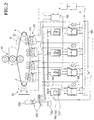
- the developer supply device 50 includes numerous circulation tanks 100 which store developers that are to be supplied to the developing unit 20, numerous injection nozzles 120 which spray the developer within each circulation tank 100 on to the development gap of the developing unit 20, numerous ink storage tanks 140 which store concentrated ink that correspond to respective colours that are to be supplied to the circulation tanks 100, a carrier storage tank 160 which stores the carrier that is to be supplied to the circulation tanks 100, a waste tank 180 for collecting used developers that come from the circulation tanks 100, and a developer filling and used-developer collecting unit 220 for recovering used-developers collected in the waste tank 180 with a refill cartridge that is empty inside, along with refilling the concentrated ink or carrier of a refill cartridge 200 to the ink storage tank 140 or carrier storage tank 160.
- the developer supply device 50 is provided with concentration measuring sensors 106 for measuring the concentration of the developer stored in the circulation tank, and an ink agitation device 150 for agitating the concentrated ink stored in the ink storage tank 140.
- the concentrated ink within the ink storage tank 140 of the developer supply device 50 has approximately a 17% Solid concentration, and the developer in the circulation tanks 100 has approximately 2.3 to 3.5% Solid concentrations.
- the actual requisite concentration is around 3%, but concentrated ink is used so that a larger amount of ink may be supplied using the same capacity ink storage tank. If, however, a more highly concentrated ink than that currently used is stored, the viscosity of the ink becomes too high and operations of appropriately dispersing and supplying the developer become difficult. Given the same amount of time since the ink was last agitated, an ink storage tank that contains highly concentrated developer requires more time to disperse the developer than that of the circulation tanks containing a developer of lower concentration.
- the ink agitator 150 which is provided in the developer supply device of a printer includes agitation wings 151 which are rotatably installed in each ink storage tank 140, a motor 152 which is the driving power source for the agitation wings 151, and force transmission unit 153 which conveys the driving force of the motor 152 to the agitation wings 151, as depicted in Figure 3.
- the force transmission unit 153 includes follower pulleys 153a, 153b, and 153c which are mounted on the upper end of the rotation shaft of the agitation wings 151, a driver pulley 153d which is mounted on the shaft of the motor, and a belt 153e which is installed such that it winds and goes around the follower pulleys 153a, 153b, and 153c and the driver pulley 153d.
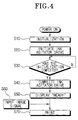
- Step S10 When power is turned on and the printer performs initializing operations (Step S10), the ink agitator is driven (Step S20) and starts to agitate the ink stored in the ink storage tanks. The driving of the ink agitator stops at the completion time of initialization (Step S30) and the agitation operation is completed (Step S40).
- the printer displays an indication that the printer is in the 'READY' state (Step S50), and when there is data to be printed (Step S60) the printer performs printing (Step S70).
- the initialization operation period of the printer is approximately 1.5 minutes to 2 minutes. That is, the agitator is driven for 1.5 to 2 minutes and dissolves deposits and lumps of ink by agitating the ink in the ink storage tanks 140.
- Figure 5 is a flow chart of the ink agitator control method according to one preferred embodiment of this invention.
- the method of the present invention may be applied to an electrophotographic printer such as the conventional one described heretofore. Therefore, in describing the method, by way of example, reference will be made to elements and reference numbers found in Figures 2 and 3. However, the method of the present invention is applicable to other printers having corresponding elements.
- the ink agitator control method involves checking, or determining, a non-usage time of the printer, for example the power 'off' time of the printer, before performing printing. The method then involves setting the driving time of the ink agitator 150 differently according to the determined non-usage time of the printer and then driving the agitator, thereby allowing the concentrated ink stored in the ink storage tanks 140 to be supplied to the circulation tanks 100 in a dispersed (dissolved) state.
- the printer when the power is turned on, the printer performs an initialization operation (Step S110).
- the non-usage time (t) of the printer is determined concurrently with the initialization operation (Step S120), that is, after the power is turned on and before printing is performed.
- the non-usage time may be the power "off" time, that is, the elapsed time from when the power was last turned off to when it is turned on.
- the step S120 includes the operations of recalling the time of the power of the printer being turned 'off' at a control circuit (not shown) and determining the elapsed time from the 'off' time to the time when the printer is turned 'on' again.
- the printer will have a clock which continues to function while the printer power is "off” and the control circuit may save the value of the current time in a memory at the time that the power is turned off.
- a timer which runs while the printer power is "off” may be started when the printer is turned off.
- Step S120 also includes classifying, by the control circuit, of the determined printer non-usage time value into one of at least three time range groups including a first selection time, a second selection time, and a third selection time, according to the length of the non-usage time and then storing the corresponding selection time value.
- the printer non-usage time may alternatively be classified using more than three range groups, in a more elaborate classification scheme. According to one embodiment of the present invention, classification is made using three time range groups in which the first selection time is two days or shorter, the second selection time is from three days to seven days, and the third selection time is from eight days to forty days.
- the control circuit sets the driving time of the ink agitator according to the classified non-usage time of the printer.
- the ink agitator driving time is set such that, if the printer non-usage time (t) is determined to be under the first selection time, the driving time is set to a first driving time (normal initialization operation time), if determined to be the second selection time, a second driving time, and if determined to be the third selection time, a third driving time.
- the third driving time is used as the agitation time.
- This method is used for the typical situation where, after the maximum value of the third selection time, the developer tends not to further deposit or form lumps, and the third driving time is adequate to sufficiently disperse the developer. Note that a typical lifetime of ink is approximately one and a half years.
- an embodiment of the invention has been tested with the agitator drive time set to approximately 2 minutes for under two days of non-usage time, 5 minutes for three to seven days, and 15 minutes for eight to forty days, and it has been experimentally verified that 100% of the concentrated ink is dispersed.
- these selection times may be varied depending on the temperature value of the separation transition of ink.
- the object of this invention does not relate to accurate time but rather to the providing of a control method requisite to the agitation of ink along with the initialization operation time of the printer, the selected selection times or driving times may fluctuate somewhat.
- Step S130 When the non-usage time (t) is classified to be under the first selection time (Step S130) as a result of the printer non-usage time determining step of S120, the ink agitator driving time is set to the first driving time and the agitator is driven (Step S140), and the printer completes normal initialization operation and may display 'READY' (Step S150). Then, if there is data to be printed (Step S160) , it performs printing (Step S170) and concludes the operation.
- the ink agitator driving time is set to the second driving time and the agitator is driven (Step S210).
- the ink agitator driving time is set to the second driving time which is longer than that of the normal initialization operation time (for example 1.5 to 2 minutes) and the initialization operation time of the printer is prolonged.
- this invention controls the printer such that the initialization operation is completed and 'READY' is displayed during the time when the agitation of the developer within the circulation tanks is completed while the ink agitator is being driven for the set time selected as above (Step S220). That is, initialization is completed and printing may begin before agitation is completed.
- the ink agitator may be continuously driven throughout the set time (Step 5230), and when the set time is reached, the driving of the ink agitator is stopped (Step S240).
- the ink agitator driving time is set to the third driving time and the agitator is driven (Step S310).
- initialization is completed and printing is enabled during the time when the agitation of the developer within the circulation tanks is performed while the ink agitator is being driven for the set time (Step S220).
- the ink agitator may be continuously driven throughout the set time (Step S230), and when the set time is reached, the driving of the ink agitator is stopped (Step S240).
- the ink agitator control method determines the printer non-usage time during the initialization operation of the printer, and the ink agitator driving time is selected and the agitator is driven according to the determined non-usage time, and thereby the driving of the ink agitator is controlled such that the agitator may completely dissolve deposits and lumps of ink within the ink storage tanks 140 even when the printer non-usage time has been long.
- the initialization operation time is kept uniform by completing the printer initialization operation during the time that the ink agitator is being driven to complete the agitation of the developer within the circulation tanks.
- the driving time of the ink agitator is variably selected according to the extent of deposition and lumping of concentrated ink, and the ink agitator is driven throughout the selected time and thereby the deposits and lumping of ink are completely dissolved. Therefore, because the ink stored in the ink storage tanks is supplied to the circulation tanks at a state having normal particle rate and concentration (density) distribution, the concentration of the developer may be maintained at a uniform rate and high quality clear images may be obtained.
- the initialization operation is not completed when the driving of the agitator is completed, but rather it is completed at the time when the agitation of the developer within the circulation tanks is completed while the ink agitator is being driven for the set time, and 'READY' is displayed and printing operations may be performed from that time on. That is to say, the initialization operation time of the printer may be maintained at a uniform state.
Landscapes
- Physics & Mathematics (AREA)
- General Physics & Mathematics (AREA)
- Ink Jet (AREA)
- Control Or Security For Electrophotography (AREA)
- Wet Developing In Electrophotography (AREA)
Abstract
Description
Claims (19)
- A method of controlling an ink agitator of a wet-type electrophotographic printer, comprising the steps of:after turning the printer power on and before printing, determining a value for the non-usage time of the printer;determining a value of ink agitator driving time which is dependent upon the determined value of the non-usage time; anddriving the ink agitator for the determined value of ink agitator driving time.
- The method of claim 1, further comprising: said steps of determining the value of the non-usage time and determining the value of the ink agitator driving time, and the beginning of driving the ink agitator, being performed during an initialization process of the printer.
- The method of claim 2, further comprising: when there are data to be printed, beginning printing after the initialization process is completed.
- The method of claim 2 or 3, further comprising: completing the initialization process at a fixed time after the printer power is turned on.
- The method of claim 2, 3 or 4, further comprising:
displaying an indication that the printer is ready after the initialization process is completed. - The method of claim 4 or 5 as dependent thereon, further comprising:
completing the initialization process before the driving of the ink agitator is finished. - The method of any preceding claim, said step of determining a value of ink agitator driving time further comprising:classifying the determined value of non-usage time into one of three groups of time ranges; anddetermining the value of ink agitator driving time as one of three respective driving time values which are respectively fixed for the time range groups.
- The method of any preceding claim, said non-usage time of the printer being the elapsed time from when the printer was last turned off until the printer is turned on.
- The method of claim 8, said step of determining the value of non-usage time of the printer further comprising:recalling a value of the time when the printer was last turned off; anddetermining the value of the non-usage time based on the recalled value and the current time.
- A method of controlling an ink agitator of a wet-type electrophotographic printer, comprising the steps of:said second driving time being greater than said first driving time and said third driving time being greater than said second driving time.when the printer is turned on, determining a value for the non-usage time of the printer;classifying the determined value of non-usage time into one of a first selection time range, a second selection time range whose minimum equals the maximum for the first selection time range, and a third selection time range whose minimum equals the maximum for the second selection time range; anddriving the agitator for a value of driving time which is a first, second or third driving time when the non-usage value is classified into the first selection time range, second selection time range or third selection time range, respectively;
- The method of claim 10, further comprising: when there are data to be printed, printing said data after said first driving time has elapsed from the start of driving the agitator.
- The method of claim 10 or 11, further comprising: after said first driving time has elapsed from the start of driving the agitator, displaying an indication that the printer is ready to print.
- The method of claim 11, further comprising:when the printer is turned on, beginning an initialization process of the printer; andcompleting the initialization process before said first driving time has elapsed from the start of driving the agitator.
- The method of claim 10, 11, 12 or 13, further comprising:
said first selection time range being times up to two days, said second selection time range being from three days through seven days, and said third time range being times greater than eight days. - The method of claim 10, 11, 12 or 13, further comprising:
said first selection time range being times up to two days, said second selection time range being from three days through seven days, and said third time range being from eight days through forty days. - The method of any of claims 10 to 15, further comprising:the value of driving time corresponding to said first selection time range being approximately 2 minutes;the value of driving time corresponding to said second selection time range being approximately 5 minutes; andthe value of driving time corresponding to said third selection time range being approximately 15 minutes.
- The method of any of claims 10 to 11, further comprising:when power to the printer is turned off, storing the current time value in a memory; andsaid step of determining the value for the non-usage time of a printer further comprising recalling the time value stored in said memory.
- The method of any of claims 10 to 17, further comprising:when power to the printer is turned off, starting a timer in the printer; andsaid step of determining the value for the non-usage time of a printer further comprising determining the value of said timer.
- A method of controlling an ink agitator of a wet-type electrophotographic printer, comprising the steps of:when the printer is turned on, determining a value for the non-usage time of the printer;classifying the determined value of non-usage time into one of a plurality of time ranges; anddriving the ink agitator for a value of driving time which is one of a set of fixed values, one fixed value associated with each of the plurality of time ranges.
Applications Claiming Priority (2)
| Application Number | Priority Date | Filing Date | Title |
|---|---|---|---|
| KR9951746 | 1999-11-20 | ||
| KR1019990051746A KR100337920B1 (en) | 1999-11-20 | 1999-11-20 | Method for controlling ink agitating device of a liquid electrophotographic color printer |
Publications (3)
| Publication Number | Publication Date |
|---|---|
| EP1102133A2 true EP1102133A2 (en) | 2001-05-23 |
| EP1102133A3 EP1102133A3 (en) | 2003-03-05 |
| EP1102133B1 EP1102133B1 (en) | 2004-11-17 |
Family
ID=19621036
Family Applications (1)
| Application Number | Title | Priority Date | Filing Date |
|---|---|---|---|
| EP00309711A Expired - Lifetime EP1102133B1 (en) | 1999-11-20 | 2000-11-02 | Method of controlling an ink agitator of a wet-type electrophotography printer |
Country Status (6)
| Country | Link |
|---|---|
| US (1) | US6341209B1 (en) |
| EP (1) | EP1102133B1 (en) |
| JP (1) | JP2001154492A (en) |
| KR (1) | KR100337920B1 (en) |
| CN (1) | CN1213351C (en) |
| DE (1) | DE60015905T2 (en) |
Families Citing this family (6)
| Publication number | Priority date | Publication date | Assignee | Title |
|---|---|---|---|---|
| JP2006106114A (en) * | 2004-09-30 | 2006-04-20 | Kyocera Mita Corp | Liquid developing device |
| KR100637075B1 (en) * | 2004-12-21 | 2006-10-23 | 삼성전자주식회사 | Developer cartridge |
| US7621627B2 (en) * | 2005-09-02 | 2009-11-24 | Canon Kabushiki Kaisha | Liquid container |
| ATE420771T1 (en) * | 2005-09-02 | 2009-01-15 | Canon Kk | LIQUID CONTAINER |
| JP4646745B2 (en) * | 2005-09-02 | 2011-03-09 | キヤノン株式会社 | Ink tank |
| JP5620591B2 (en) * | 2011-01-31 | 2014-11-05 | ヒューレット−パッカード デベロップメント カンパニー エル.ピー.Hewlett‐Packard Development Company, L.P. | Printing system using ink with high solids content |
Family Cites Families (6)
| Publication number | Priority date | Publication date | Assignee | Title |
|---|---|---|---|---|
| US4236810A (en) * | 1979-08-20 | 1980-12-02 | Sperry Corporation | Means for inhibiting the separation of toner particles from dispersant in a copy machine |
| JPH0715604B2 (en) * | 1985-11-19 | 1995-02-22 | カシオ計算機株式会社 | Image forming device |
| JPH01137278A (en) * | 1987-11-25 | 1989-05-30 | Nec Corp | Electrostatic transfer type plotter |
| JPH01173078A (en) * | 1987-12-28 | 1989-07-07 | Fuji Photo Film Co Ltd | Developer stirring mechanism |
| JPH0844175A (en) * | 1994-07-28 | 1996-02-16 | Fuji Xerox Co Ltd | Image forming device |
| US5652282A (en) | 1995-09-29 | 1997-07-29 | Minnesota Mining And Manufacturing Company | Liquid inks using a gel organosol |
-
1999
- 1999-11-20 KR KR1019990051746A patent/KR100337920B1/en not_active Expired - Fee Related
-
2000
- 2000-09-25 JP JP2000290777A patent/JP2001154492A/en active Pending
- 2000-11-02 EP EP00309711A patent/EP1102133B1/en not_active Expired - Lifetime
- 2000-11-02 DE DE60015905T patent/DE60015905T2/en not_active Expired - Fee Related
- 2000-11-20 US US09/714,969 patent/US6341209B1/en not_active Expired - Lifetime
- 2000-11-20 CN CNB001309153A patent/CN1213351C/en not_active Expired - Fee Related
Also Published As
| Publication number | Publication date |
|---|---|
| KR100337920B1 (en) | 2002-05-23 |
| EP1102133B1 (en) | 2004-11-17 |
| KR20010047495A (en) | 2001-06-15 |
| EP1102133A3 (en) | 2003-03-05 |
| DE60015905D1 (en) | 2004-12-23 |
| US6341209B1 (en) | 2002-01-22 |
| CN1213351C (en) | 2005-08-03 |
| JP2001154492A (en) | 2001-06-08 |
| CN1297170A (en) | 2001-05-30 |
| DE60015905T2 (en) | 2005-12-01 |
Similar Documents
| Publication | Publication Date | Title |
|---|---|---|
| US6999689B2 (en) | Image forming apparatus and method of controlling same | |
| CN100390677C (en) | Image forming apparatus | |
| JP7463716B2 (en) | Image forming device | |
| JP4450033B2 (en) | Developing device and image forming apparatus | |
| JPH11202630A (en) | Developing method and developing device using the same | |
| EP1102133B1 (en) | Method of controlling an ink agitator of a wet-type electrophotography printer | |
| CN105301931A (en) | Image forming apparatus | |
| JP4655113B2 (en) | Developing device and image forming apparatus having the developing device | |
| US4862213A (en) | Image forming apparatus and method | |
| US20100054818A1 (en) | Developing apparatus | |
| US20100054765A1 (en) | Developing device | |
| CN102854774A (en) | Developing device and image forming apparatus | |
| JPH06332313A (en) | Development device | |
| JPH0764452A (en) | Color electrophotographic device | |
| JP2013125072A (en) | Image forming apparatus and image forming method | |
| JP7449481B2 (en) | Image forming device | |
| JP2009244440A (en) | Developing device, image forming apparatus, and developer cartridge | |
| US20090129837A1 (en) | Developing device using recycled toner | |
| JP2006085022A (en) | Image forming apparatus | |
| JP4006371B2 (en) | Image forming apparatus | |
| JP5610927B2 (en) | Image forming apparatus | |
| JP2003270922A (en) | Image forming apparatus and toner supply method in the same | |
| JPH0651637A (en) | Toner replenishment controller for image forming device | |
| CN120507952A (en) | Determination method and recovery method | |
| JP4555248B2 (en) | Developing device, toner replenishing method for developing device, and image forming apparatus |
Legal Events
| Date | Code | Title | Description |
|---|---|---|---|
| PUAI | Public reference made under article 153(3) epc to a published international application that has entered the european phase |
Free format text: ORIGINAL CODE: 0009012 |
|
| 17P | Request for examination filed |
Effective date: 20001113 |
|
| AK | Designated contracting states |
Kind code of ref document: A2 Designated state(s): AT BE CH CY DE DK ES FI FR GB GR IE IT LI LU MC NL PT SE TR |
|
| AX | Request for extension of the european patent |
Free format text: AL;LT;LV;MK;RO;SI |
|
| PUAL | Search report despatched |
Free format text: ORIGINAL CODE: 0009013 |
|
| AK | Designated contracting states |
Designated state(s): AT BE CH CY DE DK ES FI FR GB GR IE IT LI LU MC NL PT SE TR Kind code of ref document: A3 Designated state(s): AT BE CH CY DE DK ES FI FR GB GR IE IT LI LU MC NL PT SE TR |
|
| AX | Request for extension of the european patent |
Extension state: AL LT LV MK RO SI |
|
| AKX | Designation fees paid |
Designated state(s): DE FR GB |
|
| 17Q | First examination report despatched |
Effective date: 20031212 |
|
| GRAP | Despatch of communication of intention to grant a patent |
Free format text: ORIGINAL CODE: EPIDOSNIGR1 |
|
| RIN1 | Information on inventor provided before grant (corrected) |
Inventor name: LEE, HYONG-GU Inventor name: KIM, JONG-WOO |
|
| GRAS | Grant fee paid |
Free format text: ORIGINAL CODE: EPIDOSNIGR3 |
|
| GRAA | (expected) grant |
Free format text: ORIGINAL CODE: 0009210 |
|
| AK | Designated contracting states |
Kind code of ref document: B1 Designated state(s): DE FR GB |
|
| REG | Reference to a national code |
Ref country code: GB Ref legal event code: FG4D |
|
| REG | Reference to a national code |
Ref country code: IE Ref legal event code: FG4D |
|
| REF | Corresponds to: |
Ref document number: 60015905 Country of ref document: DE Date of ref document: 20041223 Kind code of ref document: P |
|
| ET | Fr: translation filed | ||
| PLBE | No opposition filed within time limit |
Free format text: ORIGINAL CODE: 0009261 |
|
| STAA | Information on the status of an ep patent application or granted ep patent |
Free format text: STATUS: NO OPPOSITION FILED WITHIN TIME LIMIT |
|
| 26N | No opposition filed |
Effective date: 20050818 |
|
| PGFP | Annual fee paid to national office [announced via postgrant information from national office to epo] |
Ref country code: DE Payment date: 20081103 Year of fee payment: 9 |
|
| PGFP | Annual fee paid to national office [announced via postgrant information from national office to epo] |
Ref country code: FR Payment date: 20081112 Year of fee payment: 9 |
|
| PGFP | Annual fee paid to national office [announced via postgrant information from national office to epo] |
Ref country code: GB Payment date: 20081029 Year of fee payment: 9 |
|
| GBPC | Gb: european patent ceased through non-payment of renewal fee |
Effective date: 20091102 |
|
| REG | Reference to a national code |
Ref country code: FR Ref legal event code: ST Effective date: 20100730 |
|
| PG25 | Lapsed in a contracting state [announced via postgrant information from national office to epo] |
Ref country code: FR Free format text: LAPSE BECAUSE OF NON-PAYMENT OF DUE FEES Effective date: 20091130 |
|
| PG25 | Lapsed in a contracting state [announced via postgrant information from national office to epo] |
Ref country code: DE Free format text: LAPSE BECAUSE OF NON-PAYMENT OF DUE FEES Effective date: 20100601 |
|
| PG25 | Lapsed in a contracting state [announced via postgrant information from national office to epo] |
Ref country code: GB Free format text: LAPSE BECAUSE OF NON-PAYMENT OF DUE FEES Effective date: 20091102 |
|
| REG | Reference to a national code |
Ref country code: GB Ref legal event code: 732E Free format text: REGISTERED BETWEEN 20170406 AND 20170412 |
|
| REG | Reference to a national code |
Ref country code: FR Ref legal event code: TP Owner name: S-PRINTING SOLUTION CO., LTD., KR Effective date: 20170912 |