EP1102022A2 - Automatic weapon with recoiling barrel - Google Patents
Automatic weapon with recoiling barrel Download PDFInfo
- Publication number
- EP1102022A2 EP1102022A2 EP00310177A EP00310177A EP1102022A2 EP 1102022 A2 EP1102022 A2 EP 1102022A2 EP 00310177 A EP00310177 A EP 00310177A EP 00310177 A EP00310177 A EP 00310177A EP 1102022 A2 EP1102022 A2 EP 1102022A2
- Authority
- EP
- European Patent Office
- Prior art keywords
- barrel assembly
- weapon
- receiver
- bolt
- barrel
- Prior art date
- Legal status (The legal status is an assumption and is not a legal conclusion. Google has not performed a legal analysis and makes no representation as to the accuracy of the status listed.)
- Granted
Links
Images


Classifications
-
- F—MECHANICAL ENGINEERING; LIGHTING; HEATING; WEAPONS; BLASTING
- F41—WEAPONS
- F41A—FUNCTIONAL FEATURES OR DETAILS COMMON TO BOTH SMALLARMS AND ORDNANCE, e.g. CANNONS; MOUNTINGS FOR SMALLARMS OR ORDNANCE
- F41A5/00—Mechanisms or systems operated by propellant charge energy for automatically opening the lock
- F41A5/02—Mechanisms or systems operated by propellant charge energy for automatically opening the lock recoil-operated
-
- F—MECHANICAL ENGINEERING; LIGHTING; HEATING; WEAPONS; BLASTING
- F41—WEAPONS
- F41A—FUNCTIONAL FEATURES OR DETAILS COMMON TO BOTH SMALLARMS AND ORDNANCE, e.g. CANNONS; MOUNTINGS FOR SMALLARMS OR ORDNANCE
- F41A25/00—Gun mountings permitting recoil or return to battery, e.g. gun cradles; Barrel buffers or brakes
- F41A25/16—Hybrid systems
- F41A25/18—Hydroelastic systems
Definitions
- the present invention relates generally to automatic projectile firing weapons. More particularly, the invention relates to a method and apparatus for absorbing the recoil force of an automatic projectile firing weapon.
- a lightweight, easily portable automatic weapon that is capable of accurately firing a projectile over a significant distance would provide a decisive tactical advantage.
- Many existing small and medium caliber automatic weapons that are specifically designed to fill particular combat needs.
- weapons that are effective at ranges of up to 2,000 meters for example the 0.50 caliber M2 heavy machine gun and the 40mm Mk-19 grenade, are too bulky and heavy to be easily portable.
- Other automatic weapons like the 7.62mm M60/M240 medium machine guns and the 5.56mm M249 squad automatic weapon, are easily portable but are not effective at long ranges.
- the accuracy of a weapon at a long range is dependent upon the ability of the weapon to manage the recoil force of the fired projectile.
- the magnitude of the recoil force is a function of the mass and velocity of the projectile which directly effects the expected travel distance (range) of the fired projectile. As the expected range of the weapon increases, so does the magnitude of the recoil force.
- Weapons designed to fire projectiles over a significant distance typically have a greater weight than weapons designed to fire projectiles over a shorter range. The greater weight is necessary to restrain the more energetic cartridges, absorb the increased recoil force, and prevent the recoil force from disrupting the accuracy of the weapon.
- a counterweight is attached to the recoiling mass of the weapon to absorb the recoil energy.
- a spring is used to absorb and store the recoil force. The energy stored in the spring or counterweight can then be used to move the recoiling mass forward when the next projectile is fired. The forward momentum of the counter-recoiling mass will partially absorb the recoil force of the next projectile.
- the weapon and mount will overcome the recoil overload and achieve a steady state dynamic recoil action. If the weapon is flexibly mounted, it is likely the weapon will not become accurate and effective until the transient period is passed and the weapon enters this steady state recoil action. However, during the transient period, several projectiles are wasted before the weapon settles into the steady state recoil action. Furthermore, due to mount flexibility, a steady state recoil action can have significant effects on accuracy.
- the present invention is directed to an automatic projectile firing weapon that obviates one or more of the limitations and disadvantages of prior art automatic projectile firing weapons.
- the weapon includes a receiver that has a main sear and a trackway.
- a barrel assembly is slidably mounted in the trackway and is moveable between a rearward position and a forward position.
- the barrel assembly is engageable with the main sear at the rearward position.
- a firing position is located between the rearward position and the forward position and preferably closer to the forward position.
- an operating spring connected between the receiver and the barrel assembly. The operating spring biases the barrel assembly towards the forward position.
- a manual retracting device that moves the barrel assembly rearwardly into engagement with the main sear, thereby compressing the operating spring.
- a trigger is provided to release the main sear and allow the operating spring to move the barrel assembly forwardly along the trackway of the receiver.
- a buffer connected between the receiver and the barrel assembly to dampen the velocity of the barrel assembly to prevent the barrel assembly from exceeding a predetermined maximum velocity when a round is fired.
- the recoil energy from the fired round is absorbed in part by the forward motion of the barrel assembly and in part by the operating spring.
- the recoil force felt by the receiver is that of the operating spring and, in part, the buffer.
- the invention is directed to a method of absorbing the recoil force of a projectile firing weapon.
- the weapon includes a barrel assembly slidably mounted in a receiver and an operating spring connected between the receiver and the barrel assembly.
- the method involves compressing the operating spring by retracting the barrel assembly within the receiver to engage the barrel assembly with a main sear when the operating spring is fully compressed. The main sear is released to allow the operating spring to bias the barrel assembly forwardly within the receiver.
- a round is chambered as the barrel assembly moves forwardly along the trackways. The forward motion of the barrel assembly is buffered to prevent the barrel assembly from exceeding a predetermined maximum velocity. The round is fired when the barrel assembly reaches a predetermined location in the receiver.
- the recoil force of the fired shot reverses the motion of the barrel assembly to move the barrel assembly rearward and re-compress the operating spring.
- the buffer is configured to maintain a nearly constant dynamic condition of the barrel assembly during the firing and recoil portions of the operating cycle so that effects of varying friction, weapon attitude, and cartridge impulse on the weapon operating cycle are minimized.
- an automatic projectile firing weapon is provided.
- the exemplary embodiment of the weapon of the present invention is a lightweight automatic crew served weapon for firing medium caliber munitions.
- the present invention contemplates, however, that the principles and methods disclosed herein are applicable to automatic weapons of all sizes.
- the exemplary embodiment of the automatic projectile firing weapon of the present invention is shown in Fig. 1 and is designated generally by the reference number 20.
- weapon 20 includes a receiver 22, a mount 26, and a pair of handles 30 that are attached to receiver 22.
- Mount 26 allows weapon 20 to be pivoted horizontally (traverse) and vertically (elevation) to provide a full range of firing directions.
- Handles 30 can be manipulated to horizontally or vertically pivot the weapon about mount 26 to adjust the aim of weapon 20.
- Mount 26 connects receiver 22 to a flexible structure.
- weapon 20 is mounted on a tripod 28.
- the present invention contemplates, however, that weapon 20 may be mounted on any other flexible structure readily apparent to one skilled in the art, such as, for example, a moving vehicle.
- the weapon 20 also includes a targeting device 36.
- Targeting device 36 may include direct view optics and a laser targeting system or any other range finding instrument readily apparent to one skilled in the art.
- targeting device 36 may also include a display screen to display information from the laser targeting system or other information regarding firing status of the weapon.
- each of the pair of handles 30 may include a set of buttons 56. Buttons 56 may be used to activate the laser targeting system or perform any standard operating function of targeting device 36.
- the weapon includes a barrel assembly that is slidably mounted within the receiver.
- the barrel assembly is moveable between a rearward position and a forward position and has a firing position between the rearward and forward positions.
- An operating spring is connected between the receiver and the barrel assembly. The operating spring biases the barrel assembly forwardly within the receiver.
- the barrel assembly is slidably mounted on a trackway in the receiver. The present invention contemplates that other types of mountings will be readily apparent to one skilled in the art.
- weapon 20 includes a receiver 22.
- a barrel assembly 34 is contained within the receiver 22.
- an operating spring 44 is disposed on a guide 46. Operating spring 44 is connected between receiver 22 and barrel assembly 34 so that a rearward movement of barrel assembly 34 operates to compress operating spring 44.
- a buffer (not shown) is also connected between the barrel assembly 34 and the receiver 22.
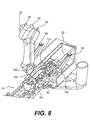
- receiver 22 includes an operating spring compartment 72, a buffer compartment 74, and tracks 70.
- Operating spring 44 and guide 46 are positioned within operating spring compartment 72 of receiver 22.
- Barrel assembly 34 includes trackways 84 (referring to Fig. 6) that correspond to and engage tracks 70. This engagement is configured to allow barrel assembly 34 to slide within receiver 22 between a forward and a rearward position.
- receiver 22 also includes an ammunition feed opening 76, 77 on either side of weapon 20.
- an ammunition can 24 (referring to Fig. 1 ) is mounted, on either side of the weapon, adjacent either ammunition feed opening 76, 77 on receiver 22 to provide ammunition to weapon 20.
- Ammunition can 24 is positioned external to receiver 22, on either side of the weapon, to allow easy removal and replacement during operation of the weapon.
- the ammunition may be fed to the weapon by any means readily apparent to one skilled in the art.
- an ammunition feed sprocket 54 is provided within receiver 22 to advance the ammunition through the weapon. Feed sprocket 54 moves the ammunition from ammunition can 24 to a strip position adjacent and above the barrel assembly 34.
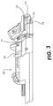
- receiver 22 also includes a cocking lever trip 79.
- Cocking lever trip 79 is located in a fixed position toward the front end of receiver 22 along tracks 70.
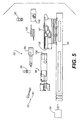
- barrel assembly 34 includes a barrel 52, a barrel extension 60 and a bolt assembly 42.
- Barrel 52 includes a chamber 88 and breech locking lugs 89.
- Barrel extension 60 extends rearward from barrel 52 and defines a track 112.
- Bolt assembly 42 is slidably positioned in track 112. Preferably, the sliding motion of bolt assembly 42 is limited on the forward end by chamber 88 and on the rearward end by a bolt bumper 86.
- bolt assembly 42 includes a bolt carriage 92, a gas shut-off valve 94, a bolt body 96, and a bolt spring (not shown) disposed within bolt carriage 92.
- bolt carriage 92 is slidably disposed within a gas cylinder 82 of barrel assembly 34.
- the gas cylinder 82 is an integral part of barrel extension 60.
- the bolt spring acts on bolt carriage 92 to move bolt carriage 92 forwardly within track 112 and gas cylinder 82 of barrel extension 60.
- Bolt assembly is engageable with a bolt sear (not shown) to hold the bolt assembly rearward and hold the bolt spring in a compressed condition.
- bolt carriage 92 includes an opening 108 to receive bolt body 96 that includes a spring operated rammer 93.
- Rammer 93 strips a round of ammunition from the ammunition feed belt and feed sprocket 54 as operating spring 44 (referring to Fig. 2) urges barrel assembly 34 forwardly within barrel extension 60.
- the bolt spring urges bolt assembly 42 forwardly until the stripped round is rammed and locked into chamber 88.
- Bolt assembly 42 includes a cam pin 90 that engages bolt body 96 and a cam surface 91 in bolt carriage 92. As bolt carriage 92 moves forward, cam pin 90 rides along cam surface 91 to convert the linear motion of bolt carriage 92 into a rotary motion of bolt body 96, to engage the bolt body lugs with barrel lugs 89 (referring to Fig. 4). A carriage buffer 102 removes any excess energy of the bolt carriage.
- bolt body 96 includes an internal opening 106, which houses a firing pin 98, a firing spring 100, and a spring seat/carriage buffer 102.
- the final portion of bolt ram is utilized to charge firing spring 100 into cocked position.
- Firing spring 100 is released when cocking lever 99 contacts cocking lever trip 79 (referring to Fig. 3a) mounted in the receiver 22.
- Firing spring 100 urges firing pin 98 into contact with the round.
- the force of the contact between firing pin 98 and the percussion primer causes the cartridge to fire.
- Propellant gas from the fired round is directed into gas cylinder 82 through gas port 83 (referring to Fig. 4).
- the propellant gas contacts the gas piston of carriage and gas shutoff valve 94 and causes bolt assembly 42 to move rearwardly in track 112.
- a muzzle device 32 is affixed to the muzzle end of barrel 52.
- Muzzle device 32 may house muzzle velocity correction components.
- Muzzle device 32 also operates to shield muzzle gas, hide muzzle flash, and act as a muzzle brake, which reduces net impulse delivered to the weapon.
- a manual retracting device is provided.
- the retracting device is configured to engage the barrel assembly, prior to firing, to move the bolt assembly rearwardly into engagement with the bolt sear and to move the barrel assembly rearwardly within the receiver and into engagement with the main sear.
- the retracting device includes a pawl that is engageable with the bolt assembly to retract the barrel assembly. It is contemplated that alternative devices for retracting the barrel assembly will be readily apparent to one skilled in the art.
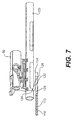
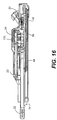
- a manual retracting device 110 is positioned alongside the rear portion of barrel assembly 34.
- Retracting device 110 includes a handle 40 and a guide tube 114.
- Handle 40 is connected to a cable 116 that is disposed in guide tube 114 (referring to Fig. 7).
- a pawl 122 and pawl carriage 120 are connected to the end of cable 116 opposite handle 40.
- a return spring 118 is disposed around cable 116 between handle 40 and pawl carriage 120.
- Pawl 122 pivots about a pin 128 in pawl carriage 120.
- Pawl 122 is spring loaded out and configured to engage a slot 124 in bolt carriage 92.
- pawl 122 engages slot 124 and moves bolt carriage 92 rearwardly along track 112 in barrel extension 60.
- Bolt carriage 92 moves rearwardly, compressing the bolt spring until bolt assembly 42 engages bolt bumper 56 and the bolt sear (not shown).
- the continuing rearward motion of handle 40 and pawl 122 then causes the entire barrel assembly 34 to move rearwardly within receiver 22.
- the rearward motion of barrel assembly 34 compresses operating spring 44 and continues until barrel assembly 34 engages main sear
- bolt carriage has a second slot 126.
- the handle must be retracted twice (equivalent to two half strokes) to move the barrel assembly into engagement with the main sear.
- the return spring 118 of the retracting device 110 urges pawl carriage 120 forwardly within guide tube 114.
- Spring loaded pawl 122 pivots inwardly and rides along the surface of bolt carriage 92 until pawl 122 reaches second slot 126.
- Handle 40 is then retracted a second half stroke to engage barrel assembly 34 with main sear 130.
- barrel assembly 34 includes a sear lug 131 on the carriage that engages main sear 130 at the fully rearward position.
- Main sear 130 is mounted on a trigger shaft 134 within the back cover portion of receiver 22.
- Triggers 38 are connected to trigger shaft 134. Depressing either or both of triggers 38 causes trigger shaft 134 to rotate. The rotation of trigger shaft 134 disengages main sear 130 from barrel assembly 34 and allows operating spring 44 to move the barrel assembly forward and initiate the firing sequence.
- receiver 22 also includes a semi-automatic sear 132.
- Semi-automatic sear 132 is also engageable with barrel assembly 34.
- Semi-automatic sear 132 may also be mounted on trigger shaft 134 such that if the selector is in the semi-automatic mode, a depression of either or both triggers 38 will cause semi-automatic sear 132 to maintain engagement with barrel assembly 34 after the first shot.
- semi-automatic sear 132 will engage barrel assembly 34 after each round is fired, even when the trigger is depressed.
- a buffer is connected between the receiver and the barrel assembly.
- the buffer dampens the movement of the barrel assembly to prevent the barrel assembly from exceeding a predetermined maximum velocity when a round is fired.
- the buffer maintains a nearly constant force, the magnitude of which is governed by the initial recoil velocity of the barrel assembly, through the rearward travel of the barrel assembly, thereby mitigating the recoil load.
- the disclosed buffer utilizes a damping fluid and shuttle valves to govern the motion of the barrel assembly, although it is contemplated that other alternatives will be readily apparent to one skilled in the art.
- a buffer 140 is provided having a housing 146 and a piston rod 142.
- a first connecting device 144 is positioned on one end of piston rod 142 and a second connecting device 148 is positioned on one end of housing 146.
- Buffer 140 is positioned within a buffer compartment 74 of receiver 22 (referring to Fig. 3).
- Connecting device 144 connects piston rod 142 to barrel assembly 34.
- Connecting device 148 connects housing 146 to receiver 22. Movement of barrel assembly 34 relative to receiver 22 results in a corresponding movement of piston rod 142 relative to housing 146.
- buffer 140 includes a reserve 150 of damping fluid, a stationary sleeve 156, and a moving sleeve 158.
- Stationary sleeve 156 is fixed within housing 146 and moving sleeve 158 is slidably disposed within stationary sleeve 156.
- a valve spring 160 is positioned on each side of moving sleeve 158 to center moving sleeve 158 within housing 146.
- a piston 152 is connected to piston rod 142 and is slidably disposed within moving sleeve 158.
- a seal 154 is disposed around piston 152 to prevent damping fluid from flowing between piston 152 and moving sleeve 158.
- a seal 162 is positioned at opening 166 in moving sleeve 158 through which piston rod 142 passes.
- the stationary sleeve 156 includes a plurality of buffering orifices 164.
- the moving sleeve 158 includes a corresponding plurality of buffering orifices 166 and a plurality of larger valve orifices 166.
- the buffering orifices 166 on moving sleeve 158 are offset from the buffering orifices 164 on stationary sleeve 156.
- valve orifices 168 are large enough that there is little resistance to the movement of piston 152 when the piston is moving at a low velocity. However, as the velocity of piston 152 increases and the rate of flow of fluid through valve orifices 168 increases, the resistance encountered by piston 152 also increases. The increased resistance encountered by piston 152 is opposed by the force of valve spring 160 acting on moving sleeve 158. When the piston reaches a certain velocity, the force exerted by piston 152 on moving sleeve 158 overcomes the force of valve spring 160 and causes moving sleeve 158 to slide within stationary sleeve 156.
- the movement of the moving sleeve 158 within the stationary sleeve 156 moves the valve orifices 168 and 169 out of alignment and causes buffering orifices 164 and 166 to align. Because buffering orifices 164 and 166 are smaller than valve orifices 168 and 169, moving piston 152 encounters a greater resistance in forcing fluid through buffering orifices 164 into reserve 150. This increased resistance on piston 152 causes a decrease in piston 152 velocity. As the velocity of piston 152 decreases so does the force exerted on moving sleeve 158.
- buffer 140 operates to prevent the velocity of piston 152 and connected barrel assembly 34 from exceeding a predetermined maximum velocity.
- moving sleeve 158 and stationary sleeve 156 have a second set of buffering orifices 153 and 155, respectively.
- the second set of buffering orifices are positioned such that the velocity of movement of piston 152 in the opposite direction may also be prevented from exceeding a predetermined maximum velocity. In this manner, buffer 140 can govern the velocity of movement of barrel assembly 34 in both directions.
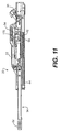
- the operation of the automatic projectile weapon of the present invention begins with weapon 20 in the un-charged position as illustrated in Fig. 11.
- the barrel assembly 34 is in the forward position.
- the operating spring 44 and bolt spring 95 are at their extended lengths and minimum preloads.
- the bolt assembly 42 is in its forward and locked position within the barrel extension 60.
- the ready round 170 (the next round to be fired) is within the ammunition feed sprocket 54.
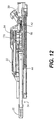
- the handle 40 of retracting device 110 is then pulled to charge weapon 20. As illustrated in Fig. 12, the charging stroke compresses bolt spring 95 and operating spring 44. In an alternative embodiment, handle 40 is pulled twice to fully compress the bolt spring and operating spring 44 in sequence.
- Feeder sprocket 54 advances ready round 170 into the strip position in front of bolt assembly 42.
- the feed sprocket advances one pocket position.
- the cam follower on top of the barrel extension via engagement with the feed cam, causes approximately 60° rotation of the 6 tooth sprocket with a 6" stroke of barrel extension.
- the feed cam drives the feed sprocket via a cam pawl.
- the feed sprocket is retained in the indexed position with a sprocket pawl.
- the feed cam rotates back 60°, which moves the cam pawl back one pocket or position. The weapon is now ready to fire.
- An optional procedure for preparation of the weapon for firing is to charge the weapon as described above, but without ammunition or unloaded. With the weapon charged, the ammunition belt is introduced into the feed port and the sprocket is manually indexed to position the first cartridge at the belt strip position. This is accomplished simply by overriding the sprocket pawl.
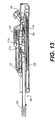
- Depressing trigger 38 releases the entire barrel assembly 34 from main sear 130, thereby allowing operating spring 44 to move barrel assembly 34 forward within the receiver 22.
- bolt assembly 42 via the spring loaded rammer, strips ready round 170 from feed sprocket 54.
- the bolt sear releases bolt carriage 92, allowing the bolt spring to move bolt carriage 92 forwardly within barrel assembly 34, while the barrel assembly continues to move forward relative to receiver 22.
- a fixed guide 172 within receiver 22 directs ready round 170 toward the centerline of barrel 52. Round 170 is further guided into chamber 88 by fixed guides within the barrel extension 60.
- the full expansion of the bolt spring causes bolt assembly 42 to lock round 170 in chamber 88. This is accomplished by the final portion of the longitudinal stroke of the carriage causing rotation of the bolt behind the chambered cartridge.
- the bolt is interconnected to the carriage via a lock pin 90 (referring to Fig. 5) through the bolt which engages lock cam way 91 of the carriage.
- the lock rotation (of approximately 54° in this embodiment) is driven by the carriage longitudinal stroke (of approximately 0.85")
- the forward velocity of barrel assembly 34 is governed by buffer 140 to ensure the barrel assembly does not exceed a predetermined maximum velocity.
- firing pin spring 100 Upon reaching a fixed position in receiver 22, firing pin spring 100 is released to urge firing pin 98 into contact with round 170. The contact results in round 170 being fired.
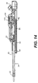
- Propellant gas from the fired round accelerates the projectile through barrel 52.
- bleed gas is directed through gas port 83 into gas chamber 82 to move bolt assembly 42 rearwardly in barrel extension 60 accomplishing unlock of the bolt and extraction of the spent casing from the chamber.
- the spent casing 174 is ejected from the bolt face as another round 176 is advanced by feed sprocket 54.
- Bolt assembly 42 moves rearwardly within barrel extension 60 to compress the bolt spring and re-engage the bolt sear.
- the maximum forward velocity of barrel assembly 34 allowed by buffer 140 is chosen to ensure that the forward momentum of the barrel assembly is not great enough to cancel the recoil impulse of the round and that the remainder of the recoil impulse is great enough to move barrel assembly 34 to the rearward position.
- the maximum rearward velocity of barrel assembly 34 allowed by buffer 140 is chosen to accomplish the feed index function, recompress the main spring, and to prevent the barrel assembly from moving too far rearwardly within receiver 22.
- barrel assembly 34 engages semi-automatic sear 132 at the rearward position. Depression of trigger 38 releases barrel assembly 34 and the firing sequence is repeated.
- the automatic projectile firing weapon of the present invention provides a recoil device that allows the weapon to achieve a steady state dynamic recoil action on the first shot and every shot thereafter.
- This recoil device minimizes the deleterious effects of conventional gun recoil on lightweight weapon system accuracy.
- the natural firing rate of the barrel assembly and the gas operation of the bolt further reduce the transmission of recoil forces to the receiver. This reduction of recoil force permits a lightweight weapon and mount configuration, while retaining dynamic stability.
- the lightweight configuration enhances weapon system capabilities in transport, deployment and field operation.
Landscapes
- Engineering & Computer Science (AREA)
- General Engineering & Computer Science (AREA)
- Toys (AREA)
- Aiming, Guidance, Guns With A Light Source, Armor, Camouflage, And Targets (AREA)
Abstract
Description
Claims (20)
- An automatic projectile firing weapon, the weapon comprising:a receiver having a main sear and a trackway;a barrel assembly slidably mounted in said trackway and moveable between a rearward position and a forward position, said barrel assembly being engageable with said main sear at the rearward position and having a firing position between the rearward position and the forward position;an operating spring connected between said receiver and said barrel assembly, said operating spring biasing said barrel assembly toward the forward position;a manual retracting device operable to move said barrel assembly rearwardly into engagement with said main sear, thereby compressing said operating spring;a trigger for releasing said main sear, thereby allowing said operating spring to move said barrel assembly forwardly; anda buffer connected between said receiver and said barrel assembly to dampen the velocity of said barrel assembly such that said barrel assembly is moving at a predetermined maximum velocity when a round is fired, whereby the recoil energy from firing said round is absorbed in part by the forward motion of said barrel assembly and in part by said operating spring.
- The weapon of claim 1, wherein the receiver further includes a cocking lever trip defining the firing position of the barrel assembly, the cocking lever trip configured to engage the barrel assembly as the barrel assembly moves towards the forward position.
- The weapon of claim 1, wherein the retracting device comprises:a pawl engageable with said barrel assembly; anda handle to move said pawl to engage and retract said barrel assembly into engagement with said main sear.
- The weapon of claim 3, wherein the retracting device further comprises:
a guide tube having a longitudinal slot, said pawl projecting through said slot such that said slot guides movement of said pawl. - The weapon of claim 3, wherein said barrel assembly includes a bolt carriage having a slot, said pawl being configured to engage said slot to retract said bolt carriage within the barrel assembly.
- The weapon of claim 5, wherein said bolt carriage has a second slot, said pawl being engageable with said first slot to retract said bolt carriage within the barrel assembly and engageable with said second slot to retract said barrel assembly into engagement with said main sear.
- The weapon of claim 1, wherein the buffer includes a housing for containing a damping fluid, a shuttle valve slidably disposed within said housing and having a plurality of orifices, and a piston connected to said receiver and having a head slidably disposed within said shuttle valve, wherein the velocity of movement of said piston head is governed by the rate of movement of the damping fluid through said plurality of orifices between said shuttle valve and said housing.
- The weapon of claim 1 wherein said buffer is operable to dampen the velocity of said barrel assembly in both the forward and rearward directions.
- The weapon of claim 2, wherein said barrel assembly includes a barrel having a chamber and locking lugs, a barrel extension, and a bolt assembly slidably mounted in the barrel extension and having a bolt, a bolt carriage, a bolt spring, and a firing mechanism, said bolt spring acting to bias said bolt assembly forward relative to said barrel assembly to load and lock a round into said barrel chamber, said firing mechanism being configured to fire said chambered round when said barrel assembly is moving forward and said barrel assembly reaches said firing location and engages cocking lever trip.
- The weapon of claim 9, wherein said weapon is disposed to fire a projectile from a cartridge, said bolt assembly including a piston, said piston operating to use gas from a fired round to propel said bolt assembly rearwardly relative to said barrel assembly thereby unlocking said bolt and extracting said cartridge and compressing said bolt spring.
- The weapon of claim 1, wherein said projectile firing weapon is a lightweight automatic crew served weapon.
- The weapon of claim 1, including a mount, said mount being connected to said receiver such that said weapon may be positioned on a rigid structure.
- The weapon of claim 12, wherein said weapon is fixedly positioned on said rigid structure.
- The weapon of claim 12, wherein said weapon is moveably positioned on said rigid structure.
- The weapon of claim 12, wherein said mount is connected to said weapon such that said receiver may pivot vertically.
- The weapon of claim 12, wherein said mount is connected to said weapon such that said gun receiver may pivot horizontally.
- The weapon of claim 12, wherein said rigid structure is a portable tripod.
- A method of absorbing the recoil force of an automatic projectile firing weapon having a receiver, a barrel assembly slidably mounted in the receiver, and an operating spring connected between the receiver and the barrel assembly, the method comprising the steps of:compressing said operating spring by retracting said barrel assembly within said receiver to engage said barrel assembly with a main sear when said operating spring is fully compressed;initiating a firing cycle by releasing said main sear to allow said operating spring to bias said barrel assembly forwardly within said receiver;chambering a round to be fired as said barrel assembly moves forward;buffering the forward motion of said barrel assembly to prevent the barrel assembly from exceeding a predetermined maximum velocity; andfiring the round when said barrel assembly reaches a predetermined location in said receiver, the impulse of the fired round reversing the motion of said barrel assembly such that said barrel assembly moves rearwardly to fully compress the operating spring.
- The method of claim 18, further comprising the step of buffering the rearward motion of said barrel assembly to prevent the barrel assembly from exceeding a predetermined maximum rearward velocity.
- The method of claim 18, wherein said predetermined location in said receiver is defined by a cocking lever trip.
Applications Claiming Priority (2)
| Application Number | Priority Date | Filing Date | Title |
|---|---|---|---|
| US09/441,195 US6343536B1 (en) | 1999-11-16 | 1999-11-16 | Automated projectile firing weapon and related method |
| US441195 | 1999-11-16 |
Publications (3)
| Publication Number | Publication Date |
|---|---|
| EP1102022A2 true EP1102022A2 (en) | 2001-05-23 |
| EP1102022A3 EP1102022A3 (en) | 2002-07-24 |
| EP1102022B1 EP1102022B1 (en) | 2006-03-01 |
Family
ID=23751915
Family Applications (1)
| Application Number | Title | Priority Date | Filing Date |
|---|---|---|---|
| EP00310177A Expired - Lifetime EP1102022B1 (en) | 1999-11-16 | 2000-11-16 | Automatic weapon with recoiling barrel |
Country Status (4)
| Country | Link |
|---|---|
| US (1) | US6343536B1 (en) |
| EP (1) | EP1102022B1 (en) |
| DE (1) | DE60026251T2 (en) |
| NO (1) | NO319430B1 (en) |
Cited By (5)
| Publication number | Priority date | Publication date | Assignee | Title |
|---|---|---|---|---|
| SG102669A1 (en) * | 2002-03-13 | 2004-03-26 | Ordnance Dev And Engineering C | Recoil mitigation mechanism |
| WO2005080904A3 (en) * | 2003-10-31 | 2005-12-08 | Ra Brands Llc | Action rate control system |
| TWI414744B (en) * | 2011-03-04 | 2013-11-11 | Military Academy | 7.62 mm general machine gun with the shooting module |
| WO2014080236A1 (en) * | 2012-11-26 | 2014-05-30 | Ifj Szabó Endre | Long recoil self-loading gun |
| EP2748552A4 (en) * | 2011-08-23 | 2015-07-15 | Gen Dynamics Ots Inc | LOW-RELEASE PULSE WEATHER CONTROL GROUP ARMY SYSTEM |
Families Citing this family (24)
| Publication number | Priority date | Publication date | Assignee | Title |
|---|---|---|---|---|
| US7698987B2 (en) * | 2002-06-07 | 2010-04-20 | Gamma Kdg Systems Sa | Heavy caliber firearm with enhanced recoil and control characteristics |
| US7201094B2 (en) | 2002-06-07 | 2007-04-10 | Gamma Kdg Systems Sa | Firearm with enhanced recoil and control characteristics |
| US9038524B2 (en) * | 2002-06-07 | 2015-05-26 | Kriss Systems Sa | Firearm with enhanced recoil and control characters |
| CA2724276C (en) | 2002-06-07 | 2013-03-26 | Kriss Systems Sa | Recoil control device |
| US6644168B1 (en) * | 2002-08-12 | 2003-11-11 | General Dynamics Armament And Technical Products, Inc. | System and method for active control of recoil mechanism |
| US7137217B2 (en) * | 2004-05-28 | 2006-11-21 | Knight's Armament Company | Auto-loading firearm mechanisms and methods |
| US7526991B2 (en) * | 2005-09-30 | 2009-05-05 | General Dynamics Armament And Technical Products | Over riding chamber impulse average weapon |
| US7584691B2 (en) * | 2006-08-03 | 2009-09-08 | General Dynamics Armament And Technical Products | Self-powered impulse averaging recoil operated machine gun with a rotary lock bolt driven by bimodal cams |
| US7568422B1 (en) * | 2006-09-28 | 2009-08-04 | Christopher Gene Barrett | Bolt operation facility for autoloading firearm |
| US7762174B1 (en) * | 2007-06-01 | 2010-07-27 | General Dynamics Armament And Technical Products | Ammunition container and feed system |
| DE102007051246A1 (en) | 2007-10-26 | 2009-04-30 | Krauss-Maffei Wegmann Gmbh & Co. Kg | Small or medium caliber machine gun |
| US8176837B1 (en) | 2009-10-11 | 2012-05-15 | Jason Stewart Jackson | Firearm operating rod |
| US8640598B1 (en) | 2010-07-19 | 2014-02-04 | Jason Stewart Jackson | Sleeve piston for actuating a firearm bolt carrier |
| US9261314B1 (en) | 2010-07-19 | 2016-02-16 | Jason Stewart Jackson | Sleeve piston for actuating a firearm bolt carrier |
| US9217614B2 (en) * | 2011-02-11 | 2015-12-22 | Jorge Pizano | Firearm having an articulated bolt train with transversally displacing firing mechanism, delay blowback breech opening, and recoil damper |
| RU2529247C1 (en) * | 2013-04-09 | 2014-09-27 | Открытое акционерное общество "Конструкторское бюро приборостроения им. академика А.Г. Шипунова" | Grenade launcher complex |
| USD860369S1 (en) | 2017-06-02 | 2019-09-17 | Sig Sauer, Inc. | Suppessor heat shield |
| USD859566S1 (en) * | 2017-06-02 | 2019-09-10 | Sig Sauer, Inc. | Suppressor heat shield assembly |
| HRP20240792T1 (en) | 2018-04-25 | 2024-09-27 | Sig Sauer, Inc. | Recoil assembly for a rifle |
| US10746493B1 (en) | 2019-08-19 | 2020-08-18 | Sig Sauer, Inc. | Recoil assembly for a machine gun |
| IL274417B2 (en) * | 2020-05-03 | 2024-11-01 | The State Of Israel Israel Nat Police | An assault weapon and a slingshot to neutralize an improvised explosive device |
| CN115046423B (en) * | 2022-06-30 | 2023-09-22 | 北京理工大学 | A lightweight weapon arm device |
| US12117257B1 (en) | 2022-09-09 | 2024-10-15 | Ryan Vanaken | Recoil reducing electromagnet system for firearms |
| CN118705933B (en) * | 2024-06-12 | 2025-11-21 | 南京理工大学 | Portable low-overload ejection device using clean energy |
Family Cites Families (12)
| Publication number | Priority date | Publication date | Assignee | Title |
|---|---|---|---|---|
| US2212687A (en) | 1937-06-18 | 1940-08-27 | Milton Roberts | Recoil device for machine guns |
| US3677135A (en) * | 1969-11-19 | 1972-07-18 | Us Army | Machine gun having a firing system means for obtaining substantially constant and minimum recoil forces |
| CH565359A5 (en) | 1973-05-04 | 1975-08-15 | Oerlikon Buehrle Ag | |
| AT331675B (en) | 1973-05-24 | 1976-08-25 | Heckler & Koch Gmbh | AUTOMATIC HANDGUN |
| US3919918A (en) * | 1974-07-26 | 1975-11-18 | Us Army | Electronic firing device for soft recoil weapons |
| US4072082A (en) | 1974-11-04 | 1978-02-07 | General Electric Company | Recoil converter |
| DE2658770C2 (en) | 1976-12-24 | 1983-12-08 | Rheinmetall GmbH, 4000 Düsseldorf | Device on an automatic barrel weapon to control the firing sequence (cadence) |
| WO1986002153A1 (en) * | 1984-10-05 | 1986-04-10 | Rostocil Charles E | Heavy support weapon |
| US5014595A (en) * | 1988-09-16 | 1991-05-14 | Ducolon Jr Fredric D | Redirected recoil mechanism |
| US5123329A (en) * | 1989-12-15 | 1992-06-23 | Irwin Robert M | Self-actuating blow forward firearm |
| US5138931A (en) * | 1991-07-12 | 1992-08-18 | Brookshire Harold C | Reduced recoil gun |
| US5585590A (en) * | 1995-05-05 | 1996-12-17 | Ducolon; Fredric D. | Recoil counter-vectoring gun |
-
1999
- 1999-11-16 US US09/441,195 patent/US6343536B1/en not_active Expired - Lifetime
-
2000
- 2000-11-14 NO NO20005760A patent/NO319430B1/en not_active IP Right Cessation
- 2000-11-16 DE DE60026251T patent/DE60026251T2/en not_active Expired - Lifetime
- 2000-11-16 EP EP00310177A patent/EP1102022B1/en not_active Expired - Lifetime
Cited By (8)
| Publication number | Priority date | Publication date | Assignee | Title |
|---|---|---|---|---|
| SG102669A1 (en) * | 2002-03-13 | 2004-03-26 | Ordnance Dev And Engineering C | Recoil mitigation mechanism |
| WO2005080904A3 (en) * | 2003-10-31 | 2005-12-08 | Ra Brands Llc | Action rate control system |
| US7775149B2 (en) | 2003-10-31 | 2010-08-17 | Ra Brands, L.L.C. | Action rate control system |
| TWI414744B (en) * | 2011-03-04 | 2013-11-11 | Military Academy | 7.62 mm general machine gun with the shooting module |
| EP2748552A4 (en) * | 2011-08-23 | 2015-07-15 | Gen Dynamics Ots Inc | LOW-RELEASE PULSE WEATHER CONTROL GROUP ARMY SYSTEM |
| EP2748553A4 (en) * | 2011-08-23 | 2015-10-28 | Gen Dynamics Ots Inc | LOW-BACK PULSE WEAPON ARM SYSTEM |
| US9383156B2 (en) | 2011-08-23 | 2016-07-05 | General Dynamics—OTS, Inc. | Quick release barrel attaching and detaching mechanism |
| WO2014080236A1 (en) * | 2012-11-26 | 2014-05-30 | Ifj Szabó Endre | Long recoil self-loading gun |
Also Published As
| Publication number | Publication date |
|---|---|
| DE60026251T2 (en) | 2006-08-10 |
| NO319430B1 (en) | 2005-08-08 |
| EP1102022A3 (en) | 2002-07-24 |
| EP1102022B1 (en) | 2006-03-01 |
| NO20005760L (en) | 2001-05-18 |
| DE60026251D1 (en) | 2006-04-27 |
| NO20005760D0 (en) | 2000-11-14 |
| US6343536B1 (en) | 2002-02-05 |
Similar Documents
| Publication | Publication Date | Title |
|---|---|---|
| EP1102022B1 (en) | Automatic weapon with recoiling barrel | |
| CN100339676C (en) | Recoil control mechanism for weapon | |
| US3736839A (en) | Dual mode shotgun | |
| CN102245997B (en) | Delayed blowback firearms with novel mechanisms for control of recoil and muzzle climb | |
| US7707923B2 (en) | Short recoil semi-automatic shotgun | |
| US8578836B2 (en) | Firearm with enhanced handling by dissipating the effects of recoil and muzzle climb | |
| JPH11500522A (en) | Small arms | |
| US7467581B2 (en) | Semi-automatic rifle | |
| EP3784975B1 (en) | Recoil assembly for a rifle | |
| US11187478B2 (en) | Barreled firearm, in particular pistol, having a recoil damper | |
| US20120204712A1 (en) | Dual action shotgun | |
| US4531446A (en) | Machine gun adaptor | |
| RU2363908C2 (en) | "tyamack" artillery piece with floating recoil | |
| US11686541B2 (en) | Automatic firearm having an inertial automatic system | |
| KR100664792B1 (en) | Large Caliber Gas-Operated Rifles | |
| RU2392560C1 (en) | Fire arms | |
| WO2024258375A1 (en) | A new locked breech mechanism for firearms | |
| US4291611A (en) | Automatic loading device | |
| US5819460A (en) | Repeater mechanism for rifles having a straight breech | |
| US20200025487A1 (en) | Firing mechanism of a firearm | |
| US7380488B1 (en) | Blank firing adapter for combination gas and recoil operated weapon | |
| CZ290858B6 (en) | Compressed gas operated weapon with recoil compensation means | |
| AU2001267128B2 (en) | Recoil control mechanism for a weapon | |
| EP4540569A1 (en) | A new locked breech mechanism for firearms | |
| FI77323B (en) | GASDRIVET AUTOMATISKT ELLER HALVAUTOMATISKT SKJUTVAPEN. |
Legal Events
| Date | Code | Title | Description |
|---|---|---|---|
| PUAI | Public reference made under article 153(3) epc to a published international application that has entered the european phase |
Free format text: ORIGINAL CODE: 0009012 |
|
| AK | Designated contracting states |
Kind code of ref document: A2 Designated state(s): AT BE CH CY DE DK ES FI FR GB GR IE IT LI LU MC NL PT SE TR |
|
| AX | Request for extension of the european patent |
Free format text: AL;LT;LV;MK;RO;SI |
|
| PUAL | Search report despatched |
Free format text: ORIGINAL CODE: 0009013 |
|
| AK | Designated contracting states |
Kind code of ref document: A3 Designated state(s): AT BE CH CY DE DK ES FI FR GB GR IE IT LI LU MC NL PT SE TR |
|
| AX | Request for extension of the european patent |
Free format text: AL;LT;LV;MK;RO;SI |
|
| RIC1 | Information provided on ipc code assigned before grant |
Free format text: 7F 41A 5/02 A, 7F 41A 9/42 B, 7F 41A 25/18 B, 7F 41A 19/33 B, 7F 41A 25/00 B, 7F 41A 25/16 B |
|
| RAP1 | Party data changed (applicant data changed or rights of an application transferred) |
Owner name: GENERAL DYNAMICS ARMAMENT AND TECHNICAL PRODUCTS, |
|
| 17P | Request for examination filed |
Effective date: 20021211 |
|
| AKX | Designation fees paid |
Designated state(s): BE DE FR GB |
|
| GRAP | Despatch of communication of intention to grant a patent |
Free format text: ORIGINAL CODE: EPIDOSNIGR1 |
|
| GRAS | Grant fee paid |
Free format text: ORIGINAL CODE: EPIDOSNIGR3 |
|
| GRAA | (expected) grant |
Free format text: ORIGINAL CODE: 0009210 |
|
| AK | Designated contracting states |
Kind code of ref document: B1 Designated state(s): BE DE FR GB |
|
| REG | Reference to a national code |
Ref country code: GB Ref legal event code: FG4D |
|
| REF | Corresponds to: |
Ref document number: 60026251 Country of ref document: DE Date of ref document: 20060427 Kind code of ref document: P |
|
| ET | Fr: translation filed | ||
| PLBE | No opposition filed within time limit |
Free format text: ORIGINAL CODE: 0009261 |
|
| STAA | Information on the status of an ep patent application or granted ep patent |
Free format text: STATUS: NO OPPOSITION FILED WITHIN TIME LIMIT |
|
| 26N | No opposition filed |
Effective date: 20061204 |
|
| REG | Reference to a national code |
Ref country code: FR Ref legal event code: PLFP Year of fee payment: 16 |
|
| REG | Reference to a national code |
Ref country code: FR Ref legal event code: PLFP Year of fee payment: 17 |
|
| REG | Reference to a national code |
Ref country code: FR Ref legal event code: PLFP Year of fee payment: 18 |
|
| PGFP | Annual fee paid to national office [announced via postgrant information from national office to epo] |
Ref country code: DE Payment date: 20191127 Year of fee payment: 20 |
|
| PGFP | Annual fee paid to national office [announced via postgrant information from national office to epo] |
Ref country code: FR Payment date: 20191125 Year of fee payment: 20 Ref country code: BE Payment date: 20191127 Year of fee payment: 20 |
|
| PGFP | Annual fee paid to national office [announced via postgrant information from national office to epo] |
Ref country code: GB Payment date: 20191127 Year of fee payment: 20 |
|
| REG | Reference to a national code |
Ref country code: DE Ref legal event code: R071 Ref document number: 60026251 Country of ref document: DE |
|
| REG | Reference to a national code |
Ref country code: GB Ref legal event code: PE20 Expiry date: 20201115 |
|
| REG | Reference to a national code |
Ref country code: BE Ref legal event code: MK Effective date: 20201116 |
|
| PG25 | Lapsed in a contracting state [announced via postgrant information from national office to epo] |
Ref country code: GB Free format text: LAPSE BECAUSE OF EXPIRATION OF PROTECTION Effective date: 20201115 |
|
| P01 | Opt-out of the competence of the unified patent court (upc) registered |
Effective date: 20230520 |