EP1101978A1 - Pulley unit with one-way clutch - Google Patents
Pulley unit with one-way clutch Download PDFInfo
- Publication number
- EP1101978A1 EP1101978A1 EP00124905A EP00124905A EP1101978A1 EP 1101978 A1 EP1101978 A1 EP 1101978A1 EP 00124905 A EP00124905 A EP 00124905A EP 00124905 A EP00124905 A EP 00124905A EP 1101978 A1 EP1101978 A1 EP 1101978A1
- Authority
- EP
- European Patent Office
- Prior art keywords
- cage
- way clutch
- ring
- inner ring
- pulley unit
- Prior art date
- Legal status (The legal status is an assumption and is not a legal conclusion. Google has not performed a legal analysis and makes no representation as to the accuracy of the status listed.)
- Granted
Links
- 238000005096 rolling process Methods 0.000 claims abstract description 40
- 230000002093 peripheral effect Effects 0.000 claims description 14
- 229910001209 Low-carbon steel Inorganic materials 0.000 claims description 9
- 238000010273 cold forging Methods 0.000 claims description 8
- 238000000034 method Methods 0.000 claims description 7
- 230000008569 process Effects 0.000 claims description 6
- 230000005489 elastic deformation Effects 0.000 claims description 4
- 230000005540 biological transmission Effects 0.000 claims description 3
- 238000004519 manufacturing process Methods 0.000 description 10
- 238000010622 cold drawing Methods 0.000 description 6
- 239000000463 material Substances 0.000 description 6
- 230000007423 decrease Effects 0.000 description 4
- 238000005520 cutting process Methods 0.000 description 3
- 230000000873 masking effect Effects 0.000 description 3
- 229910000831 Steel Inorganic materials 0.000 description 2
- 230000004048 modification Effects 0.000 description 2
- 238000012986 modification Methods 0.000 description 2
- 230000001105 regulatory effect Effects 0.000 description 2
- 239000010959 steel Substances 0.000 description 2
- 229920003002 synthetic resin Polymers 0.000 description 2
- 239000000057 synthetic resin Substances 0.000 description 2
- UFHFLCQGNIYNRP-UHFFFAOYSA-N Hydrogen Chemical compound [H][H] UFHFLCQGNIYNRP-UHFFFAOYSA-N 0.000 description 1
- 239000012141 concentrate Substances 0.000 description 1
- 238000001816 cooling Methods 0.000 description 1
- 238000005336 cracking Methods 0.000 description 1
- 229910052739 hydrogen Inorganic materials 0.000 description 1
- 239000001257 hydrogen Substances 0.000 description 1
- 230000006872 improvement Effects 0.000 description 1
- XLYOFNOQVPJJNP-UHFFFAOYSA-N water Substances O XLYOFNOQVPJJNP-UHFFFAOYSA-N 0.000 description 1
Images




Classifications
-
- F—MECHANICAL ENGINEERING; LIGHTING; HEATING; WEAPONS; BLASTING
- F16—ENGINEERING ELEMENTS AND UNITS; GENERAL MEASURES FOR PRODUCING AND MAINTAINING EFFECTIVE FUNCTIONING OF MACHINES OR INSTALLATIONS; THERMAL INSULATION IN GENERAL
- F16D—COUPLINGS FOR TRANSMITTING ROTATION; CLUTCHES; BRAKES
- F16D41/00—Freewheels or freewheel clutches
- F16D41/06—Freewheels or freewheel clutches with intermediate wedging coupling members between an inner and an outer surface
- F16D41/064—Freewheels or freewheel clutches with intermediate wedging coupling members between an inner and an outer surface the intermediate members wedging by rolling and having a circular cross-section, e.g. balls
- F16D41/066—Freewheels or freewheel clutches with intermediate wedging coupling members between an inner and an outer surface the intermediate members wedging by rolling and having a circular cross-section, e.g. balls all members having the same size and only one of the two surfaces being cylindrical
- F16D41/067—Freewheels or freewheel clutches with intermediate wedging coupling members between an inner and an outer surface the intermediate members wedging by rolling and having a circular cross-section, e.g. balls all members having the same size and only one of the two surfaces being cylindrical and the members being distributed by a separate cage encircling the axis of rotation
-
- F—MECHANICAL ENGINEERING; LIGHTING; HEATING; WEAPONS; BLASTING
- F16—ENGINEERING ELEMENTS AND UNITS; GENERAL MEASURES FOR PRODUCING AND MAINTAINING EFFECTIVE FUNCTIONING OF MACHINES OR INSTALLATIONS; THERMAL INSULATION IN GENERAL
- F16C—SHAFTS; FLEXIBLE SHAFTS; ELEMENTS OR CRANKSHAFT MECHANISMS; ROTARY BODIES OTHER THAN GEARING ELEMENTS; BEARINGS
- F16C41/00—Other accessories, e.g. devices integrated in the bearing not relating to the bearing function as such
- F16C41/001—Integrated brakes or clutches for stopping or coupling the relatively movable parts
-
- F—MECHANICAL ENGINEERING; LIGHTING; HEATING; WEAPONS; BLASTING
- F16—ENGINEERING ELEMENTS AND UNITS; GENERAL MEASURES FOR PRODUCING AND MAINTAINING EFFECTIVE FUNCTIONING OF MACHINES OR INSTALLATIONS; THERMAL INSULATION IN GENERAL
- F16H—GEARING
- F16H55/00—Elements with teeth or friction surfaces for conveying motion; Worms, pulleys or sheaves for gearing mechanisms
- F16H55/32—Friction members
- F16H55/36—Pulleys
-
- F—MECHANICAL ENGINEERING; LIGHTING; HEATING; WEAPONS; BLASTING
- F16—ENGINEERING ELEMENTS AND UNITS; GENERAL MEASURES FOR PRODUCING AND MAINTAINING EFFECTIVE FUNCTIONING OF MACHINES OR INSTALLATIONS; THERMAL INSULATION IN GENERAL
- F16C—SHAFTS; FLEXIBLE SHAFTS; ELEMENTS OR CRANKSHAFT MECHANISMS; ROTARY BODIES OTHER THAN GEARING ELEMENTS; BEARINGS
- F16C19/00—Bearings with rolling contact, for exclusively rotary movement
- F16C19/49—Bearings with both balls and rollers
-
- F—MECHANICAL ENGINEERING; LIGHTING; HEATING; WEAPONS; BLASTING
- F16—ENGINEERING ELEMENTS AND UNITS; GENERAL MEASURES FOR PRODUCING AND MAINTAINING EFFECTIVE FUNCTIONING OF MACHINES OR INSTALLATIONS; THERMAL INSULATION IN GENERAL
- F16D—COUPLINGS FOR TRANSMITTING ROTATION; CLUTCHES; BRAKES
- F16D41/00—Freewheels or freewheel clutches
- F16D41/06—Freewheels or freewheel clutches with intermediate wedging coupling members between an inner and an outer surface
- F16D2041/0605—Spring details
-
- F—MECHANICAL ENGINEERING; LIGHTING; HEATING; WEAPONS; BLASTING
- F16—ENGINEERING ELEMENTS AND UNITS; GENERAL MEASURES FOR PRODUCING AND MAINTAINING EFFECTIVE FUNCTIONING OF MACHINES OR INSTALLATIONS; THERMAL INSULATION IN GENERAL
- F16D—COUPLINGS FOR TRANSMITTING ROTATION; CLUTCHES; BRAKES
- F16D41/00—Freewheels or freewheel clutches
- F16D41/06—Freewheels or freewheel clutches with intermediate wedging coupling members between an inner and an outer surface
- F16D2041/0608—Races with a regular polygon shape
Definitions
- the present invention relates to a pulley unit to be mounted in an auxiliary device, which is a device driven by a belt combined with a crank shaft of an engine of a vehicle, for example.
- an auxiliary device is a compressor for an air conditioner, a water pump, an alternator, and a cooling fan of a vehicle, for example.
- FIG. 8 An example of such a pulley unit in the prior art is shown in Figs. 8 and 9.
- reference numerals 81, 82, 83 and 84 denote, respectively, a pulley, a shaft, a one-way clutch and a rolling bearing.
- the one-way clutch 83 has an inner ring 85, an outer ring 86, a plurality of rollers 87, cage 88 and a coil spring 89.
- two radially inward directed projections 90, 90 having different angular positions are provided on one of the shaft ends of the cage 88, and two slits 91, 91 having different angular positions are provided on one of the ends of the inner ring 85; the projections 90, 90 and the slits 91, 91 are engaged with each other in the axial direction thereof so that the cage 88 is positioned exactly at a predetermined position in the angular direction and in the axial direction with respect to the inner ring 85 in order to prevent such instability.
- the inner ring 85 is forced fit around the shaft 82 by force so that the rotation around the shaft is prevented.
- the forced fitting causes a stress acting to the inner ring 85 in the angular direction.
- the stress tends to concentrates to the inner corner of the slits 91, 91 of the inner ring 85.
- Other problems are the low efficiency of the working to form the slits 91, 91, and the necessity of the treatment afterward for removing burr. Therefore the fabrication cost is expensive.
- a primary object of the present invention is to provide a pulley unit, comprising the structure of the axial positioning of the cage of the one-way clutch, which has no structurally fragile portion while achieving a simplified fabrication procedure.
- the pulley unit includes: an inner shaft, an external ring disposed concentrically around the inner shaft, and a one-way clutch disposed in an annular space between the inner shaft and the external ring having a plurality of rollers, and two rolling bearings disposed in the annular space; each of the rolling bearings is fixed in the axial direction respectively at each side of the one-way clutch; the one-way clutch comprises a cage for constraining the rolling region of the plurality of the rollers; the inner diameter of the cage is designed to be smaller than that of the orbital portion of the inner ring of one of the rolling bearing.
- the movement of the cage in the pulley unit is constrained in an axial direction, without using the recessing and projecting portions for constraining such a movement, which are disposed in the cage and the inner ring of the pulley unit in the prior art. Therefore, the structure of the pulley unit can be simplified and structurally fragile portions can be eliminated. Moreover, the fabrication processes to form such recessing and projecting portions can be omitted, thus the fabrication cost can be reduced.
- the inner diameter of the cage according to the present invention is, preferably, smaller than the outer diameter of the inner ring orbital portion of the other rolling bearing. Due to such a structure, the movement of the cage is constrained in both of the axial directions.
- the pulley unit A comprises a pulley 1, a hollow shaft 2, a one-way clutch 3 and two rolling bearings 4 and 5.
- the pulley 1 which is an example of the external ring, has an undulated groove on the peripheral surface, for putting a V ribbed belt B.
- the pulley 1 is revolvingly driven by the V ribbed belt B combined with a crank shaft of an engine of a vehicle, for example.
- the hollow shaft 2 which is an example of the inner shaft, is inserted into the inner side of the pulley 1 and is fixed to an input shaft of an auxiliary device of a vehicle engine (not shown), e.g., rotor of an alternator.
- the one-way clutch 3 comprises an inner ring 10, an outer ring 11, a synthetic resin ring cage 12, a plurality of rollers 13 and an elliptic coil spring 14 as a resilient member.
- the owe-way clutch 3 is disposed at the center of the opposed annular space between the pulley 1 and the hollow shaft 2.
- Two rolling bearings 4, 5 are disposed in the annular space between the pulley 1 and the hollow shaft 2 at both sides of the one-way clutch 3 in the axial direction.
- the rolling bearings 4, 5 are general type deep groove ball bearings, and comprise respectively an inner ring 21, 31, an outer ring 22, 32, a plurality of rollers 23, 33 and a synthetic resin ring cage 24, 34. Seals 6 are disposed at an outer end of the respective rolling bearings 4, 5 in the axial direction.
- the rolling bearings 4, 5 can be angular ball bearings, roller bearings or tapered roller bearings.
- the one-way clutch 3 comprises an inner ring 10, an outer ring 11, a cage 12, a plurality of rollers 13 and a plurality of coil springs 14.
- the inner ring 10 is forced fit onto the outer peripheral of the hollow shaft 2.
- a plurality of flat key type cam surfaces 10a having different angular positions are disposed on the outer peripheral of the inner ring 10.
- the number of the cam surface 10a is eight in this example, hence, the outer form of the inner ring 10 is an octahedron.
- the outer ring 11 is forced fit into the inner surface of the pulley 1.
- the inner surface of the outer ring 11 is formed as a cylinder.
- the cage 12 is disposed in the annular space between the inner ring 10 and the outer ring 11, and is positioned in the angular direction and the axial direction with respect to the inner ring 10.
- the inner side of the cage 12 contacts with the orbital portion of the inner ring 10.
- a plurality of pockets 12a having different angular positions are disposed in the cage 12 at regions corresponding to the respective cam surfaces 10a of the inner ring 10.
- the pockets 12a penetrate the cage 12 in the radial direction.
- a projecting portion 12b is disposed on the inner surface of each pocket 12a.
- Each of the pockets 12a is provided with a roller 13 one by one, and the rolling region of the rollers 13 is constrained in the angular direction.
- a coil spring 14 is disposed in each of the pockets 12a at the projecting portion 12b.
- the coil spring 14 urges the roller 13 toward a confined wedge space (locking side) between the cam surface 10a and the inner surface of the outer ring 11.
- the roller 13 of the one-way clutch 3 roles in the confined wedge space, which leads to a locking state.
- the pulley 1 and the hollow shaft 2 aggregate to each other to be one body and rotate with synchronism.
- the inner surface of the cage 12 is formed so as to fit to the outer surface of the inner ring 10. Therefore, the angular rotation of the cage 12 with respect to the inner ring 10 is hindered.
- the outer radius r of the inner ring 10 of the one-way clutch 3, namely, the inner radius r of the cage 12 is designed to be smaller than the outer radii R1, R2 of the orbital portion of each of the inner rings 21, 31 of the rolling bearings 4, 5.
- stepping walls 2e1, 2e2 appear at both sides of the cage 12, which constrain the axial movement of the cage 12 in both axial directions.
- a pulley unit according to another preferred embodiment of the present invention is explained below, referring to Figs. 4 to 6.
- the inner and outer rings 10, 11 of the one-way clutch 3 and the inner and outer rings 21, 31, 22, 32 of the rolling bearings 4, 5 are removed from the pulley unit A so as to decrease the number of the fabrication parts and to reduce the fabrication cost.
- the orbital portions of the inner rings 21, 31 are constituted of the outer surface of the hollow shaft 2, and the orbital portions of the outer rings 22, 32 are constituted of the inner surface of the pulley 1.
- One rolling bearing 4 is a deep groove type ball bearing having a plurality of balls 23 and a crown formed cage 24 for holding the balls 23, and the other rolling bearing 5 is a cage-and-roller type bearing having a plurality of rollers 33 and a cage 34 for holding the rollers 33.
- the hollow shaft 2 is divided into three axial zones: a central zone 2a and two end zones 2b, 2c at both sides of the central zone 2a in the axial direction.
- a plurality of cam surfaces 10a having different angular position are formed so as to form an octahedron cross section.
- the cam surfaces 10a form the orbital portion of the inner ring of the one-way clutch 3.
- the outer surfaces of the hollow shaft 2 in the side zones 2b, 2c is circular, forming the orbital portions of the inner rings of the rolling bearings 4, 5.
- the outer radius in one end zone 2b of the hollow shaft 2 is designed to be larger than that in the other end zone 2c. This structure facilitates the subsequent assemblage of the rolling bearing 4, 5 and one-way clutch 3 into the space between the pulley 1 and the hollow shaft 2 from one side of the hollow shaft.
- each of the orbital portions of the inner rings is designed so as to decrease stair-steppedly in order toward the rolling bearing 5. This results in that it is made possible to smoothly form the hollow shaft 2 by plastic deformation such as cold forging or drawing.
- Raceways 1a, 2f are disposed on the outer surface of the hollow shaft 2 in the end zone 2b and on the corresponding inner surface of the pulley 1 respectively, and balls 23 of the rolling bearing 4 are disposed therebetween.
- a peripheral groove 2d is disposed on the outer surface of the hollow shaft 2c in the end zone 2c and a corresponding ring projection 34a is disposed on the inner surface of the cage 34 of the rolling bearing 5.
- the ring projection 34a engages into the peripheral groove 2d.
- the cage 34 of the rolling bearing 5 is axially positioned by this engagement.
- the cage 12 of the one-way clutch 3 is formed to be an octahedron, fitting with the outer form of the hollow shaft 2 in the central zone 2a.
- the cage is held, holding the rollers 13, so that the rotation of the cage 12 around the hollow shaft 2 is hindered,
- the radius of the maximum radius portion of the cam surface 10a is subtantially identical to the radius of the orbital portion of the inner ring of the rolling bearing 4.
- the radius of the minimum radius portion of the cam surface 10a is substantially identical to the radius of the orbital portion of the inner ring of the rolling bearing 5.
- the outer radius of the inner ring of the owe-way clutch 3, namely the inner radius of the cage 3, is smaller than the outer radius of the orbital portion of the inner ring of the rolling bearing 4.
- a step wall 2e3 is formed at a side of the cage 12 of the one-way clutch 3 in the axial direction. The step wall constrains the axial movement of the cage 12 in one direction.
- the inner ring 10 of the one-way clutch 3 in the pulley unit A shown in Figs. 1 to 4 can be fabricated as follow.
- the material of the inner ring 10 shall be selected from a group of low carbon steel. So-called case hardening steel , such as SCr415 regulated in JIS (Japanese Industrial Standards), is preferable for such low carbon steel.
- the cam surface 10a shall be formed on the outer surface of a cylindrical low carbon steel material, by plastic deformation, for example, by cold forging or drawing. Then, the outer surface of the inner ring 10 shall be cemented and be polished.
- the plurality of the cam surface 10a on the outer surface of the inner ring 10 can be formed by the cold forging or drawing.
- each cam surface 10a In the cold forging or drawing process, a plurality of cam surfaces 10a are simultaneously formed on the outer surface of the inner ring 10 by plastic deformation. On the other hand, the plurality of cam surfaces 10a are made one after another by lathe cutting in the prior art. Thus, the working process for fabricating the cam surface 10a in the present invention is simplified compared to the prior art. Therefore the productivity is increased. Moreover, each cam surface 10a can be formed with high preciseness positioning.
- the wear resistance can be increased by the cementation to harden the cam surface 10a formed by the cold forging or drawing process.
- the inner ring 10 of the one-way clutch 3 can have a form of a high preciseness, its fabrication cost can be lowered.
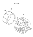
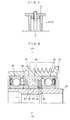
- Fig. 7 shows an example of the masking for a local cementation, which allows the cementation of only on the outer surface of the inner ring 10.
- An inner ring 10 is set around the peripheral of a supporting stay shaft C.
- a closing cover D is screwed with an end of the supporting stay shaft C so that both of the axial ends and the center hole of the inner ring 10 can be masked from the exterior, and only the outer surface of the inner ring 10 is exposed to the exterior.
- the hollow shaft 2 in the pulley unit A shown in Fig. 4 can be fabricated as follow.
- the material of the hollow shaft 2 shall be selected from a group of low carbon steel.
- the hollow shaft 2 shall be formed from a low carbon steel material by cold forging or drawing.
- the cementation of the outer surface of the hollow shaft 2 is preferable.
- a plurality of the cam surfaces 10a and orbital portions for the rollers can be simultaneously formed by plastic deformation of the outer surface of the hollow shaft 2.
- the plurality of can surfaces 10a and orbital portions are made one after another by lathe cutting.
- the working process for fabricating the cam surface 10a and the orbital portions for the rollers can be simplified in the present invention compared to the prior art. Therefore the productivity can be increased.
- a problem of the low wear resistance may arise, when a low carbon steel material is used.
- the wear resistance can, however, be increased by the cementation to harden the surface of the outer surface of the hollow shaft 2 after the cold elastic deformation. Using such a hollow shaft 2 having a high preciseness and formed inexpensively, it will be advantageous to lower the fabrication cost of the pulley unit A and to ameliorate the product quality.
- a local cementation of the outer surface of the hollow shaft 2 is preferable, due to the same reason as in the case of the inner ring 10. Therefore, a masked cementation of the hollow shaft 2, as shown in Fig. 7, is preferable.
Landscapes
- Engineering & Computer Science (AREA)
- General Engineering & Computer Science (AREA)
- Mechanical Engineering (AREA)
- Pulleys (AREA)
Abstract
Description
Claims (13)
- A pulley unit including:whereinan inner shaft;an outer ring disposed concentrically with said inner shaft;a one-way clutch having a plurality of rollers and disposed between the annular space between said inner shaft and said outer ring;two rolling bearings, which are fixed in said annular space at a side and at the other side of said one-way clutch;said one-way clutch comprises a cage, which constrain the moving region of the plurality of rollers; andthe inner radius of the cage is designed to be smaller than the outer radius of the orbital portion of the inner ring of a rolling bearing.
- The pulley unit according to claim 1 wherein the inner radius of said cage being designed to be smaller than the outer radius of the orbital portion of the inner ring of the other rolling bearing.
- A pulley unit according to claim 2 wherein said one-way clutch comprises an inner ring, an outer ring, a cage, a plurality of rollers and a plurality of coil springs;the inner ring of the one-way clutch is force fitted around the outer surface of said inner shaft, and has a plurality of flat key formed cam surfaces on its outer surface peripheral;the outer ring of the one-way clutch is force fitted into the inner surface of said outer ring, and the inner surface of the outer ring has a cylindrical form;the inner surface of the cage of the one-way clutch has a form corresponding to the cam surface of said inner ring of the one-way clutch, andthe cage, having an inner surface form corresponding to the cam surface of said inner ring, is disposed in the opposed annular space between said inner ring and said outer ring extends in the axial direction, is attached to the cam surface of the inner ring, and as well, is provided with pockets at each region corresponding to each of the cam surfaces of the inner ring of the one-way clutch, each of the pockets penetrate through the cage in the radial direction, and a projecting portion is disposed on the inner wall surface of each of the pockets;each of said plurality of the rollers of the one-way clutch is received in each of the pockets of said cage one by one, so that the rolling regions in the angular direction of the rollers are constrained; andsaid coil springs are disposed correspondingly to the projecting portion in each of said pockets so that the rollers are pushed to a confined wedge space between the cam surface and the inner surface of the outer ring.
- The pulley unit according to claim 3, wherein said outer ring is a pulley having an undulate groove for putting a V ribbed belt on its outer peripheral;said inner shaft is hollow shaft;on one hand, when the rotation velocity of said pulley is comparatively higher than that of said hollow shaft, the rollers of said one-way clutch rolls into the confined side of said wedge space so that a locking state takes place and said pulley and said hollow shaft aggregate to rotate with synchronism;on the other hand, when the rotation velocity of said pulley is comparatively slower than that of said hollow shaft, the rollers of said one-way clutch rolls into the wider side of said wedge space so that a free state takes place and the rotation power transmission from said pulley to said hollow shaft is cut off, and said hollow shaft continues to rotate only by its rotational inertia.
- The pulley unit according to claim 1, wherein the outer surface of said inner shaft in an axial center zone is an orbital portion of the inner ring of the one-way clutch;
and the outer surface of the inner shaft in an axial end zone is an orbital portion of said inner ring of one of the roller bearings. - The pulley unit according to claim 5, wherein the outer surface of said inner shaft in the other axial end zone is an orbital portion of said inner ring of the other of the roller bearings.
- The pulley unit according to claim 5, wherein the inner surface of said outer ring is formed to be circular;a plurality of flat cam surfaces are disposed on the orbital portion of the peripheral of said inner ring of said one-way clutch so that a wedge formed space is formed between the inner surface of said outer ring and said inner ring;the outer radius of the maximum radius portion of this cam surface are designed to be substantially identical to the outer radius of the orbital portion of said inner ring of one rolling bearing;the outer radius of the minimum radius portion of this cam surface are designed to be substantially identical to the outer radius of the orbital portion of the inner ring of said other rolling bearing;and the cage of said other rolling bearing is axially positioned with respect to the inner shaft.
- The pulley unit according to claim 7, wherein a peripheral groove is disposed on the outer surface of said inner shaft in the other zone;a radially inward directed projecting portion is disposed on the inner surface of the cage of said other rolling bearing;and said projecting portion engages into said peripheral groove so that the cage of said other rolling bearing is axially positioned.
- The pulley unit according to claim 7, wherein said one rolling bearing is deep grove type ball bearing and said other rolling bearing is a cage-and-roller type bearing;
the outer radii of each outer periphery of the inner shaft reduces stepwise in the axial direction from an end to the other end of the inner shaft. - The pulley unit according to claim 9, wherein a peripheral groove is disposed on the outer peripheral of said inner shaft in the other axial end zone;a radially inward directed projecting portion is disposed on the inner surface of the cage of said cage-and-roller bearing;and said projecting portion engages into said peripheral groove so that the cage of said cage-and-roller bearing is axially positioned.
- The pulley unit according to claim 10, wherein said inner surface of the outer ring forms the orbital portion of the outer ring of the one-way clutch as well as said outer rings of both the rolling bearings.
- The pulley unit according to claim 1, wherein said one-way clutch comprises an outer ring having a cylindrical inner surface, and an inner ring having a plurality of cam surfaces for forming a wedge formed space between the cylindrical inner surface of said outer ring and the cam surface, each of said rollers is disposed in each of the wedge space one by one and the rolling region of the rollers are constrained in the angular direction by said cage;
the inner ring of said one-way clutch is made from low carbon steel, and the outer form of the inner ring is formed by cold forging or elastic deformation process, then this outer surface is cemented so as to harden the surface. - The pulley unit according to claim 5, wherein the inner shaft is made from low carbon steel, and the outer form of the inner shaft is formed by cold forging or elastic deformation, then the outer surface is cemented so as to harden the surface.
Priority Applications (1)
| Application Number | Priority Date | Filing Date | Title |
|---|---|---|---|
| EP02018038A EP1256745B1 (en) | 1999-11-19 | 2000-11-15 | Pulley unit |
Applications Claiming Priority (4)
| Application Number | Priority Date | Filing Date | Title |
|---|---|---|---|
| JP32943199 | 1999-11-19 | ||
| JP32943099A JP3857478B2 (en) | 1999-11-19 | 1999-11-19 | Pulley unit |
| JP32943199 | 1999-11-19 | ||
| JP32943099 | 1999-11-19 |
Related Child Applications (2)
| Application Number | Title | Priority Date | Filing Date |
|---|---|---|---|
| EP02018038A Division EP1256745B1 (en) | 1999-11-19 | 2000-11-15 | Pulley unit |
| EP02018038.6 Division-Into | 2002-08-13 |
Publications (2)
| Publication Number | Publication Date |
|---|---|
| EP1101978A1 true EP1101978A1 (en) | 2001-05-23 |
| EP1101978B1 EP1101978B1 (en) | 2005-01-12 |
Family
ID=26573200
Family Applications (2)
| Application Number | Title | Priority Date | Filing Date |
|---|---|---|---|
| EP00124905A Expired - Lifetime EP1101978B1 (en) | 1999-11-19 | 2000-11-15 | Pulley unit with one-way clutch |
| EP02018038A Expired - Lifetime EP1256745B1 (en) | 1999-11-19 | 2000-11-15 | Pulley unit |
Family Applications After (1)
| Application Number | Title | Priority Date | Filing Date |
|---|---|---|---|
| EP02018038A Expired - Lifetime EP1256745B1 (en) | 1999-11-19 | 2000-11-15 | Pulley unit |
Country Status (3)
| Country | Link |
|---|---|
| US (2) | US6588560B1 (en) |
| EP (2) | EP1101978B1 (en) |
| DE (2) | DE60017339T2 (en) |
Cited By (9)
| Publication number | Priority date | Publication date | Assignee | Title |
|---|---|---|---|---|
| WO2003025433A1 (en) * | 2001-09-11 | 2003-03-27 | Nsk Ltd. | Pulley apparatus with built-in roller clutch and assembly method thereof |
| EP1300602A3 (en) * | 2001-10-02 | 2003-06-04 | Koyo Seiko Co., Ltd. | Pulley unit having one-way clutch |
| EP1316740A3 (en) * | 2001-11-29 | 2003-07-02 | Kabushiki Kaisha Toyota Jidoshokki | One way clutch assembly |
| EP1605189A3 (en) * | 2004-06-07 | 2009-04-01 | Denso Automotive Deutschland GmbH | Device for transmitting torque from a pulley to a shaft |
| CN105074255A (en) * | 2013-03-12 | 2015-11-18 | 株式会社捷太格特 | One-way clutch for wind power generation device, and wind power generation device |
| EP2886900A4 (en) * | 2012-08-20 | 2016-08-03 | Nsk Ltd | Roller clutch equipped with support bearing |
| US20160265515A1 (en) | 2013-10-28 | 2016-09-15 | Jtekt Corporation | Joint structure and wind power generation device |
| EP2985460A4 (en) * | 2013-03-12 | 2016-11-02 | Jtekt Corp | Shaft coupling device and wind power generation device |
| US10428801B2 (en) | 2013-03-12 | 2019-10-01 | Jtekt Corporation | Wind power generation device |
Families Citing this family (40)
| Publication number | Priority date | Publication date | Assignee | Title |
|---|---|---|---|---|
| US6588560B1 (en) * | 1999-11-19 | 2003-07-08 | Koyo Seiko Co., Ltd. | Pulley unit |
| US6749050B2 (en) * | 2000-07-03 | 2004-06-15 | Nsk Ltd. | One-way clutch built-in type pulley device |
| JP4161740B2 (en) * | 2003-02-28 | 2008-10-08 | 株式会社ジェイテクト | One-way clutch unit |
| US7364364B2 (en) * | 2003-09-23 | 2008-04-29 | Timken Us Corporation | Cartridge bearing |
| JP4487547B2 (en) * | 2003-12-05 | 2010-06-23 | 株式会社ジェイテクト | Cage, one-way clutch using the cage, and method for assembling the one-way clutch |
| KR100964891B1 (en) * | 2004-10-12 | 2010-06-23 | 주식회사 만도 | Ball screw units with ball nut steering |
| EP1947370A1 (en) * | 2005-10-14 | 2008-07-23 | JTEKT Corporation | Pulley apparatus and auto-tensioner |
| US20070267529A1 (en) * | 2006-04-12 | 2007-11-22 | Pure Fishing, Inc. | Clutch Assembly For A Fishing Reel |
| JP4905001B2 (en) * | 2006-09-05 | 2012-03-28 | 株式会社ジェイテクト | One-way clutch and power transmission device |
| DE202007011358U1 (en) * | 2007-08-14 | 2007-10-18 | Schaeffler Kg | Overrunning alternator pulley |
| DE102007039522B4 (en) * | 2007-08-21 | 2019-10-02 | Trützschler GmbH & Co Kommanditgesellschaft | Device on a drafting system of a range for textile fiber ribbons |
| DE102007039523B4 (en) * | 2007-08-21 | 2019-08-08 | Trützschler GmbH & Co Kommanditgesellschaft | Device on a track with a drafting system for textile fiber ribbons |
| US8944947B2 (en) * | 2008-03-26 | 2015-02-03 | Jtekt Corporation | Pulley unit |
| US8529387B2 (en) * | 2008-04-30 | 2013-09-10 | Dayco Ip Holdings, Llc | Pulley with asymmetric torque-sensitive clutching |
| US7931552B2 (en) * | 2008-04-30 | 2011-04-26 | Dayco Products, Llc | Pulley with torque-sensitive clutching |
| US8784244B2 (en) * | 2008-04-30 | 2014-07-22 | Dayco Ip Holdings, Llc | Pulley with asymmetric torque-sensitive clutching |
| US8257210B2 (en) | 2008-05-27 | 2012-09-04 | Jtekt Corporation | Rotation urging mechanism and pulley device |
| TWI473949B (en) * | 2009-09-04 | 2015-02-21 | Victory Ind Corp | Improvement of Unidirectional Pulley Structure of Vehicle Alternator |
| US8888627B2 (en) | 2010-05-25 | 2014-11-18 | Dayco Ip Holdings, Llc | One-way damped over-arm tensioner |
| WO2012139224A1 (en) * | 2011-04-11 | 2012-10-18 | Litens Automotive Partnership | Multi-speed drive for transferring power to a load |
| US9035476B2 (en) * | 2011-09-12 | 2015-05-19 | Jtekt Corporation | Power generating device |
| WO2013077422A1 (en) * | 2011-11-25 | 2013-05-30 | 日本精工株式会社 | Rotating machine with pulley and built-in one-way clutch |
| US8888622B2 (en) * | 2012-06-04 | 2014-11-18 | The Gates Corporation | Isolator decoupler |
| CA2876487A1 (en) * | 2012-06-20 | 2013-12-27 | Dayco Ip Holdings, Llc | Accessory drive decoupler |
| FR2993330B1 (en) * | 2012-07-13 | 2014-08-15 | Skf Ab | MECHANICAL SYSTEM WITH A UNIDIRECTIONAL CLUTCH AND ALTERNATOR COMPRISING SUCH A SYSTEM |
| ITTO20130677A1 (en) | 2013-08-06 | 2015-02-07 | Dayco Europe Srl | FILTERING PULLEY FOR A BELT DRIVE |
| FR3014157A1 (en) * | 2013-12-02 | 2015-06-05 | Skf Ab | DEBRAYABLE PULLEY DEVICE, ALTERNATOR COMPRISING SUCH A DEVICE AND INTERNAL COMBUSTION ENGINE EQUIPPED WITH SUCH A DEVICE OR SUCH ALTERNATOR |
| JP6256013B2 (en) * | 2014-01-09 | 2018-01-10 | 株式会社ジェイテクト | Pulley unit |
| US9476497B2 (en) * | 2014-04-23 | 2016-10-25 | Ningbo Yangtong Automobile Parts Co., Ltd | Unidirectional clutch decoupling device for transferring torque between belt wheel and shaft |
| TWI551795B (en) * | 2014-07-14 | 2016-10-01 | 勝利工業股份有限公司 | Pulley for an alternator |
| TWI555932B (en) * | 2014-07-14 | 2016-11-01 | 勝利工業股份有限公司 | Pulley for an alternator |
| US9291253B1 (en) | 2015-03-24 | 2016-03-22 | Gates Corporation | Isolating decoupler |
| JP2017110729A (en) * | 2015-12-16 | 2017-06-22 | 株式会社ジェイテクト | One-way clutch |
| DE102017127528B4 (en) * | 2017-05-10 | 2019-02-21 | Schaeffler Technologies AG & Co. KG | Freewheel unit and transmission device with the freewheel unit |
| US10514073B2 (en) * | 2017-08-30 | 2019-12-24 | Schaeffler Technologies AG & Co. KG | Bearing with integrated wedge locking assembly |
| US20190211912A1 (en) * | 2018-01-09 | 2019-07-11 | Alt America Inc. | Axial Driven Overrunning Alteration Pulleys |
| CN108843771B (en) * | 2018-07-18 | 2019-06-11 | 台州宝茨汽车零部件有限公司 | The isolator belt pulley for reducing resonant frequency is adjusted by axial motion |
| US11549558B2 (en) | 2018-08-01 | 2023-01-10 | Gates Corporation | Isolator decoupler |
| FR3090060B1 (en) * | 2018-12-18 | 2024-04-19 | Skf Svenska Kullagerfab Ab | Pulley device |
| US12098762B2 (en) * | 2022-09-16 | 2024-09-24 | Gates Corporation | Low axial runout driven pulley through the application of a spindle shaft utilizing multiple sets of bearings with radial clearance to the shaft |
Citations (12)
| Publication number | Priority date | Publication date | Assignee | Title |
|---|---|---|---|---|
| US4808082A (en) * | 1986-10-29 | 1989-02-28 | Bbc Brown Boveri Ag | Pressure wave supercharger |
| JPH06109021A (en) * | 1992-09-30 | 1994-04-19 | Ntn Corp | Rolling bearing |
| US5675202A (en) * | 1995-05-22 | 1997-10-07 | Mitsubishi Denki Kabushi Kaisha | Generator having pulley with one-way clutch |
| JPH1163170A (en) * | 1997-08-28 | 1999-03-05 | Nippon Seiko Kk | Pulley device with built-in roller clutch for alternator |
| GB2331134A (en) * | 1997-09-25 | 1999-05-12 | Koyo Seiko Co | A pulley unit with a one-way clutch having press-fitted roller bearings |
| FR2774446A1 (en) * | 1998-02-05 | 1999-08-06 | Koyo Seiko Co | Belt pulley unit for seat belt of vehicle |
| JPH11230314A (en) * | 1998-02-16 | 1999-08-27 | Koyo Seiko Co Ltd | Pulley unit |
| EP0947721A2 (en) * | 1998-04-02 | 1999-10-06 | Koyo Seiko Co., Ltd. | One-way clutch |
| JP2000227151A (en) * | 1999-02-05 | 2000-08-15 | Nsk Ltd | Pulley device with built-in one-way clutch for alternator |
| EP1028265A1 (en) * | 1999-02-12 | 2000-08-16 | Nsk Ltd | Roller clutch built-in type pulley apparatus for alternator |
| JP2001003961A (en) * | 1999-06-22 | 2001-01-09 | Koyo Seiko Co Ltd | One-way clutch and pulley unit therewith |
| EP1067303A2 (en) * | 1999-07-09 | 2001-01-10 | Nsk Ltd | Alternator pulley unit with a built-in one-way clutch |
Family Cites Families (22)
| Publication number | Priority date | Publication date | Assignee | Title |
|---|---|---|---|---|
| US1483512A (en) * | 1920-07-14 | 1924-02-12 | Automatic Telephone Mfg Co Ltd | Motor |
| US3017002A (en) * | 1957-07-05 | 1962-01-16 | Marland One Way Clutch Co | One-way clutch |
| US3734582A (en) * | 1971-10-29 | 1973-05-22 | Roulements Soc Nouvelle | Combination bearing materials |
| US3899225A (en) * | 1972-12-01 | 1975-08-12 | Torrington Co | Radial and thrust bearing |
| DE2758841C2 (en) * | 1977-12-30 | 1986-09-04 | Stieber Division Der Borg-Warner Gmbh, 6900 Heidelberg | Sprag overrunning clutch |
| DE2932290A1 (en) * | 1979-08-09 | 1981-02-26 | Skf Kugellagerfabriken Gmbh | ROLLER BEARING |
| DE3304641A1 (en) * | 1982-02-13 | 1983-09-15 | Hiroshi Teramachi | ROLLER BEARING LONGITUDINAL GUIDE FOR UNLIMITED SLIDING PATHS |
| IT8452936V0 (en) * | 1984-02-01 | 1984-02-01 | Riv Officine Di Villar Perosa | TRANSMISSION UNIT SUITABLE FOR TRANSMITTING THE MOTORCYCLE BY A DRIVE BELT FROM THE CRANKSHAFT OF A COMBUSTION ENGINE INTERNAL TO THE ENGINE ACCESSORIES |
| EP0559918B1 (en) * | 1991-09-30 | 1997-12-17 | Ntn Corporation | Torque limiter having automatic reset functions |
| JP3316307B2 (en) * | 1994-06-07 | 2002-08-19 | 日本トムソン株式会社 | Thrust bearing |
| DE9417045U1 (en) * | 1994-10-22 | 1994-12-15 | INA Wälzlager Schaeffler KG, 91074 Herzogenaurach | Device for damping torsional vibrations in a drive train |
| DE4442404C2 (en) * | 1994-11-30 | 1999-07-01 | Schaeffler Waelzlager Ohg | Anti-rotation device for a plastic cage of a freewheel |
| JPH0914301A (en) * | 1995-06-27 | 1997-01-14 | Ntn Corp | One-way clutch |
| DE19709479A1 (en) * | 1997-03-07 | 1998-09-10 | Torrington Nadellager Gmbh | Drive unit for automobile current generator |
| JP3556800B2 (en) * | 1997-04-09 | 2004-08-25 | 光洋精工株式会社 | Alternator pulley |
| US6170625B1 (en) * | 1997-07-01 | 2001-01-09 | Koyo Seiko Co., Ltd. | Pulley unit |
| JP3640771B2 (en) * | 1997-07-01 | 2005-04-20 | 光洋精工株式会社 | Pulley unit |
| JP3731702B2 (en) * | 1997-09-24 | 2006-01-05 | 光洋精工株式会社 | Pulley unit |
| JP3996991B2 (en) * | 1998-01-27 | 2007-10-24 | 株式会社ジェイテクト | One-way clutch |
| US6588560B1 (en) * | 1999-11-19 | 2003-07-08 | Koyo Seiko Co., Ltd. | Pulley unit |
| JP4244518B2 (en) * | 2000-07-27 | 2009-03-25 | 株式会社ジェイテクト | Pulley unit |
| US6830137B2 (en) * | 2001-05-24 | 2004-12-14 | Koyo Seiko Co., Ltd. | Pulley unit having one-way clutch |
-
2000
- 2000-11-13 US US09/711,800 patent/US6588560B1/en not_active Expired - Lifetime
- 2000-11-15 DE DE60017339T patent/DE60017339T2/en not_active Expired - Lifetime
- 2000-11-15 DE DE60036567T patent/DE60036567T2/en not_active Expired - Lifetime
- 2000-11-15 EP EP00124905A patent/EP1101978B1/en not_active Expired - Lifetime
- 2000-11-15 EP EP02018038A patent/EP1256745B1/en not_active Expired - Lifetime
-
2002
- 2002-07-12 US US10/193,928 patent/US7004861B2/en not_active Expired - Lifetime
Patent Citations (12)
| Publication number | Priority date | Publication date | Assignee | Title |
|---|---|---|---|---|
| US4808082A (en) * | 1986-10-29 | 1989-02-28 | Bbc Brown Boveri Ag | Pressure wave supercharger |
| JPH06109021A (en) * | 1992-09-30 | 1994-04-19 | Ntn Corp | Rolling bearing |
| US5675202A (en) * | 1995-05-22 | 1997-10-07 | Mitsubishi Denki Kabushi Kaisha | Generator having pulley with one-way clutch |
| JPH1163170A (en) * | 1997-08-28 | 1999-03-05 | Nippon Seiko Kk | Pulley device with built-in roller clutch for alternator |
| GB2331134A (en) * | 1997-09-25 | 1999-05-12 | Koyo Seiko Co | A pulley unit with a one-way clutch having press-fitted roller bearings |
| FR2774446A1 (en) * | 1998-02-05 | 1999-08-06 | Koyo Seiko Co | Belt pulley unit for seat belt of vehicle |
| JPH11230314A (en) * | 1998-02-16 | 1999-08-27 | Koyo Seiko Co Ltd | Pulley unit |
| EP0947721A2 (en) * | 1998-04-02 | 1999-10-06 | Koyo Seiko Co., Ltd. | One-way clutch |
| JP2000227151A (en) * | 1999-02-05 | 2000-08-15 | Nsk Ltd | Pulley device with built-in one-way clutch for alternator |
| EP1028265A1 (en) * | 1999-02-12 | 2000-08-16 | Nsk Ltd | Roller clutch built-in type pulley apparatus for alternator |
| JP2001003961A (en) * | 1999-06-22 | 2001-01-09 | Koyo Seiko Co Ltd | One-way clutch and pulley unit therewith |
| EP1067303A2 (en) * | 1999-07-09 | 2001-01-10 | Nsk Ltd | Alternator pulley unit with a built-in one-way clutch |
Non-Patent Citations (4)
| Title |
|---|
| DATABASE WPI Section PQ Week 200053, Derwent World Patents Index; Class Q63, AN 2000-570042, XP002162021 * |
| PATENT ABSTRACTS OF JAPAN vol. 018, no. 393 (M - 1643) 22 July 1994 (1994-07-22) * |
| PATENT ABSTRACTS OF JAPAN vol. 1999, no. 08 30 June 1999 (1999-06-30) * |
| PATENT ABSTRACTS OF JAPAN vol. 1999, no. 13 30 November 1999 (1999-11-30) * |
Cited By (15)
| Publication number | Priority date | Publication date | Assignee | Title |
|---|---|---|---|---|
| WO2003025433A1 (en) * | 2001-09-11 | 2003-03-27 | Nsk Ltd. | Pulley apparatus with built-in roller clutch and assembly method thereof |
| CN1307378C (en) * | 2001-09-11 | 2007-03-28 | 日本精工株式会社 | Pulley device with embedded roller clutch and assembly method thereof |
| US6880689B2 (en) | 2001-09-11 | 2005-04-19 | Nsk Ltd. | Pulley apparatus with built-in roller clutch and assembly method thereof |
| EP1457699A3 (en) * | 2001-10-02 | 2004-09-22 | Koyo Seiko Co., Ltd. | Pulley unit having one-way clutch |
| US7143881B2 (en) | 2001-10-02 | 2006-12-05 | Koyo Seiko Co., Ltd. | Pulley unit having one-way clutch |
| EP1300602A3 (en) * | 2001-10-02 | 2003-06-04 | Koyo Seiko Co., Ltd. | Pulley unit having one-way clutch |
| EP1316740A3 (en) * | 2001-11-29 | 2003-07-02 | Kabushiki Kaisha Toyota Jidoshokki | One way clutch assembly |
| EP1605189A3 (en) * | 2004-06-07 | 2009-04-01 | Denso Automotive Deutschland GmbH | Device for transmitting torque from a pulley to a shaft |
| EP2886900A4 (en) * | 2012-08-20 | 2016-08-03 | Nsk Ltd | Roller clutch equipped with support bearing |
| CN105074255A (en) * | 2013-03-12 | 2015-11-18 | 株式会社捷太格特 | One-way clutch for wind power generation device, and wind power generation device |
| EP2985460A4 (en) * | 2013-03-12 | 2016-11-02 | Jtekt Corp | Shaft coupling device and wind power generation device |
| CN105074255B (en) * | 2013-03-12 | 2018-02-27 | 株式会社捷太格特 | One-way clutch and wind power plant for wind power plant |
| US10428801B2 (en) | 2013-03-12 | 2019-10-01 | Jtekt Corporation | Wind power generation device |
| US20160265515A1 (en) | 2013-10-28 | 2016-09-15 | Jtekt Corporation | Joint structure and wind power generation device |
| US10495066B2 (en) | 2013-10-28 | 2019-12-03 | Jtekt Corporation | Joint structure and wind power generation device |
Also Published As
| Publication number | Publication date |
|---|---|
| DE60017339T2 (en) | 2005-12-22 |
| EP1256745A2 (en) | 2002-11-13 |
| US7004861B2 (en) | 2006-02-28 |
| EP1101978B1 (en) | 2005-01-12 |
| EP1256745B1 (en) | 2007-09-26 |
| DE60017339D1 (en) | 2005-02-17 |
| DE60036567T2 (en) | 2008-06-19 |
| US6588560B1 (en) | 2003-07-08 |
| EP1256745A3 (en) | 2004-04-21 |
| US20020183147A1 (en) | 2002-12-05 |
| DE60036567D1 (en) | 2007-11-08 |
Similar Documents
| Publication | Publication Date | Title |
|---|---|---|
| EP1101978B1 (en) | Pulley unit with one-way clutch | |
| EP1262686B1 (en) | Pulley unit having one-way clutch | |
| EP0947721A2 (en) | One-way clutch | |
| US6655516B2 (en) | Concentrically arranged pulley and shaft with one-way clutch | |
| JP3785259B2 (en) | Pulley unit | |
| JPH1182688A (en) | Pulley unit | |
| JP2003074672A (en) | Pulley unit | |
| JP2002039221A (en) | One-way clutch | |
| JP3857478B2 (en) | Pulley unit | |
| JP3740443B2 (en) | Pulley unit | |
| JP3640771B2 (en) | Pulley unit | |
| JP2001349346A (en) | One-way clutch and pulley unit having the clutch | |
| JP2002349677A (en) | Roller clutch and rotation transmission device with built-in roller clutch | |
| JP2003004121A (en) | Pulley unit | |
| JP4140152B2 (en) | One-way clutch | |
| JPH11230314A (en) | Pulley unit | |
| JPH1130312A (en) | Pulley unit | |
| JP2001090810A (en) | Pulley unit and one-way clutch used therefor | |
| JP2001003961A (en) | One-way clutch and pulley unit therewith | |
| JP4461835B2 (en) | Pulley unit | |
| JPH11280873A (en) | Pulley | |
| JP4893997B2 (en) | One-way clutch | |
| JP2001140943A (en) | One-way clutch | |
| JPH11270658A (en) | Pulley unit | |
| JPH11280872A (en) | Pulley unit |
Legal Events
| Date | Code | Title | Description |
|---|---|---|---|
| PUAI | Public reference made under article 153(3) epc to a published international application that has entered the european phase |
Free format text: ORIGINAL CODE: 0009012 |
|
| AK | Designated contracting states |
Kind code of ref document: A1 Designated state(s): DE FR GB IT |
|
| AX | Request for extension of the european patent |
Free format text: AL;LT;LV;MK;RO;SI |
|
| 17P | Request for examination filed |
Effective date: 20010816 |
|
| AKX | Designation fees paid |
Free format text: DE FR GB IT |
|
| 17Q | First examination report despatched |
Effective date: 20020902 |
|
| GRAP | Despatch of communication of intention to grant a patent |
Free format text: ORIGINAL CODE: EPIDOSNIGR1 |
|
| GRAS | Grant fee paid |
Free format text: ORIGINAL CODE: EPIDOSNIGR3 |
|
| GRAA | (expected) grant |
Free format text: ORIGINAL CODE: 0009210 |
|
| AK | Designated contracting states |
Kind code of ref document: B1 Designated state(s): DE FR GB IT |
|
| REG | Reference to a national code |
Ref country code: GB Ref legal event code: FG4D |
|
| REF | Corresponds to: |
Ref document number: 60017339 Country of ref document: DE Date of ref document: 20050217 Kind code of ref document: P |
|
| PLBE | No opposition filed within time limit |
Free format text: ORIGINAL CODE: 0009261 |
|
| STAA | Information on the status of an ep patent application or granted ep patent |
Free format text: STATUS: NO OPPOSITION FILED WITHIN TIME LIMIT |
|
| ET | Fr: translation filed | ||
| 26N | No opposition filed |
Effective date: 20051013 |
|
| PGFP | Annual fee paid to national office [announced via postgrant information from national office to epo] |
Ref country code: FR Payment date: 20141110 Year of fee payment: 15 |
|
| PGFP | Annual fee paid to national office [announced via postgrant information from national office to epo] |
Ref country code: GB Payment date: 20151111 Year of fee payment: 16 Ref country code: IT Payment date: 20151124 Year of fee payment: 16 |
|
| REG | Reference to a national code |
Ref country code: FR Ref legal event code: ST Effective date: 20160729 |
|
| PG25 | Lapsed in a contracting state [announced via postgrant information from national office to epo] |
Ref country code: FR Free format text: LAPSE BECAUSE OF NON-PAYMENT OF DUE FEES Effective date: 20151130 |
|
| GBPC | Gb: european patent ceased through non-payment of renewal fee |
Effective date: 20161115 |
|
| PG25 | Lapsed in a contracting state [announced via postgrant information from national office to epo] |
Ref country code: IT Free format text: LAPSE BECAUSE OF NON-PAYMENT OF DUE FEES Effective date: 20161115 |
|
| PG25 | Lapsed in a contracting state [announced via postgrant information from national office to epo] |
Ref country code: GB Free format text: LAPSE BECAUSE OF NON-PAYMENT OF DUE FEES Effective date: 20161115 |
|
| PGFP | Annual fee paid to national office [announced via postgrant information from national office to epo] |
Ref country code: DE Payment date: 20181030 Year of fee payment: 19 |
|
| REG | Reference to a national code |
Ref country code: DE Ref legal event code: R119 Ref document number: 60017339 Country of ref document: DE |
|
| PG25 | Lapsed in a contracting state [announced via postgrant information from national office to epo] |
Ref country code: DE Free format text: LAPSE BECAUSE OF NON-PAYMENT OF DUE FEES Effective date: 20200603 |