JP3640771B2 - Pulley unit - Google Patents
Pulley unit Download PDFInfo
- Publication number
- JP3640771B2 JP3640771B2 JP17577597A JP17577597A JP3640771B2 JP 3640771 B2 JP3640771 B2 JP 3640771B2 JP 17577597 A JP17577597 A JP 17577597A JP 17577597 A JP17577597 A JP 17577597A JP 3640771 B2 JP3640771 B2 JP 3640771B2
- Authority
- JP
- Japan
- Prior art keywords
- way clutch
- inner ring
- cage
- pulley unit
- axial direction
- Prior art date
- Legal status (The legal status is an assumption and is not a legal conclusion. Google has not performed a legal analysis and makes no representation as to the accuracy of the status listed.)
- Expired - Fee Related
Links
Images


Description
【0001】
【発明の属する技術分野】
本発明は、一方向クラッチを備えるプーリユニットに関する。このプーリユニットは、例えば自動車などのエンジンのクランクシャフトからベルトを介して駆動される補機に装備することができる。補機としては、例えば自動車のエアコンディショナ用コンプレッサ、ウォーターポンプ、オルターネータ、冷却ファンなどが挙げられる。
【0002】
【従来の技術】
自動車エンジンに装着される各種の補機は、エンジンのクランクシャフトによりベルトを介して駆動されるようになっている。ここで、補機のうち、特にオルタネータの場合、エンジンのクランクシャフトと同期回転するように連結していると、クランクシャフトの回転数が低下するとき、オルタネータの発電能力が低下する。
【0003】
そこで、本願出願人は、オルタネータに上記一方向クラッチを内蔵し、クランクシャフトの回転数が低下するときに、オルタネータのロータの回転をその慣性力により継続させるようにして、発電効率を高めることを考えている。
【0004】
この場合、オルタネータのプーリとロータとの間に一方向クラッチを介装し、プーリとロータとの回転差に応じて、一方向クラッチをフリー状態(動力伝達状態)とロック状態(動力伝達遮断状態)とに切り替え、プーリとロータとの間で動力伝達させたり遮断させたりするようにする。
【0005】
上述した一方向クラッチは、もともと、ロック、フリー動作を行わせるために、カム面が形成される部材に対して保持器を回り止めさせる必要がある。この保持器の回り止め対策として、本願出願人は、実願平5−5162号に添付の明細書に示すような構成を考えている。つまり、外輪の円周数カ所に形成してある凹状カム面を軸方向一端にまで延ばし、保持器の軸方向一端で外周面の円周数カ所に前記凹状カム面に係入する凸部を設け、凹状カム面に対する凸部の周方向での引っ掛かりにより、外輪に対し保持器を回り止めさせる。
【0006】
【発明が解決しようとする課題】
上記従来の一方向クラッチでは、外輪に形成している既存の凹状カム面を流用して保持器の回り止めを行わせる構造としているので、下記するような不具合が発生している。
【0007】
そもそも、既存の凹状カム面の断面形状は、円弧のように一定の曲率半径になっていない。そして、保持器の回り止めだけのために、前記凸部の断面形状を前述の凹状カム面に対応させて高精度に加工するのは、コストの点からして無駄であると考え、従来では、凹状カム面に対して凸部を単に係入させるだけに設定している。このような構造では、一方向クラッチのロック、フリー動作時に、ころ付勢用の弾性部材の反力により保持器が周方向にぐらつきやすくなってしまい、それによって、ロック、フリー動作時の応答性が悪くなる他、甚だしい場合には完全なロック状態にならなくなることも起こりうる。また、外側環体や内側環体の回転動作に伴い振動が継続して発生するような状況では、保持器が軸方向へ変位することがあり、ころがスキューしやすくなるなど、ロック、フリー動作が不安定になりやすくなることが指摘される。
【0008】
したがって、本発明は、一方向クラッチを備えるプーリユニットにおいて、一方向クラッチの保持器を周方向ならびに軸方向で不動とし、動作安定化を図ることを目的としている。
【0009】
【課題を解決するための手段】
本発明の第1のプーリユニットは、ベルトにより回転駆動される外側環体と、外側環体の内周に配設される内側環体と、両環体の間の環状空間に介装される一方向クラッチと、前記環状空間において一方向クラッチの両側に設けられる転がり軸受とを含むプーリユニットであって、一方向クラッチは、複数のころと、複数のころを収納するポケットを有する保持器と、保持器の外周に配設される外輪と、保持器のポケットに対応する位置にくさび状空間形成用のカム面が設けられている内輪と、ころをくさび状空間の狭い側へ押圧する弾性部材とを含み、前記内輪の軸方向一端面に軸端へ向けて開放する凹部が、また、前記保持器の軸方向一端内周側に前記凹部に軸方向から嵌合される凸部が、それぞれ設けられており、前記凹部の開口側に前記両転がり軸受のうち一方の転がり軸受の内輪が配設されて、前記凸部が凹部奥壁面と前記一方の転がり軸受の内輪端面とで挟まれる。
本発明の第2のプーリユニットは、第1のプーリユニットにおいて、前記両転がり軸受のそれぞれ軸方向外端のみに、密封部材が設けられている。
【0010】
プーリユニットは、同心状に配設される内外2つの環体と、両環体の間の環状空間に介装される一方向クラッチと、前記環状空間において一方向クラッチの両側に設けられる転がり軸受とを含むもので、一方向クラッチが、内・外輪、ころならびに保持器を含み、内・外輪のうちくさび状空間形成用のカム面が形成される側の軸方向一端面に、軸端へ向けて開放する凹部が、また、保持器の軸方向一端に、前記凹部に軸方向から嵌合される凸部が、それぞれ設けられており、前記凹部の開口側に前記両転がり軸受のうち一方の転がり軸受が配設されて、前記凸部が凹部奥壁面と前記一方の転がり軸受の内輪・外輪のうち前記カム面が形成される側の端面とで挟まれてもよい。
【0014】
以上、本発明のプーリユニットでは、外側環体と内側環体との回転差に応じて、一方向クラッチがロック状態とフリー状態とに切り替わって、外側環体と内側環体との間で動力を伝達したり遮断したりするようになっている。
【0015】
そして、カム面が形成される一方向クラッチの内輪に設けた凹部と、一方向クラッチの保持器に設けた凸部との軸方向からの嵌合により保持器の周方向の動きを封じている。また、凹部からの凸部の抜け出しを物理的に封じることにより、保持器の軸方向の動きを封じている。このように保持器を周方向ならびに軸方向に不動としているから、一方向クラッチのロック、フリー動作時に、ころ付勢用の弾性部材の反力により保持器が周方向にぐらつくことがなくなる他、振動や衝撃が加わる状況でもころがスキューしにくくなるなど、一方向クラッチのロック、フリー動作が安定的に行えるようになる。
【0016】
特に、本発明の第1のプーリユニットでは、一方向クラッチのカム面を内輪に設けているので、高速回転域でも遠心力によってころがロック位置から不必要に外れるのを防止できるようになる。
【0018】
さらに、第2のプーリユニットでは、一方向クラッチがその軸方向両側の転がり軸受によって密封されることになり、この一方向クラッチと両側の転がり軸受とを共通の潤滑剤によって潤滑することが可能となる。
【0019】
【発明の実施の形態】
本発明の詳細を図1ないし図5に示す実施形態に基づいて説明する。
【0020】
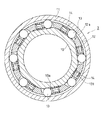
図1ないし図4は本発明の一実施形態にかかり、図1は、プーリユニットの縦断面図、図2は、図1の(2)−(2)線断面の矢視図、図3は、図1の(3)−(3)線断面の矢視図、図4は、一方向クラッチの一部を示す平面展開図である。
【0021】
図例のプーリユニットAは、同心状に配設される内外2つの環体1,2と、両環体1,2の間の環状空間に介装される一方向クラッチ3と、前記環状空間において一方向クラッチ3の軸方向両側に配設される2つの転がり軸受4,4とを備えている。
【0022】
外側環体1の外周には、波状のベルト巻き掛け用の溝が形成されており、この外側環体1は、例えば自動車エンジンのクランクシャフトによりいわゆるVベルトと呼ばれるベルトBを介して回転駆動されるようになっている。内側環体2は、スリーブ状の部材からなり、図示しないが自動車の補機の入力軸(例えばオルタネータのロータ)に固定される。
【0023】
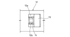
一方向クラッチ3は、外周面の円周数箇所に平坦なキー状のカム面10aが設けられた内輪10と、両端に転がり軸受4,4が内嵌されるように軸方向長尺に形成された外輪11と、カム面10aに対応して径方向内外に貫通形成されるポケット12aを有する保持器12と、保持器12の各ポケット12aに1つずつ収納される複数のころ13と、保持器12の各ポケット12aに1つずつ収納されかつころ13をカム面10aと外輪11内周面との間のくさび状空間の狭い側(ロック側)へ押圧する弾性部材としての断面ほぼ長方形のコイルバネ14とを備えている。保持器12のポケット12aの内壁面には、根元がくびれた形状の突起12bが一体形成されており、この突起12bの根元のくびれ部分にコイルバネ14の軸方向一端が係止嵌合され、突起12bの外周でコイルバネ14の内周を受けることにより、コイルバネ14の圧縮時のゆがみなどを防止するようになっている。なお、突起12bの先端外径面には、コイルバネ14の装着を容易とするためのテーパ面が設けられている。
【0024】
2つの転がり軸受4,4は、いずれも、内輪16、外輪17、複数の玉18、保持器19を有する一般的な深溝型玉軸受からなり、内・外輪16,17間の軸方向外端側にのみ密封部材としてのオイルシール20が装着されている。つまり、2つの転がり軸受4,4で一方向クラッチ3を密封するようになっていて、2つの転がり軸受4,4と一方向クラッチ3とを共通の潤滑剤で潤滑させるようにしている。
【0025】
次に、上述したプーリユニットAの特徴構成について説明する。この特徴構成とは、主として、一方向クラッチ3の保持器12を周方向ならびに軸方向に不動としていることである。具体的には、一方向クラッチ3の内輪10の軸方向一端面には、軸端へ向けて開放するとともに径方向内外に開放するスリット状の凹部10bが、また、保持器12の軸方向一端内周側には、凹部10bに軸方向から圧入嵌合される凸部12cが、それぞれ設けられており、これら凹部10bと凸部12cとの圧入嵌合により保持器12の周方向への動きを封じている。また、凸部12cは、凹部10bの奥壁面と、凹部10bの開口側に配設される片方の転がり軸受4の内輪16の端面とで軸方向から挟まれており、これにより保持器12の軸方向への動きを封じている。
【0026】
なお、凹部10bと凸部12cは、この実施形態において180度対向する2カ所に設けられている。この数は最低1カ所でもあるいは2カ所以上でもよい。但し、数を少なくすれば、加工精度をあまりシビアに管理せずに済む点で有利である。
【0027】
このように、一方向クラッチ3の保持器12の周方向ならびに軸方向の動きを封じているから、一方向クラッチ3のロック、フリー動作が安定的に行えるようになる。つまり、保持器12が周方向に不動であれば、コイルバネ14によるころ13の弾発付勢力の反力をしっかり受け止めることができるので、ころ13のロック動作を効率よくサポートできるようになる。また、保持器12が軸方向に不動であれば、ベルトBなどから振動や衝撃が加わる状況でもころ13がスキューしにくくなる。これらのことから、ころ13のロック、フリー動作が安定的に行われることになる。
【0028】
以上説明したプーリユニットAの動作を説明する。要するに、外側環体1の回転速度が内側環体2よりも相対的に速くなると、一方向クラッチ3のころ13がくさび状空間の狭い側へ転動させられてロック状態となるので、外側環体1と内側環体2とが一体化して同期回転する。しかし、外側環体1の回転速度が内側環体2よりも相対的に遅くなると、一方向クラッチ3のころ13がくさび状空間の広い側へ転動させられてフリー状態となるので、外側環体1から内側環体2へ回転動力の伝達が遮断されることになって内側環体2が回転慣性力のみで回転を継続するようになる。
【0029】
このようなプーリユニットAを仮にオルタネータに利用する場合だと、ベルトBの駆動源となるエンジンのクランクシャフトの回転変動に関係なく、オルタネータのロータの回転を高域に維持して、発電効率を高めるようにすることができる。つまり、クランクシャフトの回転数が上昇するとき、一方向クラッチ3がロック状態となって内側環体2を外側環体1と同期回転させるようにし、一方、クランクシャフトの回転数が低下するとき、一方向クラッチ3がフリー状態となって内側環体2を外側環体1の減速と無関係に自身の回転慣性力により回転継続させるようにすればよい。
【0030】
なお、本発明は上記実施例のみに限定されるものではなく、種々な応用や変形が考えられる。
【0031】
(1) 上記実施形態では、一方向クラッチ3の内輪10の軸方向一端面に径方向内外に連続するスリット状の凹部10bを設けているが、図5に示すように、凹部10bを平坦なキー状とすることができる。図5では、ころ13の使用数を多くするために、一方向クラッチ3の内輪10のカム面10aの周方向幅を狭くするとともに、カム面10aを曲線を含む形状としている。この曲線を含む部分がころ13のフリー回転位置となる。
【0032】
(2) 上記実施形態では、一方向クラッチ3の弾性部材としてコイルバネ14を例に挙げているが、それについても種々な板ばねや弾性片などで代用することができる。
【0033】
(3) 上記実施形態では、一方向クラッチ3のカム面10aを内輪側に形成した例を挙げているが、外輪側に設けたものにも本発明を適用できる。但し、上記実施形態の場合では、高速回転域でも遠心力によってころがロック位置から不必要に外れるのを防止できるなど、高速回転での使用に適している。
【0034】
【発明の効果】
請求項1または2の発明では、一方向クラッチの保持器を周方向ならびに軸方向に不動としているから、一方向クラッチのロック、フリー動作時に、ころ付勢用の弾性部材の反力により保持器が周方向にぐらつくことがなくなる他、振動や衝撃などが加わる状況でもころがスキューしにくくなるなど、一方向クラッチのロック、フリー動作を安定的に行わせることができる。
【0035】
特に、請求項1の発明では、一方向クラッチのカム面を内輪に設けているので、高速回転域でも遠心力によってころがロック位置から不必要に外れるのを防止できるようになる。したがって、この効果と上記保持器の動き拘束による効果との相乗により、ころの動作安定化を一層高めることができるようになる。
【0037】
さらに、請求項2の発明では、一方向クラッチがその軸方向両側の転がり軸受によって密封されることになり、この一方向クラッチと両側の転がり軸受とを共通の潤滑剤によって潤滑することが可能となる。
【0038】
このように、本発明によれば、一方向クラッチの動作を安定化して、同心状に配設される内外2つの環体間の動力伝達効率を高めることができるなど、信頼性の向上に貢献できる。
【図面の簡単な説明】
【図1】本発明の一実施形態のプーリユニットの縦断面図
【図2】図1の(2)−(2)線断面の矢視図
【図3】図1の(3)−(3)線断面の矢視図
【図4】一方向クラッチの一部を示す平面展開図
【図5】本発明の他の実施形態で、図3に対応する図
【符号の説明】
A プーリユニット
B ベルト
1 外側環体
2 内側環体
3 一方向クラッチ
4 転がり軸受
10 一方向クラッチの内輪
10a 内輪のカム面
10b 内輪の凹部
11 一方向クラッチの外輪
12 一方向クラッチの保持器
12a 保持器のポケット
12c 保持器の凸部
13 ころ
14 コイルバネ[0001]
BACKGROUND OF THE INVENTION
The present invention relates to a pulley unit including a one-way clutch. This pulley unit can be mounted on an auxiliary machine driven via a belt from a crankshaft of an engine such as an automobile. Examples of the auxiliary machine include a compressor for an air conditioner of a car, a water pump, an alternator, and a cooling fan.
[0002]
[Prior art]
Various auxiliary machines mounted on an automobile engine are driven via a belt by a crankshaft of the engine. Here, in the case of an alternator, in particular, in the case of an auxiliary machine, if it is connected so as to rotate synchronously with the crankshaft of the engine, when the number of rotations of the crankshaft decreases, the power generation capacity of the alternator decreases.
[0003]
Therefore, the applicant of the present application incorporates the above-described one-way clutch in the alternator, and when the rotational speed of the crankshaft decreases, the rotation of the alternator rotor is continued by its inertial force to increase the power generation efficiency. thinking.
[0004]
In this case, a one-way clutch is interposed between the pulley of the alternator and the rotor, and the one-way clutch is in a free state (power transmission state) and a locked state (power transmission cut-off state) according to the rotational difference between the pulley and the rotor. ) To transmit power between the pulley and the rotor.
[0005]
The one-way clutch described above originally needs to prevent the retainer from rotating with respect to the member on which the cam surface is formed in order to perform the lock and free operations. As a countermeasure against the rotation of the cage, the applicant of the present application considers a configuration as shown in the specification attached to the actual application No. 5-5162. That is, the concave cam surface formed at several places on the circumference of the outer ring extends to one end in the axial direction, and at one end in the axial direction of the cage, a convex portion that engages with the concave cam surface is provided at several places on the circumference of the outer circumference. The retainer is prevented from rotating with respect to the outer ring by being caught in the circumferential direction of the convex portion with respect to the concave cam surface.
[0006]
[Problems to be solved by the invention]
The conventional one-way clutch has a structure in which the existing concave cam surface formed on the outer ring is diverted to prevent the cage from rotating, and the following problems occur.
[0007]
In the first place, the cross-sectional shape of the existing concave cam surface is not a constant radius of curvature like an arc. And, in order to prevent only the retainer from rotating, it is considered wasteful in terms of cost to process the cross-sectional shape of the convex portion with high accuracy by corresponding to the concave cam surface described above. The convex portion is set to merely engage the concave cam surface. In such a structure, when the one-way clutch is locked or free, the cage is likely to wobble in the circumferential direction due to the reaction force of the elastic member for urging the rollers, and as a result, the responsiveness at the time of locking and free operation is achieved. In addition to being worse, it may happen that it is not fully locked in severe cases. Also, in situations where vibration continues to occur as the outer ring or inner ring rotates, the cage may be displaced in the axial direction, making it easier for the rollers to skew, locking and free operation It is pointed out that is likely to become unstable.
[0008]
Accordingly, an object of the present invention is to stabilize the operation of a pulley unit including a one-way clutch by making the cage of the one-way clutch immovable in the circumferential direction and the axial direction.
[0009]
[Means for Solving the Problems]
The first pulley unit of the present invention is interposed in an outer ring that is rotationally driven by a belt, an inner ring disposed on the inner periphery of the outer ring, and an annular space between both rings. A pulley unit including a one-way clutch and rolling bearings provided on both sides of the one-way clutch in the annular space, wherein the one-way clutch includes a plurality of rollers and a cage having a pocket for storing the plurality of rollers. An outer ring disposed on the outer periphery of the cage, an inner ring provided with a cam surface for forming a wedge-shaped space at a position corresponding to the pocket of the cage, and an elasticity for pressing the roller toward the narrow side of the wedge-shaped space and a member, the recess opening towards the shaft end in the axial end face of the inner ring, but also, the convex portion to be fitted in the axial direction in the axial direction end in the peripheral side in the concave portion of said retainer, Provided on the opening side of the recess. Serial is inner ring disposed on one of the rolling bearing of the rolling bearings, the convex portion is sandwiched between the inner race end surface of the one rolling bearing and the recess inner wall surface.
According to a second pulley unit of the present invention, in the first pulley unit, a sealing member is provided only at each axial end of each of the rolling bearings.
[0010]
Pulleys unit includes inner and outer two annulus disposed concentrically, and a one-way clutch interposed in an annular space between the two ring bodies, the rolling is provided on both sides of the one-way clutch in said annular space The one-way clutch includes inner and outer rings, rollers, and cages, and the end of the shaft is formed on one end surface in the axial direction on the side where the cam surface for forming the wedge-shaped space is formed. A concave portion that is open toward the concave portion, and a convex portion that is fitted into the concave portion from the axial direction is provided at one end of the cage in the axial direction, and the two rolling bearings are provided on the opening side of the concave portion. One rolling bearing may be provided, and the convex portion may be sandwiched between the inner wall surface of the concave portion and the end surface on the side where the cam surface is formed, of the inner ring and the outer ring of the one rolling bearing.
[0014]
As described above, in the pulley unit of the present invention, the one-way clutch is switched between the locked state and the free state in accordance with the rotation difference between the outer ring and the inner ring, and the power is generated between the outer ring and the inner ring. Is to transmit or block.
[0015]
And the movement of the circumferential direction of a cage | basket is sealed by fitting from the axial direction with the recessed part provided in the inner ring | wheel of the one-way clutch in which a cam surface is formed, and the convex part provided in the holder | retainer of the one-way clutch. . In addition, the movement of the cage in the axial direction is sealed by physically sealing the protruding portion from the recessed portion. Since the cage is fixed in the circumferential direction and the axial direction in this way, the cage does not wobble in the circumferential direction due to the reaction force of the elastic member for roller urging at the time of locking and free operation of the one-way clutch, The one-way clutch can be locked and freed stably, such as the roller is less likely to skew even under conditions of vibration and impact.
[0016]
In particular, in the first pulley unit of the present invention, since the cam surface of the one-way clutch is provided on the inner ring, it is possible to prevent the roller from being unnecessarily removed from the locked position by centrifugal force even in a high-speed rotation region.
[0018]
Further, in the second pulley unit, the one-way clutch is sealed by the rolling bearings on both sides in the axial direction, and the one-way clutch and the rolling bearings on both sides can be lubricated with a common lubricant. Become.
[0019]
DETAILED DESCRIPTION OF THE INVENTION
The details of the present invention will be described based on the embodiment shown in FIGS.
[0020]
1 to 4 relate to one embodiment of the present invention, FIG. 1 is a longitudinal sectional view of a pulley unit, FIG. 2 is a sectional view taken along line (2)-(2) in FIG. 1, and FIG. FIG. 4 is a sectional view taken along line (3)-(3) in FIG. 1, and FIG. 4 is a plan development view showing a part of the one-way clutch.
[0021]
The illustrated pulley unit A includes two inner and
[0022]
A wave-shaped belt winding groove is formed on the outer periphery of the
[0023]
The one-
[0024]
Each of the two rolling bearings 4 and 4 includes a general deep groove type ball bearing having an
[0025]
Next, the characteristic configuration of the pulley unit A described above will be described. This characteristic configuration is mainly that the
[0026]
In addition, the recessed
[0027]
Thus, since the movement in the circumferential direction and the axial direction of the
[0028]
The operation of the pulley unit A described above will be described. In short, when the rotational speed of the
[0029]
If such a pulley unit A is used for an alternator, the rotation of the alternator rotor is maintained at a high frequency regardless of the rotational fluctuation of the crankshaft of the engine that is the driving source of the belt B, thereby improving the power generation efficiency. Can be increased. That is, when the rotation speed of the crankshaft increases, the one-
[0030]
In addition, this invention is not limited only to the said Example, Various application and deformation | transformation can be considered.
[0031]
(1) In the above-described embodiment, the slit-shaped
[0032]
(2) In the above embodiment, the
[0033]
(3) In the above embodiment, an example is given in which the
[0034]
【The invention's effect】
In the first or second aspect of the invention, the cage of the one-way clutch is fixed in the circumferential direction and the axial direction. Therefore, the cage is held by the reaction force of the elastic member for biasing the roller during the locking and free operation of the one-way clutch. As a result, the one-way clutch can be locked and free operation can be performed stably such that the roller is less likely to skew even when vibrations or shocks are applied.
[0035]
In particular, in the invention of
[0037]
Further, in the invention of
[0038]
As described above, according to the present invention, the operation of the one-way clutch can be stabilized, and the power transmission efficiency between the two inner and outer rings arranged concentrically can be improved. it can.
[Brief description of the drawings]
FIG. 1 is a longitudinal sectional view of a pulley unit according to an embodiment of the present invention. FIG. 2 is a sectional view taken along line (2)-(2) in FIG. FIG. 4 is a developed plan view showing a part of the one-way clutch. FIG. 5 is a diagram corresponding to FIG. 3 in another embodiment of the present invention.
A Pulley
Claims (2)
一方向クラッチは、複数のころと、複数のころを収納するポケットを有する保持器と、保持器の外周に配設される外輪と、保持器のポケットに対応する位置にくさび状空間形成用のカム面が設けられている内輪と、ころをくさび状空間の狭い側へ押圧する弾性部材とを含み、
前記内輪の軸方向一端面に軸端へ向けて開放する凹部が、また、前記保持器の軸方向一端内周側に前記凹部に軸方向から嵌合される凸部が、それぞれ設けられており、前記凹部の開口側に前記両転がり軸受のうち一方の転がり軸受の内輪が配設されて、前記凸部が凹部奥壁面と前記一方の転がり軸受の内輪端面とで挟まれる、ことを特徴とするプーリユニット。An outer ring that is rotationally driven by a belt, an inner ring disposed on the inner periphery of the outer ring, a one-way clutch interposed in an annular space between the two rings, and one in the annular space. A pulley unit including rolling bearings provided on both sides of the directional clutch,
The one-way clutch has a plurality of rollers, a cage having a pocket for accommodating the plurality of rollers, an outer ring disposed on the outer periphery of the cage, and a wedge-shaped space forming portion at a position corresponding to the pocket of the cage. Including an inner ring provided with a cam surface, and an elastic member that presses the roller toward the narrow side of the wedge-shaped space,
Recess open towards the shaft end in the axial end face of the inner ring, but also, the convex portion to be fitted in the axial direction in the axial direction end in the peripheral side in the concave portion of said retainer is provided respectively The inner ring of one of the rolling bearings is disposed on the opening side of the concave part, and the convex part is sandwiched between the inner wall of the concave part and the inner ring end surface of the one rolling bearing. Pulley unit.
Priority Applications (6)
| Application Number | Priority Date | Filing Date | Title |
|---|---|---|---|
| JP17577597A JP3640771B2 (en) | 1997-07-01 | 1997-07-01 | Pulley unit |
| US09/102,557 US6170625B1 (en) | 1997-07-01 | 1998-06-23 | Pulley unit |
| GB9814310A GB2328255B (en) | 1997-07-01 | 1998-07-01 | Pulley unit |
| DE19829469A DE19829469B4 (en) | 1997-07-01 | 1998-07-01 | pulley |
| US09/733,907 US20010000285A1 (en) | 1997-07-01 | 2000-12-12 | Pulley unit |
| US10/997,877 US7100754B2 (en) | 1997-07-01 | 2004-11-29 | Pulley unit |
Applications Claiming Priority (1)
| Application Number | Priority Date | Filing Date | Title |
|---|---|---|---|
| JP17577597A JP3640771B2 (en) | 1997-07-01 | 1997-07-01 | Pulley unit |
Publications (2)
| Publication Number | Publication Date |
|---|---|
| JPH1122753A JPH1122753A (en) | 1999-01-26 |
| JP3640771B2 true JP3640771B2 (en) | 2005-04-20 |
Family
ID=16002056
Family Applications (1)
| Application Number | Title | Priority Date | Filing Date |
|---|---|---|---|
| JP17577597A Expired - Fee Related JP3640771B2 (en) | 1997-07-01 | 1997-07-01 | Pulley unit |
Country Status (1)
| Country | Link |
|---|---|
| JP (1) | JP3640771B2 (en) |
Families Citing this family (5)
| Publication number | Priority date | Publication date | Assignee | Title |
|---|---|---|---|---|
| JP2000297860A (en) | 1999-02-12 | 2000-10-24 | Nsk Ltd | Roller clutch-included type pulley device for alternator |
| US6588560B1 (en) * | 1999-11-19 | 2003-07-08 | Koyo Seiko Co., Ltd. | Pulley unit |
| JP3681954B2 (en) * | 2000-05-09 | 2005-08-10 | 三菱電機株式会社 | One-way clutch built-in type rotation transmission device |
| JP2003083426A (en) * | 2001-09-11 | 2003-03-19 | Nsk Ltd | Roller clutch incorporated type pulley device and assembling method therefor |
| JP2003090414A (en) | 2001-09-17 | 2003-03-28 | Nsk Ltd | Pulley device with built-in roller clutch and assembly method thereof |
-
1997
- 1997-07-01 JP JP17577597A patent/JP3640771B2/en not_active Expired - Fee Related
Also Published As
| Publication number | Publication date |
|---|---|
| JPH1122753A (en) | 1999-01-26 |
Similar Documents
| Publication | Publication Date | Title |
|---|---|---|
| EP1256745B1 (en) | Pulley unit | |
| JP3655063B2 (en) | One-way clutch for alternator | |
| US6170625B1 (en) | Pulley unit | |
| JPH10285873A (en) | Alternator pulley | |
| JP3785259B2 (en) | Pulley unit | |
| EP1262686B1 (en) | Pulley unit having one-way clutch | |
| JP3996991B2 (en) | One-way clutch | |
| JP3811569B2 (en) | Engine crankshaft, accessory pulley unit | |
| JP3640771B2 (en) | Pulley unit | |
| JPH1182688A (en) | Pulley unit | |
| JP4111556B2 (en) | High speed pulley unit for engine auxiliary equipment | |
| JP2003074672A (en) | Pulley unit | |
| JP2006322597A (en) | Bearing composite one-way clutch | |
| JP2000130563A (en) | Pulley unit | |
| JP4140143B2 (en) | One-way clutch and pulley unit using the same | |
| JP3785248B2 (en) | Pulley unit | |
| JP3740253B2 (en) | One-way clutch | |
| JP4287983B2 (en) | Pulley unit | |
| JPH1163026A (en) | Unidirectional clutch | |
| JP4893997B2 (en) | One-way clutch | |
| JP2000283187A (en) | One-way clutch | |
| JP3731704B2 (en) | Pulley unit | |
| JP3731703B2 (en) | Pulley unit | |
| JP2001090810A (en) | Pulley unit and one-way clutch used therefor | |
| JP4389581B2 (en) | Pulley unit with built-in clutch |
Legal Events
| Date | Code | Title | Description |
|---|---|---|---|
| A977 | Report on retrieval |
Free format text: JAPANESE INTERMEDIATE CODE: A971007 Effective date: 20040107 |
|
| A131 | Notification of reasons for refusal |
Free format text: JAPANESE INTERMEDIATE CODE: A131 Effective date: 20040413 |
|
| A521 | Written amendment |
Free format text: JAPANESE INTERMEDIATE CODE: A523 Effective date: 20040611 |
|
| A131 | Notification of reasons for refusal |
Free format text: JAPANESE INTERMEDIATE CODE: A131 Effective date: 20040921 |
|
| A521 | Written amendment |
Free format text: JAPANESE INTERMEDIATE CODE: A523 Effective date: 20041119 |
|
| TRDD | Decision of grant or rejection written | ||
| A01 | Written decision to grant a patent or to grant a registration (utility model) |
Free format text: JAPANESE INTERMEDIATE CODE: A01 Effective date: 20041221 |
|
| A61 | First payment of annual fees (during grant procedure) |
Free format text: JAPANESE INTERMEDIATE CODE: A61 Effective date: 20050119 |
|
| R150 | Certificate of patent (=grant) or registration of utility model |
Free format text: JAPANESE INTERMEDIATE CODE: R150 |
|
| S533 | Written request for registration of change of name |
Free format text: JAPANESE INTERMEDIATE CODE: R313533 |
|
| R350 | Written notification of registration of transfer |
Free format text: JAPANESE INTERMEDIATE CODE: R350 |
|
| FPAY | Renewal fee payment (prs date is renewal date of database) |
Free format text: PAYMENT UNTIL: 20080128 Year of fee payment: 3 |
|
| FPAY | Renewal fee payment (prs date is renewal date of database) |
Free format text: PAYMENT UNTIL: 20090128 Year of fee payment: 4 |
|
| FPAY | Renewal fee payment (prs date is renewal date of database) |
Free format text: PAYMENT UNTIL: 20100128 Year of fee payment: 5 |
|
| FPAY | Renewal fee payment (prs date is renewal date of database) |
Free format text: PAYMENT UNTIL: 20110128 Year of fee payment: 6 |
|
| FPAY | Renewal fee payment (prs date is renewal date of database) |
Free format text: PAYMENT UNTIL: 20110128 Year of fee payment: 6 |
|
| FPAY | Renewal fee payment (prs date is renewal date of database) |
Free format text: PAYMENT UNTIL: 20120128 Year of fee payment: 7 |
|
| FPAY | Renewal fee payment (prs date is renewal date of database) |
Free format text: PAYMENT UNTIL: 20130128 Year of fee payment: 8 |
|
| FPAY | Renewal fee payment (prs date is renewal date of database) |
Free format text: PAYMENT UNTIL: 20130128 Year of fee payment: 8 |
|
| LAPS | Cancellation because of no payment of annual fees |