EP1101922A2 - Cylinder head for use in an internal combustion engine - Google Patents
Cylinder head for use in an internal combustion engine Download PDFInfo
- Publication number
- EP1101922A2 EP1101922A2 EP00123126A EP00123126A EP1101922A2 EP 1101922 A2 EP1101922 A2 EP 1101922A2 EP 00123126 A EP00123126 A EP 00123126A EP 00123126 A EP00123126 A EP 00123126A EP 1101922 A2 EP1101922 A2 EP 1101922A2
- Authority
- EP
- European Patent Office
- Prior art keywords
- cylinder head
- boss portions
- head
- ribs
- combustion engine
- Prior art date
- Legal status (The legal status is an assumption and is not a legal conclusion. Google has not performed a legal analysis and makes no representation as to the accuracy of the status listed.)
- Withdrawn
Links
- 238000002485 combustion reaction Methods 0.000 title claims description 12
- 239000000498 cooling water Substances 0.000 description 4
- 239000000463 material Substances 0.000 description 1
Images


Classifications
-
- F—MECHANICAL ENGINEERING; LIGHTING; HEATING; WEAPONS; BLASTING
- F02—COMBUSTION ENGINES; HOT-GAS OR COMBUSTION-PRODUCT ENGINE PLANTS
- F02F—CYLINDERS, PISTONS OR CASINGS, FOR COMBUSTION ENGINES; ARRANGEMENTS OF SEALINGS IN COMBUSTION ENGINES
- F02F1/00—Cylinders; Cylinder heads
- F02F1/24—Cylinder heads
- F02F1/42—Shape or arrangement of intake or exhaust channels in cylinder heads
- F02F1/4285—Shape or arrangement of intake or exhaust channels in cylinder heads of both intake and exhaust channel
-
- F—MECHANICAL ENGINEERING; LIGHTING; HEATING; WEAPONS; BLASTING
- F02—COMBUSTION ENGINES; HOT-GAS OR COMBUSTION-PRODUCT ENGINE PLANTS
- F02F—CYLINDERS, PISTONS OR CASINGS, FOR COMBUSTION ENGINES; ARRANGEMENTS OF SEALINGS IN COMBUSTION ENGINES
- F02F1/00—Cylinders; Cylinder heads
- F02F1/24—Cylinder heads
- F02F1/26—Cylinder heads having cooling means
- F02F1/36—Cylinder heads having cooling means for liquid cooling
- F02F1/38—Cylinder heads having cooling means for liquid cooling the cylinder heads being of overhead valve type
-
- F—MECHANICAL ENGINEERING; LIGHTING; HEATING; WEAPONS; BLASTING
- F02—COMBUSTION ENGINES; HOT-GAS OR COMBUSTION-PRODUCT ENGINE PLANTS
- F02F—CYLINDERS, PISTONS OR CASINGS, FOR COMBUSTION ENGINES; ARRANGEMENTS OF SEALINGS IN COMBUSTION ENGINES
- F02F1/00—Cylinders; Cylinder heads
- F02F1/24—Cylinder heads
- F02F2001/244—Arrangement of valve stems in cylinder heads
- F02F2001/247—Arrangement of valve stems in cylinder heads the valve stems being orientated in parallel with the cylinder axis
-
- F—MECHANICAL ENGINEERING; LIGHTING; HEATING; WEAPONS; BLASTING
- F02—COMBUSTION ENGINES; HOT-GAS OR COMBUSTION-PRODUCT ENGINE PLANTS
- F02F—CYLINDERS, PISTONS OR CASINGS, FOR COMBUSTION ENGINES; ARRANGEMENTS OF SEALINGS IN COMBUSTION ENGINES
- F02F7/00—Casings, e.g. crankcases
- F02F7/006—Camshaft or pushrod housings
- F02F2007/0063—Head bolts; Arrangements of cylinder head bolts
Definitions
- the present invention relates to the structure of a cylinder head for use in an internal combustion engine.
- Fig. 4 is a cross-sectional view showing the main portion of a cylinder head 31 in a conventional internal combustion engine.
- the cylinder head 31 is fixed to a cylinder block 33 by fastening so as to interpose a gasket 32 therebetween.
- a plurality of boss portions 37 having head bolt holes 36 for head bolts 35 are formed on the inner portions of both sides of the cylinder head 31.
- a lower-surface deck 38 is formed on the lower portion so as to be interposed between those boss portions 37, and a substantially-pipe-shaped intake port 39 is disposed so as to extend upward from an intermediate portion 38a of the lower-surface deck 38.
- Intake air is supplied from an opening portion 40 positioned below the intake port 39 to a cylinder 41 of the cylinder block 33 through an intake valve (not shown).
- each of the head bolt holes 36, each of through-holes 42 of the gasket 32 and each of screw holes 43 of the cylinder block 33 are allowed to coincide with each other so as to form a communicating hole, and each of the head bolts 35 is inserted and fastened into each of the communicating holes, to thereby fix the cylinder head 31 to the cylinder block 33 by fastening in a state where the gasket 32 is interposed between the cylinder head 31 and the cylinder block 33 so that the air tight property within the cylinder 41 is held by the gasket 32.
- an inner portion 44 of the respective boss portions 37 is thinner than an outer portion 45 thereof, and the mechanical strength of the inner portion 44 is weakened.
- a force A is exerted on the boss portions 37 so that the boss portions 37 are inclined toward the inner portion 44 side, the mechanical strength of which is weaker.
- the head bolts 35 are also inclined toward the inner portion 44 side more as the boss portions 37 incline, resulting in a state in which the head bolts 35 cannot be straightly fastened into the respective boss portions 37.
- ribs 46 extend on an upper portion 37a of the boss portions 37 in a horizontal direction toward the intake port 39, and the boss portions 37 and the intake port 39 are connected and supported.
- the above force A that is going to incline toward the inner portion 44 is supported in a state where the ribs 46 nip the intake port 39, thereby being capable of straightly fastening the head bolts 35 without any inclination.
- the force urging the gasket 32 by the intermediate portion 38a is weaker than that of urging the gasket 32 by the side portion 38b of the lower-side deck 38, resulting in such a problem that the air tight property of the gasket on the intermediate portion 38a side is weakened.
- the present invention has been made in order to eliminate the above problem, and therefore an object of the present invention is to provide a cylinder head for use in an internal combustion engine which is capable of unifying the air tight property of a gasket.
- a cylinder head for use in an internal combustion engine comprising: boss portions for head bolts; a lower-surface deck which is in contact with a gasket; and an intake or exhaust port formed to extend upward from an intermediate portion of the lower-surface deck which is disposed between the boss portions; characterized in that comprises ribs that connect an upper portion of the boss portion and a lower portion of at least one port or the intermediate portion of the lower-surface deck in the vicinity of a root of the port.
- the lower portion of the port means a portion lower than a portion (upper portion) where one end of the ribs is connected to the boss portions.
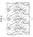
- a plurality of intake valves 3 and a plurality of exhaust valves 4 are positioned within a plurality of cylinders 2 of a cylinder block 10 (see Fig. 1), and intake ports 5 and exhaust ports 6 are formed from those valves 3 and 4 as the respective intake and exhaust ports.
- a plurality of boss portions 8 each having a head bolt hole 7 are disposed on the cylinder head 1 side between the respective cylinders 2 of the cylinder block 10.
- Fig. 2 schematically shows the positional relationship of the intake ports 5, the exhaust ports 6 and the boss portions 8, but an upper-surface deck 17 and a lower-surface deck 15 which will be described later are omitted from Fig. 2.
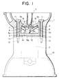
- Fig. 1 shows a cross-sectional view of the main portion of the cylinder head 1 taken along a line X-X in Fig.2.
- the cylinder head 1 is fixed to the cylinder block 10 by fastening the head bolts 11 in a state where the gasket 9 for holding air tight is interposed between the cylinder head 1 and the cylinder block 10.
- the cylinder block 10 has the cylinders 2 and screw holes 12 for fastening the head bolts 11, and the gasket 9 has through-holes 13 for the head bolts 11 and through-holes 14 for the cylinders 2. Then, each of the head bolt holes 7 of the cylinder head 1, each of through-holes 13 for the head bolts 11 of the gasket 9 and each of screw holes 12 of the cylinder block 10 are allowed to coincide with each other so as to form a communicating hole. Each of the head bolts 11 is inserted and fastened into the respective communicating holes, to thereby fix the cylinder head 1 to the cylinder block 10 by fastening in a state where the gasket 9 is interposed between the cylinder head 1 and the cylinder block 10.
- a plurality of boss portions 8 having head bolt holes 7 are formed on the inner portions of both sides of the cylinder head 1.
- an upper-surface deck 17 is formed on an upper portion interposed between the boss portions 8 in the form of a plane whereas a lower-surface deck 15 is formed on a lower portion interposed between the boss portions 8 in the form of a plane, and a substantially-pipe-shaped intake port 5 is disposed so as to extend upward from an intermediate portion 15a of the lower-surface deck 15.
- Intake air flows from the intake ports 5 toward the intake valves 3 (see Fig. 2) disposed within the opening portions 15b of the lower-surface deck 15 so that the intake air is supplied to the interior of the cylinders 2.
- cooling water is circulatively supplied to a space defined between the upper-surface deck 17 and the lower-surface deck 15.
- ribs 16 are disposed in the form of V from an upper portion 8a of the boss portions 8 toward a lower portion 5a of the intake ports 5, and the boss portions 8 and the intake ports 5 are connected and supported by the ribs 16 straightly at the shortest distance.
- the boss portions 8 are supported in a state where the ribs 16 interpose the intake port 5 therebetween.
- a strut 5b is formed on the lower portion 5a of each of the intake ports 5 and pushes a portion of the lower-surface deck 15 corresponding to the vicinity of the outer periphery of the cylinder 2.
- the present invention is not limited to the above embodiment but may be implemented as follows:
- the ribs 16 are connected and supported from the upper portion 8a of the boss portions 8 for the head bolts 11 toward the lower portion 5a of the intake ports 5.
- the intake ports 5 may be replaced by whatever extends upward from the intermediate portion 15a of the lower-surface deck 15 and can support the boss portions 8.
- the exhaust ports 6 or the like may be replaceably disposed at the position of the intake ports 5 in the above embodiment.
- the ribs 16 are connected and supported from the upper portion 8a of the boss portions 8 for the head bolts 11 toward the lower portion 5a of the intake ports 5.
- the ribs may be connected and supported toward the lowermost of the intake ports 5, that is, toward the intermediate portion 15a of the lower-surface deck 15 in the vicinity of a root of the intake ports 5.
- a cylinder head 1 has boss portions 8 for head bolts 11 which are formed inside of both sides of the cylinder head 1, and a discharge/intake port 5 which extends from an intermediate portion 15a of a lower-surface deck 15 that is in contact with a gasket 9.
- ribs 16 are connected and supported from an upper portion 8a of the boss portions 8 toward a lower portion 5a of the intake port 5.
Landscapes
- Engineering & Computer Science (AREA)
- Chemical & Material Sciences (AREA)
- Combustion & Propulsion (AREA)
- Mechanical Engineering (AREA)
- General Engineering & Computer Science (AREA)
- Cylinder Crankcases Of Internal Combustion Engines (AREA)
Abstract
Description
Claims (3)
- A cylinder head (1) for use in an internal combustion engine comprising: boss portions (8) for head bolts; a lower-surface deck (15) which is in contact with a gasket (9); and an intake or an exhaust port (4, 5) formed to extend upward from an intermediate portion (15a) of said lower-surface deck (15) which is disposed between the boss portions (8);
characterized in that
the cylinder head (1) comprises ribs (16) that connect an upper portion (8a) of the boss portion (8) and a lower portion (5a) of at least one port (4, 5) or said intermediate portion (15a) of said lower-surface deck (15) in the vicinity of a root of said port (4, 5). - The cylinder head for use in an internal combustion engine as claimed in claim 1, characterized in that said ribs (16) connect said boss portions (8) and the lower portion (5a) of said port (4, 5) straightly at the shortest distance.
- The cylinder head for use in an internal combustion engine as claimed in claim 2, characterized in that said ribs (16) are formed in the form of beams.
Applications Claiming Priority (2)
| Application Number | Priority Date | Filing Date | Title |
|---|---|---|---|
| JP33114099 | 1999-11-22 | ||
| JP33114099 | 1999-11-22 |
Publications (2)
| Publication Number | Publication Date |
|---|---|
| EP1101922A2 true EP1101922A2 (en) | 2001-05-23 |
| EP1101922A3 EP1101922A3 (en) | 2002-05-02 |
Family
ID=18240328
Family Applications (1)
| Application Number | Title | Priority Date | Filing Date |
|---|---|---|---|
| EP00123126A Withdrawn EP1101922A3 (en) | 1999-11-22 | 2000-10-25 | Cylinder head for use in an internal combustion engine |
Country Status (1)
| Country | Link |
|---|---|
| EP (1) | EP1101922A3 (en) |
Cited By (1)
| Publication number | Priority date | Publication date | Assignee | Title |
|---|---|---|---|---|
| CN108138688A (en) * | 2015-08-26 | 2018-06-08 | 福特汽车萨纳伊股份有限公司 | Cylinder head |
Family Cites Families (5)
| Publication number | Priority date | Publication date | Assignee | Title |
|---|---|---|---|---|
| JPS57163141A (en) * | 1981-03-31 | 1982-10-07 | Yamaha Motor Co Ltd | Cylinder head clamping structure in internal- combustion engine |
| FR2528511A1 (en) * | 1982-06-14 | 1983-12-16 | Peugeot | BEARING CAP FOR CAMSHAFT AT HEAD OF INTERNAL COMBUSTION ENGINE, AND CORRESPONDING ENGINE |
| DE3603582C1 (en) * | 1986-02-06 | 1987-03-05 | Bayerische Motoren Werke Ag | Method for machining a channel arranged in a casting |
| KR100233933B1 (en) * | 1995-05-15 | 1999-12-15 | 나까무라히로까즈 | Manufacturing method for intake structure and intake channel of internal engine |
| JPH10331709A (en) * | 1997-05-29 | 1998-12-15 | Suzuki Motor Corp | Cylinder head structure of internal combustion engine |
-
2000
- 2000-10-25 EP EP00123126A patent/EP1101922A3/en not_active Withdrawn
Cited By (1)
| Publication number | Priority date | Publication date | Assignee | Title |
|---|---|---|---|---|
| CN108138688A (en) * | 2015-08-26 | 2018-06-08 | 福特汽车萨纳伊股份有限公司 | Cylinder head |
Also Published As
| Publication number | Publication date |
|---|---|
| EP1101922A3 (en) | 2002-05-02 |
Similar Documents
| Publication | Publication Date | Title |
|---|---|---|
| EP0628716B1 (en) | Cylinder block for an internal combustion engine | |
| US20040123591A1 (en) | 4-Cycle engine for motorcycle | |
| US4520771A (en) | Internal combustion engine | |
| US6659058B2 (en) | Intake system of a V-type engine | |
| JPH10331709A (en) | Cylinder head structure of internal combustion engine | |
| JP3323434B2 (en) | Engine with breather device | |
| JPH01163410A (en) | Valve system of engine | |
| JPH0210275Y2 (en) | ||
| CN1070264C (en) | Cylinder head for a direct-injection internal-combustion engine | |
| JPH11182368A (en) | Engine head structure | |
| JPH06213064A (en) | Structure of cylinder block in internal combustion engine | |
| JP3849662B2 (en) | Cylinder head structure of direct injection diesel engine | |
| JPH11200941A (en) | Engine structure | |
| JPH08303295A (en) | Engine cylinder block | |
| JPH0299724A (en) | Mounting structure of knock sensor for v-type engine | |
| JPH0115877Y2 (en) | ||
| JP2001214802A (en) | Cylinder head for internal combustion engine | |
| JPH0224932Y2 (en) | ||
| JPH10213051A (en) | Clamp structure of fuel injection nozzle | |
| JP3494335B2 (en) | Internal combustion engine | |
| JP2005214156A (en) | Structure for intake system and exhaust system of engine | |
| JPS6347634Y2 (en) | ||
| JP2007177690A (en) | Exhaust manifold | |
| JPH102250A (en) | Mounting structure of the intake manifold | |
| JPH11350969A (en) | Installation device of throttle body in slanted internal combustion engine |
Legal Events
| Date | Code | Title | Description |
|---|---|---|---|
| PUAI | Public reference made under article 153(3) epc to a published international application that has entered the european phase |
Free format text: ORIGINAL CODE: 0009012 |
|
| 17P | Request for examination filed |
Effective date: 20001025 |
|
| AK | Designated contracting states |
Kind code of ref document: A2 Designated state(s): AT BE CH CY DE DK ES FI FR GB GR IE IT LI LU MC NL PT SE Kind code of ref document: A2 Designated state(s): DE FR IT |
|
| AX | Request for extension of the european patent |
Free format text: AL;LT;LV;MK;RO;SI |
|
| RAP1 | Party data changed (applicant data changed or rights of an application transferred) |
Owner name: KABUSHIKI KAISHA TOYOTA JIDOSHOKKI |
|
| PUAL | Search report despatched |
Free format text: ORIGINAL CODE: 0009013 |
|
| AK | Designated contracting states |
Kind code of ref document: A3 Designated state(s): AT BE CH CY DE DK ES FI FR GB GR IE IT LI LU MC NL PT SE |
|
| AX | Request for extension of the european patent |
Free format text: AL;LT;LV;MK;RO;SI |
|
| AKX | Designation fees paid |
Free format text: DE FR IT |
|
| STAA | Information on the status of an ep patent application or granted ep patent |
Free format text: STATUS: THE APPLICATION IS DEEMED TO BE WITHDRAWN |
|
| 18D | Application deemed to be withdrawn |
Effective date: 20021031 |