EP1101888B1 - Universelle Sicherungsvorrichtung für Umreifung - Google Patents
Universelle Sicherungsvorrichtung für Umreifung Download PDFInfo
- Publication number
- EP1101888B1 EP1101888B1 EP00123941A EP00123941A EP1101888B1 EP 1101888 B1 EP1101888 B1 EP 1101888B1 EP 00123941 A EP00123941 A EP 00123941A EP 00123941 A EP00123941 A EP 00123941A EP 1101888 B1 EP1101888 B1 EP 1101888B1
- Authority
- EP
- European Patent Office
- Prior art keywords
- locking
- fastener
- security device
- ratchet
- base
- Prior art date
- Legal status (The legal status is an assumption and is not a legal conclusion. Google has not performed a legal analysis and makes no representation as to the accuracy of the status listed.)
- Expired - Lifetime
Links
Images


Classifications
-
- A—HUMAN NECESSITIES
- A45—HAND OR TRAVELLING ARTICLES
- A45C—PURSES; LUGGAGE; HAND CARRIED BAGS
- A45C13/00—Details; Accessories
- A45C13/18—Devices to prevent theft or loss of purses, luggage or hand carried bags
- A45C13/20—Chains or bands
-
- A—HUMAN NECESSITIES
- A47—FURNITURE; DOMESTIC ARTICLES OR APPLIANCES; COFFEE MILLS; SPICE MILLS; SUCTION CLEANERS IN GENERAL
- A47F—SPECIAL FURNITURE, FITTINGS, OR ACCESSORIES FOR SHOPS, STOREHOUSES, BARS, RESTAURANTS OR THE LIKE; PAYING COUNTERS
- A47F3/00—Show cases or show cabinets
- A47F3/002—Devices for protection against sunlight or theft
-
- E—FIXED CONSTRUCTIONS
- E05—LOCKS; KEYS; WINDOW OR DOOR FITTINGS; SAFES
- E05B—LOCKS; ACCESSORIES THEREFOR; HANDCUFFS
- E05B35/00—Locks for use with special keys or a plurality of keys ; keys therefor
- E05B35/008—Locks for use with special keys or a plurality of keys ; keys therefor for simple tool-like keys
-
- E—FIXED CONSTRUCTIONS
- E05—LOCKS; KEYS; WINDOW OR DOOR FITTINGS; SAFES
- E05B—LOCKS; ACCESSORIES THEREFOR; HANDCUFFS
- E05B73/00—Devices for locking portable objects against unauthorised removal; Miscellaneous locking devices
- E05B73/0017—Anti-theft devices, e.g. tags or monitors, fixed to articles, e.g. clothes, and to be removed at the check-out of shops
- E05B73/0029—Tags wrapped around the protected product using cables, wires or the like, e.g. with cable retraction for tensioning
-
- Y—GENERAL TAGGING OF NEW TECHNOLOGICAL DEVELOPMENTS; GENERAL TAGGING OF CROSS-SECTIONAL TECHNOLOGIES SPANNING OVER SEVERAL SECTIONS OF THE IPC; TECHNICAL SUBJECTS COVERED BY FORMER USPC CROSS-REFERENCE ART COLLECTIONS [XRACs] AND DIGESTS
- Y10—TECHNICAL SUBJECTS COVERED BY FORMER USPC
- Y10T—TECHNICAL SUBJECTS COVERED BY FORMER US CLASSIFICATION
- Y10T24/00—Buckles, buttons, clasps, etc.
- Y10T24/14—Bale and package ties, hose clamps
- Y10T24/1402—Packet holders
- Y10T24/1404—Cord
-
- Y—GENERAL TAGGING OF NEW TECHNOLOGICAL DEVELOPMENTS; GENERAL TAGGING OF CROSS-SECTIONAL TECHNOLOGIES SPANNING OVER SEVERAL SECTIONS OF THE IPC; TECHNICAL SUBJECTS COVERED BY FORMER USPC CROSS-REFERENCE ART COLLECTIONS [XRACs] AND DIGESTS
- Y10—TECHNICAL SUBJECTS COVERED BY FORMER USPC
- Y10T—TECHNICAL SUBJECTS COVERED BY FORMER US CLASSIFICATION
- Y10T70/00—Locks
- Y10T70/40—Portable
- Y10T70/413—Padlocks
- Y10T70/437—Key-controlled
- Y10T70/483—Flexible shackle
-
- Y—GENERAL TAGGING OF NEW TECHNOLOGICAL DEVELOPMENTS; GENERAL TAGGING OF CROSS-SECTIONAL TECHNOLOGIES SPANNING OVER SEVERAL SECTIONS OF THE IPC; TECHNICAL SUBJECTS COVERED BY FORMER USPC CROSS-REFERENCE ART COLLECTIONS [XRACs] AND DIGESTS
- Y10—TECHNICAL SUBJECTS COVERED BY FORMER USPC
- Y10T—TECHNICAL SUBJECTS COVERED BY FORMER US CLASSIFICATION
- Y10T70/00—Locks
- Y10T70/50—Special application
Definitions
- This invention relates to a security device. More particularly the invention relates to an adjustable security device which wraps around and secures a box, book, or other similarly structured article of indefinite size in a closed position. Even more particularly the invention relates to a universal wrap security device which includes cable means that wrap around the article and extend between ratchet means and locking means.
- Retail stores have a difficult time protecting boxes containing various expensive merchandise, books and other similarly structured packages or objects from being opened and the contents thereof being removed without authorization from store personnel or damaged while on display. Consumers often want to visually inspect the packaged expensive articles before deciding to purchase them. The store is faced with the problem of how to protect these expensive articles from theft while displaying them for sale.
- One method used to protect these packages and the articles contained therein is to enclose the article within a transparent glass display case which can only be accessed from behind a counter of the retail store. The consumer can view the article through the glass but is not able to handle the article or read any of the information about the article that may be printed on the box unless a store clerk removes the article from the case.
- a store clerk removes the article from the case.
- the problem then arises of getting the selected merchandise to the customer after the customer wishes to purchase the same without subjecting the merchandise to theft.
- One manner is to maintain a supply of the boxes containing the expensive articles or merchandise close at hand for delivery to or pick-up by the customer for subsequent taking to a check-out clerk. However this makes the boxes susceptible to theft.
- Another method used by retail stores is to list the article in a catalog and require consumers to place an order from the catalog.
- the article is delivered from a back storage area and the consumer must simultaneously pick up and pay for the merchandise at the same location to prevent unauthorized removal from the store.
- the consumer does not get to inspect the article before purchasing and if they are not satisfied they must undergo the hassle of returning the article for a refund.
- Boxes and box-like structures are also subjected to unauthorized openings while being shipped via a courier. These articles can be easily opened and resealed when packaged and taped-shut in the conventional manner without the recipient or the sender knowing of such actions. Shipped packages can be secured within a security container with a locking mechanism but these containers are expensive to purchase and add size and weight to the package making it more expensive to ship. Also, would-be thieves can gain unauthorized access to the contents of these containers by "picking" the locking mechanisms or possibly guessing the combination to a combination lock.
- US-A-3/611,760 discloses a locking device which utilizes a retractable cable mounted in a housing, wherein the cable loops around an object to be secured, and is then locked in the housing by a combination lock.
- US-A-4,756,171 discloses a locking device having a cable which extends about the object to be secured, together with a take-up reel mounted in the lock member for tightening the cable by a crank handle in the lock member.
- US-A-4,896,517 discloses a locking device which has a cable with a locking head wound about a reel having a ratchet and pawl locking mechanism. The locking head engages the locking mechanism to secure the cable in a locked position.
- US-A-5,156,028 discloses a portable locking device according to the preamble of appended claim 1, using a ratchet-like retrieving reel, to which is connected a locking cable.
- US-A-3,831,407 discloses a locking device consisting of a plurality of flexible wire-like members which extend about an object to be secured, with open ends of the chains being secured by a lock.
- US-A-4,418,551 discloses a security device which is mounted about a rectangular object, such as a vending machine.
- the device includes a strap structure extending around portions of the rectangular object, a door moveable between open and closed positions, and a locking mechanism to lock the door in the closed position.
- US-A-4,930,324 discloses a lockable buckle which has a rotatably mounted tumbler in a lock housing which locks a clasp member to the housing.
- none of these prior art devices include a portable lightweight device which has ratchet means which is operable to tighten cables or cable sections around box-like structures of various sizes, and which has a two-piece locking means the pieces of which snap-fit together and which can be released, e.g. by using an unlocking tool or key with magnetic arms to dismantle the two-piece locking means,- before the article contained within the box can be removed therefrom.
- the security device is used to secure a right parallelepipedic package with the cable means enclosing the package on all six sides.
- the ratchet means is suitably a one-way ratchet which can be released only after the device has been removed from the package.
- the security device is intended to be reusable indefinitely, is not intended to add significant size or weight to the package, and which is readily adjustable for a variety of sized boxes or packages.
- the locking means conveniently requires the use of an unlocking tool to release the base and fastener from their snap-fit engagement.
- the ratchet means conveniently also requires a tool to tighten the cable means around the package being protected,
- the ratchet means includes a gear with a plurality of teeth and a one-way pawl which engages the teeth.
- the pawl can only be disengaged from the ratchet teeth only from a rear side of the ratchet means after the device has been removed from the package.
- the security device is made of high-strength plastics material which is not readily affected by chemicals and moisture.
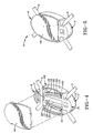
- a universal wrap security device of the present invention is indicated generally at 1 and is shown locked to a package 2 in FIG. 1.
- the security device 1 includes a locking member 3, a ratchet member 4 and a plurality of connecting cables 5.
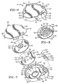
- the locking member 3 includes two main components, namely an oval-shaped base 8 and a fastener 7 (FIGS. 2-5) which is inserted and locks into the oval-shaped base 8.
- the fastener 7 has a leg 10 (FIGS. 2 and 3) integrally formed with and extending from an ear shaped lug 11.
- the leg 10 includes a rectangular-shaped centre post 13 intermediate two spaced, generally parallel, tangs 15 and 16.
- a U-shaped groove 14 is formed in a back side of the post 13.
- each tang 15 and 16 is angled inwardly toward post 13, and the post 13 and tangs 15 and 16 are connected integrally at a free end 17 of the leg 10.
- the end 17 has rounded edges 18 which extend beyond the inwardly angled portions of the tangs 15 and 16 and form flat locking tabs 19.
- a circular opening 22 is formed in the lug 11 and allows cable 5 to extend therethrough.
- a pair of notches 23 is formed in each side of lug the 11 on a flat side thereof. These notches assist in guiding the fastener 7 into the base 8 and centrally stabilize the fastener 7 therein, as described below in further detail.
- the base 8 includes an oval-shaped bottom member 26 which has an upstanding curved side wall 27 extending partially around the perimeter of the bottom member 26, and a pair of end walls 28 extending inwardly from opposite ends of the wall 27.
- a pair of tapered prongs 29 extends inwardly perpendicularly from an end of each end wall 28.
- a pair of tabs 30 extends inwardly parallel to a tapered edge of the prongs 29 and further extends from the end walls 28 between the outer wall 27 and the prongs 29.
- a pair of substantially L-shaped metal tines 35 is inserted and secured between the prongs 29 and tabs 30. These tines extend angularly inwardly and terminate adjacent a second end wall 39 (FIGS. 3 and 4).
- the wall 39 is spaced from and is parallel to the end walls 28 and a third end wall 40 is spaced outwardly from and parallel to the second end wall 39 forming a channel 42 therebetween through which another portion of cable 5 extends.
- An elongated rib 34 is perpendicular to the wall 39 and extends inwardly partially across the longitudinal length of the bottom member 26 of base 8 and is received in the groove 14 of fastener 7 when the locking member 3 is in a locked position as shown in FIGS. 4 and 5.
- An oval shaped cover 44 (FIGS. 2-5) generally similar in size to the bottom member 26 encloses the base 8 and is seated upon a generally oval-shaped shoulder 45 formed inside of and extending along the side wall 26.
- the leg 10 of the fastener 7 slides between the prongs 29 when pressure is applied to the fastener 7 in the direction of arrow A (FIG. 4), and the groove 14 of the leg 10 receives and is guided by the rib 34.
- the rounded edges 18 of the end 17 deflect the tines 35 outwardly as the fastener 7 is inserted into the base 8.
- the lug 11 fills an open area 36 (FIGS. 2 and 3) of the bottom member 26 and abuts the end walls 28.
- Notches 23 receive a pair of shoulders 37 which are formed on each end of the wall 27, and the resiliency of the metal tines 35 causes them to snap into a locked position adjacent to the angular outer portions of the tangs 15 and 16.
- the tines 35 cooperate with the tabs 19 of the leg 10 and prevent the fastener 7 from being removed from the base 8.
- the locking member 3, except for the metal tines 35, is preferably formed of a lightweight, high-strength plastics material which is relatively rust free and unaffected by chemicals and harsh environments to which it may be exposed, with the base 8 and cover plate 44 being moulded as one-piece members and subsequently secured together by an adhesive, ultrasonic welding, or other type of securement means.
- the ratchet member 4 is shown assembled in FIG. 6 and unassembled in FIG. 7.
- the ratchet member 4 includes a housing 50 which is separated into a generally circular compartment 51 and a smaller adjacent compartment 53 by a partition wall 55.
- a circular-shaped bearing member 54 and a circular-shaped gear 56 are housed within the compartment 51 and a pawl 52 is housed within the compartment 53. Both compartments 51 and 53 and the contents therein are enclosed by a bottom plate 58.
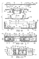
- a circular opening 60 is formed in a front wall 62 of the housing 50 and an annular groove or bearing surface 64 is formed around the circular opening 60.
- the side wall 65 of the housing 50 extends vertically upwardly from the front wall 62 and includes an outwardly extending lip or shoulder 66 upon which the bottom plate 58 sits when secured to the housing 50.
- U-shaped openings 68 are formed in the side wall 65 in a square-shaped configuration and allow four cable sections to pass therethrough, with each cable section being generally perpendicular to the adjacent two cable sections.
- the bottom plate 58 includes four flanges 69 with an arcuate shaped bottom, which align and cooperate with U-shaped openings 68 to form circular shaped openings 70 therebetween (FIG. 6).
- FIG. 7 Another circular opening 73 is formed in the centre of bearing member 54 (FIG. 7) and an annular nub 75 (FIG. 9), which corresponds to and is received by bearing surface 64, is formed on a bottom surface of the bearing member 54.
- Four flexible projections 76 (FIGS. 7 and 9), which include outward extending latching tabs 77, extend orthogonally from the bearing member 54 and are arranged in a square-shaped configuration.
- the gear 56 is shown particularly in FIGS. 7 and 8 and releasably latches to bearing member 54 when the ratchet member 4 is assembled as shown in FIGS. 10 and 11.
- a plurality of teeth 80 extend around an outside edge of the gear 56.
- the gear 56 further includes a disc-shaped plate 82 and a centre hub 84 which extends vertically from the plate 82.
- Four openings 85 are formed in the hub 84 for receiving and retaining an enlarged end 88 of each section of cable 5 as shown in FIG. 12.
- Four irregular-shaped holes 90 are formed in the hub 84 partially therethrough and four rectangular-shaped holes 91 which communicate with holes 90 are formed completely through the gear 56 (FIG. 12).
- the holes 91 receive projections 76 of the bearing member 54 and allow latching tabs 77 to secure the bearing member 54 to the gear 56 to form a cable-receiving reel 100.
- a bore 94 is formed through the centre of gear 56 and includes a seven sided surface 95 formed in the hub 84, a smaller circular opening 96 formed in an annular plate 99 concentrically with and adjacent to the seven sided surface 95 (FIGS. 7, 8, 9 and 12) and a larger circular section 97 formed in the plate 82 concentrically with and adjacent to the circular opening 96 and annular plate 99.
- An annular nub 101 is formed on a top surface of the plate 82 of the gear 56 concentrically with the bore 94 and is received by a bearing surface 71 formed in the bottom plate 58 when the ratchet member 4 is assembled as shown in FIGS. 9 and 10.
- the pawl 52 has a cylindrical base 105 (FIG. 7), a smaller cylindrical section 106 which has a five-sided central opening 107 formed therein, a resilient spring 108 and a pawl catch 110, both of which extend from a side wall of the cylindrical section 105.
- the pawl 52 is mounted in the compartment 53 and is seated upon a circular boss 103 formed on the wall 62 (FIG. 11).
- the cylindrical section 106 extends through a complementary-shaped hole 59 formed in the bottom plate 58 (FIGS. 6 and 7) which clamps the pawl 52 within the housing 50.
- a resilient spring 108 applies pressure on the inside of the side wall 65 forcing catch 110 to extend through a rectangular-shaped opening 57 formed in the partition wall 55 and to selectively contact the teeth 80 of the gear 56 (FIG. 13).
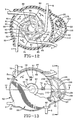
- the gear 56, bearing member 54 and hub 84 form a reel 100 when snap-fitted together (FIG. 10) on which cables 5 are wound and unwound when ratchet member 4 is operated as described below.
- the bearing member 54 lies in the circular compartment 51 on the front wall 62 with the annular nub 75 sitting in the bearing surface 64.
- Two cables 5 are inserted into the hub 84 of the gear 56 with each enlarged end 88 of the cables secured in opposite openings 85 and with each end of the cables extending through opposite openings 70 oriented 90° with respect to the adjacent openings.
- the gear 56 is latched to the bearing member 54 as described above enclosing an open end of the hub 84 and locking the cables therein.
- the pawl 52 is placed in the compartment 53 and the bottom plate 58 sits on the lip 66 and is secured to the housing 50 enclosing the compartments 51 and 53.
- the annular nub 101 of the gear 56 sits in the bearing surface 71 of the bottom plate 58 and along with the annular nub 75 and bearing surface 64 allow the gear 56 and bearing member 54 to rotate when cable 5 is dispensed from or collected on the reel 100.
- the ratchet member 4 is placed against a side of the package 2 (FIG. 1) so that the bore 94 is exposed for receiving a seven-sided section 117 of a ratchet tool 115 (FIGS. 1 and 13).
- the fastener 7 and base 8 are snap-fitted together (arrow A, FIG. 4) securing the locking member 3 in a locked position and locking the universal wrap 1 around the package 2.
- the surface 117 of the tool 115 is inserted into the multi-sided surface 95 and the tool 115 is rotated to turn the gear 56 and bearing member 54 in the direction of arrows B (FIG. 13).
- the catch 110 of the pawl 52 catches in the teeth 80 of the gear 56 as the gear is rotated, preventing reel 100 from rotating in a direction opposite to that of arrow B.
- the cables 5 are tightened around the package 2 and are collected on the reel 100 as the tool 115 is turned in the direction of arrows B.
- the tool 115 is turned until the cables 5, locking member 3 and ratchet member 4 are firmly secured around and against the package 2, thus preventing the removal of the security device 1 from the package and preventing any unauthorized opening thereof.
- the universal wrap 1 is removed by placing a key or unlocking tool 120 adjacent the locking member 3 as shown by dot-dash lines in FIG. 15.
- the tool 120 includes a base 122 with a pair of angled magnet support arms 121 on which are mounted permanent magnets 123.
- a support rib 124 is formed on the base 122 and extends upwardly therefrom and extends between arms 121 for properly positioning and guiding the locking member 3 into position between the magnets 123.
- the magnetic field of the magnets 123 causes the metal tines 35 to move outwardly a sufficient distance to allow the end 17, and particularly the locking tabs 19 of the fastener 7, to pass therethrough, thus allowing the fastener 7 to be manually removed from its latched condition with the base 8.
- the cable 5 is loose enough to allow the device 1 to be removed from the package 2.
- the five-sided section 118 of the ratchet tool 115 (FIG. 14) can then be inserted into the five-sided opening 107 of the pawl 52 after it has been removed from the package, and turned in the direction of arrow C (FIG. 12), releasing the catch 110 from the teeth 80 by compressing the spring 108 against the side wall 65, making the reel 100 freewheeling, as shown by arrows D.
- a lockout tab 61 which can be formed as a separate member or as a part of bottom plate 58, is pressed outwardly by a ramped end 109 of spring the 108. As shown in FIGS.
- the tab 61 will have a multi-ramped bottom section which when engaged by the ramped end 109 of the spring 108 will engage the outer edge 109a of the spring 108, moving the tab 61 into an extended position above the peripheral edge 67 of the side wall 65, as shown by dot-dash lines in FIG. 10. This then enables the cables 5 to be freely unwound for placement about another package, after which the multi-sided section 117 of the tool 115 is used to rotate the reel 100 and tighten the cables 5 about a different package.
- the lockout tab 61 is automatically released from the ramped end 109 of the spring 108 by placing the member 3 against a package which pushes tab 61 inwardly disengaging the spring 108 therefrom enabling the spring 108 to return to its operative position, as shown in solid lines in FIGS. 10, 11 and 13, and move the catch 110 into engagement with the teeth 80.
- the universal wrap is then ready to be secured around the package as described above.
- the security device 1 is wrapped and secured around the package 2, preventing the package from being opened.
- Cables 5 extend through the fastener 7 and the base 8 of the locking member 3 and the fastener and base are snap-fitted together.
- the metal tines 35 lock under the locking tabs 19 securing the fastener 7 to the base 8.
- the annular nubs 75 and 101 sit in the bearing surfaces 64 and 71, respectively, allowing the bearing reel 100 to rotate freely within the housing 50.
- the catch 110 of the pawl 52 catches in the teeth 80 of the gear 56 allowing the reel to rotate in only one direction.
- the seven-sided key 117 of the tool 115 rotates the reel tightening and securing the cables 5 and thus the universal wrap 1 around the package 2.
- the magnets 123 of the unlocking tool 120 cause the metal tines 35 to deflect outwardly allowing the fastener 7 to be dismantled from the base 8 and further allowing the security device 1 to be removed from the package 2.
- the tool 115 is used to disengage the pawl 52 from the teeth 80, as well as to tighten cables 5 about an object.
- the lockout device 61 also allows the cables 5 to be wound and stored on the reel for future use of the security device.
- the cables 5 could be replaced with other flexible members made of plastics, chains, fibres, and similar materials, and will be covered by the term “cables” as used in the above description.
- the locking member 3 will be formed of a high-strength plastics material, with the exception of the metal tines 35, thereby rendering it unaffected by moisture, chemicals and other harsh environments in which it may be used, and will prevent it from marring the objects on which it is mounted.
- the ratchet member 4 is constructed of a similar high-strength plastics material, providing similar advantages as those discussed above with respect to the locking member 3.
- an electronic article surveillance tag (EAS) 112 can be mounted on the rear surface of the locking member 3, as shown in FIG. 1, or on the rear surface of the ratchet member 4, when used in a retail store having an EAS security system at the exit, to prevent unauthorized removal of the package.
- the security device 1 can be used to securely retain a package or object in a closed position, as well as preventing its removal from a retail store having such EAS security systems.
- the improved security device is simplified, provides an effective, safe, inexpensive, and efficient device which achieves all the enumerated objectives, provides for eliminating difficulties encountered with prior devices, and solves problems and obtains new results in the art.
Claims (5)
- Sicherungsvorrichtung (1), die um einen Gegenstand (2) gelegt werden kann, um zu verhindern, dass der Gegenstand geöffnet wird, wobei die Vorrichtung Folgendes umfasst: ein Kabelmittel (5), das um einen zu sichernden Gegenstand (2) herum zu legen ist, ein mit dem Kabelmittel (5) verbundenes Ratschenmittel (4) zum Spannen des Kabelmittels um den Gegenstand und ein Verriegelungsmittel (3) mit einer Basis (8) und einer Halterung (7), die jeweils mit dem Kabelmittel verbunden sind und freigebbar miteinander in einer Schnappverbindung in Eingriff gebracht werden können, um das Kabelmittel (5) freigebbar um den Gegenstand zu verriegeln, dadurch gekennzeichnet, dass die Basis (8) und die Halterung (7) des Verriegelungsmittels ein Verriegelungsglied (3) bilden, das von dem Ratschenmittel (4) beabstandet und getrennt ist.
- Sicherungsvorrichtung nach Anspruch 1, dadurch gekennzeichnet, dass die Halterung (7) Laschen (15, 16) und die Basis (8) Metallzinken (35) umfasst, die mit den Verriegelungslaschen (15, 16) der Halterung zusammenwirken, um die Halterung (7) freigebbar an der Basis (8) zu befestigen.
- Sicherungsvorrichtung nach Anspruch 1 oder 2, dadurch gekennzeichnet, dass sie weiterhin ein Entriegelungswerkzeug (120) mit Magneten (123) umfasst, die die Metallzinken (35) aus den Verriegelungslaschen (15, 16) der Halterung (7) ausrücken.
- Sicherungsvorrichtung nach einem der vorhergehenden Ansprüche, dadurch gekennzeichnet, dass das Ratschenmittel (4) ein Gehäuse (50), eine drehbar in dem Gehäuse (50) zum Stützen des Kabelmittels (5) angeordnete Spule (100) und eine Klinke (52) umfasst, die die Spule (100) betriebsmäßig in Eingriff nimmt, um die Spule (100) ratschenmäßig in eine feste Position zu bringen, um das Kabelmittel (5) um den Gegenstand herum gespannt zu halten.
- Sicherungsvorrichtung nach Anspruch 4, dadurch gekennzeichnet, dass die Spule (100) eine Nabe (84) und einen ersten und einen zweiten Endflansch (56, 54), die voneinander beabstandet sind, umfasst, wobei um einen Außenrand des ersten Flansches (56) herum mehrere Zähne (80) und in der Nabe (84) zur Aufnahme vergrößerter Enden (88) des Kabelmittels (5) mehrere Öffnungen (85) ausgebildet sind, um das Kabelmittel an der Nabe zu befestigen.
Applications Claiming Priority (3)
| Application Number | Priority Date | Filing Date | Title |
|---|---|---|---|
| US08/561,370 US5722266A (en) | 1995-11-21 | 1995-11-21 | Universal wrap security device |
| US561370 | 1995-11-21 | ||
| EP96913302A EP0862677B1 (de) | 1995-11-21 | 1996-05-06 | Universelle sicherungsvorrichtung für umreifung |
Related Parent Applications (1)
| Application Number | Title | Priority Date | Filing Date |
|---|---|---|---|
| EP96913302A Division EP0862677B1 (de) | 1995-11-21 | 1996-05-06 | Universelle sicherungsvorrichtung für umreifung |
Publications (2)
| Publication Number | Publication Date |
|---|---|
| EP1101888A1 EP1101888A1 (de) | 2001-05-23 |
| EP1101888B1 true EP1101888B1 (de) | 2003-03-19 |
Family
ID=24241663
Family Applications (2)
| Application Number | Title | Priority Date | Filing Date |
|---|---|---|---|
| EP96913302A Expired - Lifetime EP0862677B1 (de) | 1995-11-21 | 1996-05-06 | Universelle sicherungsvorrichtung für umreifung |
| EP00123941A Expired - Lifetime EP1101888B1 (de) | 1995-11-21 | 1996-05-06 | Universelle Sicherungsvorrichtung für Umreifung |
Family Applications Before (1)
| Application Number | Title | Priority Date | Filing Date |
|---|---|---|---|
| EP96913302A Expired - Lifetime EP0862677B1 (de) | 1995-11-21 | 1996-05-06 | Universelle sicherungsvorrichtung für umreifung |
Country Status (10)
| Country | Link |
|---|---|
| US (2) | US5722266A (de) |
| EP (2) | EP0862677B1 (de) |
| JP (1) | JP3953516B2 (de) |
| AU (2) | AU708423B2 (de) |
| BR (1) | BR9611740A (de) |
| CA (1) | CA2238042C (de) |
| DE (2) | DE69626874T2 (de) |
| HU (1) | HUP9901468A3 (de) |
| MX (1) | MX9803710A (de) |
| WO (1) | WO1997019241A1 (de) |
Families Citing this family (78)
| Publication number | Priority date | Publication date | Assignee | Title |
|---|---|---|---|---|
| US6092401A (en) * | 1999-02-18 | 2000-07-25 | Alpha Enterprises, Inc. | Electronic article surveillance security device |
| US6125669A (en) * | 1999-08-25 | 2000-10-03 | Kryptonite Corporation | Portable security frame for portable articles |
| US6298695B1 (en) * | 1999-12-06 | 2001-10-09 | Donald Vezina | Equipment security apparatus |
| US6167734B1 (en) * | 2000-01-10 | 2001-01-02 | Jay S Derman | Security cable coupling device |
| US6233985B1 (en) * | 2000-01-14 | 2001-05-22 | Fu-Chuan Huang | Coupling lock |
| US6164291A (en) * | 2000-03-02 | 2000-12-26 | Filippone; Thomas C. | Retracting hairholder device |
| US6427499B1 (en) * | 2000-10-05 | 2002-08-06 | Jay S Derman | Portable equipment security device |
| US6755055B2 (en) | 2002-02-26 | 2004-06-29 | Alpha Security Products, Inc. | Theft deterrent device |
| US20040257232A1 (en) * | 2003-05-02 | 2004-12-23 | Garner Glen Walter | Retractable coil unit for tags |
| DE10321687A1 (de) * | 2003-05-14 | 2004-12-02 | Checkpoint Systems International Gmbh | Verfahren und Vorrichtung zur Sicherung von Gegenständen durch Umreifung |
| US7518521B2 (en) | 2003-10-29 | 2009-04-14 | Display Technologies, Inc. | Rotating anti-theft tag |
| EP1678697B1 (de) * | 2003-10-29 | 2008-08-06 | Display Technologies, Inc. | Antidiebstahl-etikett |
| CN2885757Y (zh) * | 2005-08-09 | 2007-04-04 | 杭州中瑞思创科技有限公司 | 多功能捆绑器 |
| US7243399B2 (en) * | 2004-11-19 | 2007-07-17 | Eric Liao | Wrapping device for packages |
| US7168275B2 (en) * | 2004-12-28 | 2007-01-30 | Alpha Security Products, Inc. | Cable wrap security device |
| US8499595B2 (en) * | 2004-12-28 | 2013-08-06 | Checkpoint Systems, Inc. | Cable wrap security device |
| US7162899B2 (en) * | 2004-12-28 | 2007-01-16 | Alpha Security Products, Inc. | Cable wrap security device |
| US7474209B2 (en) | 2005-01-14 | 2009-01-06 | Checkpoint Systems, Inc. | Cable alarm security device |
| US7292149B2 (en) * | 2005-03-16 | 2007-11-06 | Elpas Electro-Optic Systems, Ltd. | Electronic monitoring device |
| US7340926B2 (en) * | 2005-06-03 | 2008-03-11 | Kim Keun J | Restraint device |
| US7403118B2 (en) * | 2005-11-29 | 2008-07-22 | Checkpoint Systems, Inc. | Security device with perimeter alarm |
| US7659817B2 (en) * | 2005-11-29 | 2010-02-09 | Checkpoint Systems, Inc. | Security device with perimeter alarm |
| US20070131005A1 (en) * | 2005-12-14 | 2007-06-14 | Checkpoint Systems, Inc. | Systems and methods for providing universal security for items |
| US20070296545A1 (en) * | 2005-12-14 | 2007-12-27 | Checkpoint Systems, Inc. | System for management of ubiquitously deployed intelligent locks |
| US9404291B1 (en) * | 2015-03-04 | 2016-08-02 | Checkpoint Systems, Inc. | Device and method for an alarming strap tag |
| PL1870547T3 (pl) * | 2006-06-21 | 2010-09-30 | Mw Security Ab | Owinięcie zabezpieczające |
| ES2343583T3 (es) * | 2006-06-21 | 2010-08-04 | Mw Security Ab | Empaquetadora de seguridad. |
| WO2007147798A1 (en) * | 2006-06-21 | 2007-12-27 | Mw Security Ab | Security wrapper |
| CH698863B1 (de) * | 2006-07-19 | 2009-11-30 | Pataco Ag Ind Und Unterhaltung | Sicherungsvorrichtung |
| EP2084685B1 (de) * | 2006-10-19 | 2014-06-18 | Adel Odeh Sayegh | Sicherheitsetikett mit eingriffselement |
| FR2910994B1 (fr) * | 2006-12-29 | 2009-04-17 | Edou Josquin Flaubert Obagha | Dispositif anti-intrusion pour bagage. |
| US7522048B2 (en) * | 2007-01-12 | 2009-04-21 | Checkpoint Systems, Inc. | Banding clip alarm |
| EP1970510A1 (de) * | 2007-03-13 | 2008-09-17 | MW Security AB | Sicherheitsvorrichtung |
| US9487970B2 (en) | 2007-03-28 | 2016-11-08 | Checkpoint Systems, Inc. | Cable wrap security device |
| US8122744B2 (en) * | 2007-03-28 | 2012-02-28 | Checkpoint Systems, Inc. | Cable wrap security device |
| US7992259B2 (en) | 2007-04-13 | 2011-08-09 | Checkpoint Systems, Inc. | Tension reducer for cable wrap security device |
| EP2152991A1 (de) * | 2007-05-22 | 2010-02-17 | Pietro Necchi | Einstellbare diebstahlsicherungsvorrichtung |
| US8087269B2 (en) * | 2008-02-07 | 2012-01-03 | Checkpoint Systems, Inc. | Cable wrap security device |
| US8373566B2 (en) | 2008-02-22 | 2013-02-12 | Xiao Hui Yang | Security apparatus with tether |
| US8274391B2 (en) * | 2008-02-22 | 2012-09-25 | Xiao Hui Yang | EAS tag using tape with conductive element |
| US8368542B2 (en) * | 2008-02-22 | 2013-02-05 | Xiao Hui Yang | EAS tag using tape with conductive element |
| US8373565B2 (en) | 2008-02-22 | 2013-02-12 | Xiao Hui Yang | Security apparatus with conductive ribbons |
| US8368543B2 (en) * | 2008-02-22 | 2013-02-05 | Xiao Hui Yang | EAS tag with wrapping tethers and cover |
| US8305219B2 (en) * | 2008-02-22 | 2012-11-06 | Xiao Hui Yang | EAS tag using tape with conductive element |
| ES2386687T3 (es) * | 2008-05-30 | 2012-08-27 | Checkpoint Systems, Inc. | Cerramiento de traba de cable con prevención de vencimiento |
| SE533099C2 (sv) | 2008-07-22 | 2010-06-29 | Mw Security Ab | Säkerhetsanordning med griporgan för att omsluta ett objekt som ska skyddas |
| CA2760079A1 (en) * | 2009-03-12 | 2010-09-16 | Checkpoint Systems, Inc. | Disposable cable lock and detachable alarm module |
| US8245371B2 (en) * | 2009-04-01 | 2012-08-21 | Chin Chu Chen | String securing device |
| US9847003B2 (en) | 2009-06-01 | 2017-12-19 | USS Technologies, LLC | Cable alarm tag |
| US20110000811A1 (en) * | 2009-07-02 | 2011-01-06 | Dayan Maurice S | Clamshell package for holding and displaying consumer products |
| CN102713118B (zh) * | 2009-11-02 | 2015-04-29 | 关卡系统公司 | 可调节的双环绳索安全设备 |
| WO2011101873A1 (en) | 2010-02-16 | 2011-08-25 | Enneffe S.R.L. | Multi -function anti-theft system |
| CN203347377U (zh) * | 2010-04-30 | 2013-12-18 | 关卡系统公司 | 用于固定物体的安全组件 |
| US20120050042A1 (en) * | 2010-08-24 | 2012-03-01 | Checkpoint Systems, Inc. | Anti-theft security device |
| US8607601B1 (en) * | 2010-12-28 | 2013-12-17 | Launce Wickesberg | Lock |
| WO2012095874A1 (en) | 2011-01-11 | 2012-07-19 | Enneffe S.R.L. | Adjustable anti -theft device |
| US8917180B2 (en) | 2011-06-01 | 2014-12-23 | Universal Surveillance Corporation | Theft deterrent tag |
| US9328536B2 (en) * | 2011-06-20 | 2016-05-03 | Checkpoint Systems, Inc. | Multipurpose security device and associated methods |
| CN102956085A (zh) * | 2011-08-17 | 2013-03-06 | 上海维恩佳得数码科技有限公司 | 捆带安全防盗装置 |
| US8860574B2 (en) * | 2011-09-29 | 2014-10-14 | Invue Security Products Inc. | Cabinet lock for use with programmable electronic key |
| US8938997B2 (en) | 2012-01-05 | 2015-01-27 | Checkpoint Systems, Inc. | Security surround device with cord lock |
| EP2810260A1 (de) * | 2012-01-31 | 2014-12-10 | Checkpoint Systems, Inc. | Sicherheitsvorrichtung mit flexiblem streifen |
| US8875427B2 (en) | 2012-03-30 | 2014-11-04 | Southern Imperial, Inc. | Rail including magnetic strip |
| US8596099B1 (en) * | 2012-11-02 | 2013-12-03 | HVAC Shackle LLC | HVAC theft deterrent apparatus and method |
| US9953498B2 (en) | 2013-11-18 | 2018-04-24 | Invue Security Products Inc. | Wrap for an item of merchandise |
| US9634386B2 (en) | 2015-01-19 | 2017-04-25 | Christopher C. Dundorf | Apparatus for safely securing radiation-transparent panels covering the antenna service bays of wireless telecommunication towers and methods of installing the same |
| US10226104B2 (en) | 2015-08-19 | 2019-03-12 | Nike, Inc. | Cord lock |
| US9805563B2 (en) | 2015-12-03 | 2017-10-31 | Checkpoint Systems, Inc. | Security device |
| US9934665B1 (en) | 2016-09-16 | 2018-04-03 | Ningsheng Zhang | Box edge security device |
| CN106986100A (zh) * | 2017-05-19 | 2017-07-28 | 赵元庆 | 一种可重复使用的智能环保包裹捆扎带 |
| US20180340357A1 (en) | 2017-05-25 | 2018-11-29 | Invue Security Products Inc. | Package wrap |
| CN108033126B (zh) * | 2017-12-30 | 2024-02-27 | 天津灵角创意科技有限公司 | 一种带锁紧装置的组合式收纳盒 |
| USD890618S1 (en) | 2018-02-27 | 2020-07-21 | Invue Security Products Inc. | Cable wrap |
| US10844638B2 (en) * | 2018-12-21 | 2020-11-24 | John Harris Sud | Retractable cable locking device |
| US10529207B1 (en) | 2019-01-08 | 2020-01-07 | Xiao Hui Yang | EAS device with elastic band |
| US11164434B2 (en) | 2020-02-25 | 2021-11-02 | Xiao Hui Yang | EAS device with elastic band |
| US20230131874A1 (en) * | 2021-10-21 | 2023-04-27 | Rapitag Gmbh | Anti-theft device, in particular for cardboard boxes |
| CN116280596B (zh) * | 2022-11-25 | 2023-11-14 | 江苏木道智能家居有限公司 | 一种适用于木质家具的运输包装 |
Family Cites Families (39)
| Publication number | Priority date | Publication date | Assignee | Title |
|---|---|---|---|---|
| US596237A (en) * | 1897-12-28 | Bicycle or tourist lock | ||
| US394739A (en) * | 1888-12-18 | Fastening for mail-matter and other packages | ||
| SE123470C1 (de) * | 1948-01-01 | |||
| US199468A (en) * | 1878-01-22 | Improvement in chain-locks for valises | ||
| US437548A (en) * | 1890-09-30 | Package-tie | ||
| US639196A (en) * | 1899-11-07 | 1899-12-12 | Paul Fehling | Bicycle-lock. |
| US673612A (en) * | 1900-02-13 | 1901-05-07 | Ernest L Appleby | Lock. |
| US886905A (en) * | 1907-04-20 | 1908-05-05 | Henry B Ward | Bundle or package tie. |
| US895403A (en) * | 1907-10-03 | 1908-08-04 | Henry C Wagner | Packet-tying device. |
| US1083612A (en) * | 1913-06-17 | 1914-01-06 | L A Prater | Bag-lock. |
| US1124130A (en) * | 1914-02-04 | 1915-01-05 | Arthur M Grant | Package and mail tying device. |
| US1141245A (en) * | 1914-07-07 | 1915-06-01 | Charles W Gillespie | Reeling device. |
| US1165320A (en) * | 1914-11-17 | 1915-12-21 | Irvin W Clary | Tier. |
| US1165816A (en) * | 1915-01-25 | 1915-12-28 | H C Otte | Cord-holder. |
| US1582444A (en) * | 1924-04-04 | 1926-04-27 | Bart Charles | Package seal |
| US1657190A (en) * | 1926-02-09 | 1928-01-24 | George C Ballou | Binding device |
| US2002946A (en) * | 1934-03-28 | 1935-05-28 | A J Donahue Corp | Buckle and process of making same |
| US3466668A (en) * | 1966-10-13 | 1969-09-16 | Yoriyasu Ochiai | Belt and buckle |
| US3395555A (en) * | 1967-06-07 | 1968-08-06 | Hickman Henry | Magnetic padlock |
| US3611760A (en) * | 1970-01-12 | 1971-10-12 | Muther Enterprises Inc | Locking device |
| US3831407A (en) * | 1972-12-26 | 1974-08-27 | L Coleman | Helmet guard |
| US3906758A (en) * | 1974-07-29 | 1975-09-23 | Ronald Hurwitt | Combination cable lock |
| US4086795A (en) * | 1976-02-26 | 1978-05-02 | The Firestone Tire & Rubber Company | Cable lock storage structure |
| DE2725580A1 (de) * | 1976-06-09 | 1977-12-22 | Lowe & Fletcher Ltd | Erriegelungsvorrichtung |
| US4071023A (en) * | 1976-09-13 | 1978-01-31 | Gregory Peter J | Restraining device |
| US4418551A (en) * | 1981-07-06 | 1983-12-06 | Kochackis Donald G | Vending machine security cage |
| US4756171A (en) * | 1987-03-02 | 1988-07-12 | Homar Paul F | Luggage lock system |
| US4949679A (en) * | 1988-11-14 | 1990-08-21 | Wolfer Joseph A | Apparatus for securing an individual's hands adjacent his waist |
| US4896517A (en) * | 1989-07-14 | 1990-01-30 | Ling Chong Kuan | Wire lock having self-retractable wire |
| US4930324A (en) * | 1989-10-30 | 1990-06-05 | Illinois Tool Works, Inc. | Center-release, lockable buckle |
| US5144821A (en) * | 1991-03-28 | 1992-09-08 | Ernesti Robert M | Portable lid lock |
| US5156028A (en) * | 1991-04-08 | 1992-10-20 | Jiang Jy Chang | Padlock having a cable shackle and a locking means based on combination of numerals |
| GB9202074D0 (en) * | 1992-01-31 | 1992-03-18 | Oliver Keith A | Stock protection device |
| US5193368A (en) * | 1992-06-10 | 1993-03-16 | Ling Chong Kuan | Combination lock of strap buckle |
| US5345947A (en) * | 1993-07-26 | 1994-09-13 | Fisher David P | Wrist and ankle secured restraining device |
| US5379496A (en) * | 1993-07-27 | 1995-01-10 | American Cord & Webbing Co., Inc. | Cord release buckle |
| US5581853A (en) * | 1994-07-11 | 1996-12-10 | Miller; J. Daniel | Device for restraining prisoners in the compartment of an automobile |
| US5551447A (en) * | 1994-12-02 | 1996-09-03 | Hoffman; Andrew T. | Restraint belt |
| US5517836A (en) * | 1995-05-12 | 1996-05-21 | Hong; Chih-Cheng | Fastening device provided with a combination lock |
-
1995
- 1995-11-21 US US08/561,370 patent/US5722266A/en not_active Expired - Lifetime
-
1996
- 1996-05-06 DE DE69626874T patent/DE69626874T2/de not_active Expired - Lifetime
- 1996-05-06 BR BR9611740A patent/BR9611740A/pt active Search and Examination
- 1996-05-06 EP EP96913302A patent/EP0862677B1/de not_active Expired - Lifetime
- 1996-05-06 HU HU9901468A patent/HUP9901468A3/hu unknown
- 1996-05-06 JP JP51968297A patent/JP3953516B2/ja not_active Expired - Lifetime
- 1996-05-06 WO PCT/US1996/006111 patent/WO1997019241A1/en active IP Right Grant
- 1996-05-06 DE DE69617999T patent/DE69617999T2/de not_active Expired - Lifetime
- 1996-05-06 CA CA002238042A patent/CA2238042C/en not_active Expired - Lifetime
- 1996-05-06 AU AU56351/96A patent/AU708423B2/en not_active Expired
- 1996-05-06 EP EP00123941A patent/EP1101888B1/de not_active Expired - Lifetime
-
1997
- 1997-11-25 US US08/978,241 patent/US5794464A/en not_active Expired - Lifetime
-
1998
- 1998-05-11 MX MX9803710A patent/MX9803710A/es unknown
-
1999
- 1999-09-28 AU AU50198/99A patent/AU727286B2/en not_active Expired
Also Published As
| Publication number | Publication date |
|---|---|
| CA2238042A1 (en) | 1997-05-29 |
| BR9611740A (pt) | 1999-02-23 |
| HUP9901468A3 (en) | 2001-09-28 |
| AU5019899A (en) | 1999-12-02 |
| DE69626874D1 (de) | 2003-04-24 |
| US5722266A (en) | 1998-03-03 |
| EP0862677A4 (de) | 1999-01-20 |
| AU708423B2 (en) | 1999-08-05 |
| EP1101888A1 (de) | 2001-05-23 |
| JP2000500543A (ja) | 2000-01-18 |
| US5794464A (en) | 1998-08-18 |
| MX9803710A (es) | 1998-09-30 |
| EP0862677B1 (de) | 2001-12-12 |
| DE69617999D1 (de) | 2002-01-24 |
| WO1997019241A1 (en) | 1997-05-29 |
| AU5635196A (en) | 1997-06-11 |
| EP0862677A1 (de) | 1998-09-09 |
| DE69626874T2 (de) | 2003-12-24 |
| JP3953516B2 (ja) | 2007-08-08 |
| DE69617999T2 (de) | 2002-08-29 |
| AU727286B2 (en) | 2000-12-07 |
| HUP9901468A2 (hu) | 2001-06-28 |
| CA2238042C (en) | 2006-04-04 |
Similar Documents
| Publication | Publication Date | Title |
|---|---|---|
| EP1101888B1 (de) | Universelle Sicherungsvorrichtung für Umreifung | |
| US7481086B2 (en) | Cable wrap security device | |
| US8122744B2 (en) | Cable wrap security device | |
| US7614265B2 (en) | Lockable storage container | |
| US7685850B2 (en) | Security wrapper | |
| US9328536B2 (en) | Multipurpose security device and associated methods | |
| US20110259991A1 (en) | Tension reducer for cable wrap security device | |
| US9487970B2 (en) | Cable wrap security device |
Legal Events
| Date | Code | Title | Description |
|---|---|---|---|
| PUAI | Public reference made under article 153(3) epc to a published international application that has entered the european phase |
Free format text: ORIGINAL CODE: 0009012 |
|
| 17P | Request for examination filed |
Effective date: 20001103 |
|
| AC | Divisional application: reference to earlier application |
Ref document number: 862677 Country of ref document: EP |
|
| AK | Designated contracting states |
Kind code of ref document: A1 Designated state(s): DE ES FR GB IT SE |
|
| 17Q | First examination report despatched |
Effective date: 20011002 |
|
| AKX | Designation fees paid |
Free format text: DE ES FR GB IT SE |
|
| GRAH | Despatch of communication of intention to grant a patent |
Free format text: ORIGINAL CODE: EPIDOS IGRA |
|
| GRAH | Despatch of communication of intention to grant a patent |
Free format text: ORIGINAL CODE: EPIDOS IGRA |
|
| GRAA | (expected) grant |
Free format text: ORIGINAL CODE: 0009210 |
|
| RIN1 | Information on inventor provided before grant (corrected) |
Inventor name: MARSILIO, RONALD M. Inventor name: GALLAGHER, CHRISTOPHER G. Inventor name: YEAGER, LAWRENCE R. Inventor name: ALFORD, WILLIAM G. Inventor name: WEISBURN, JAMES T. |
|
| AC | Divisional application: reference to earlier application |
Ref document number: 0862677 Country of ref document: EP Kind code of ref document: P |
|
| AK | Designated contracting states |
Designated state(s): DE ES FR GB IT SE |
|
| PG25 | Lapsed in a contracting state [announced via postgrant information from national office to epo] |
Ref country code: IT Free format text: LAPSE BECAUSE OF FAILURE TO SUBMIT A TRANSLATION OF THE DESCRIPTION OR TO PAY THE FEE WITHIN THE PRESCRIBED TIME-LIMIT;WARNING: LAPSES OF ITALIAN PATENTS WITH EFFECTIVE DATE BEFORE 2007 MAY HAVE OCCURRED AT ANY TIME BEFORE 2007. THE CORRECT EFFECTIVE DATE MAY BE DIFFERENT FROM THE ONE RECORDED. Effective date: 20030319 |
|
| REG | Reference to a national code |
Ref country code: GB Ref legal event code: FG4D |
|
| REF | Corresponds to: |
Ref document number: 69626874 Country of ref document: DE Date of ref document: 20030424 Kind code of ref document: P |
|
| PG25 | Lapsed in a contracting state [announced via postgrant information from national office to epo] |
Ref country code: SE Free format text: LAPSE BECAUSE OF FAILURE TO SUBMIT A TRANSLATION OF THE DESCRIPTION OR TO PAY THE FEE WITHIN THE PRESCRIBED TIME-LIMIT Effective date: 20030619 |
|
| PG25 | Lapsed in a contracting state [announced via postgrant information from national office to epo] |
Ref country code: ES Free format text: LAPSE BECAUSE OF FAILURE TO SUBMIT A TRANSLATION OF THE DESCRIPTION OR TO PAY THE FEE WITHIN THE PRESCRIBED TIME-LIMIT Effective date: 20030930 |
|
| ET | Fr: translation filed | ||
| PLBE | No opposition filed within time limit |
Free format text: ORIGINAL CODE: 0009261 |
|
| STAA | Information on the status of an ep patent application or granted ep patent |
Free format text: STATUS: NO OPPOSITION FILED WITHIN TIME LIMIT |
|
| 26N | No opposition filed |
Effective date: 20031222 |
|
| REG | Reference to a national code |
Ref country code: GB Ref legal event code: 732E |
|
| REG | Reference to a national code |
Ref country code: FR Ref legal event code: CA Ref country code: FR Ref legal event code: TP Ref country code: FR Ref legal event code: CD |
|
| REG | Reference to a national code |
Ref country code: FR Ref legal event code: PLFP Year of fee payment: 20 |
|
| PGFP | Annual fee paid to national office [announced via postgrant information from national office to epo] |
Ref country code: DE Payment date: 20150428 Year of fee payment: 20 Ref country code: GB Payment date: 20150506 Year of fee payment: 20 |
|
| PGFP | Annual fee paid to national office [announced via postgrant information from national office to epo] |
Ref country code: FR Payment date: 20150508 Year of fee payment: 20 |
|
| REG | Reference to a national code |
Ref country code: DE Ref legal event code: R071 Ref document number: 69626874 Country of ref document: DE |
|
| REG | Reference to a national code |
Ref country code: GB Ref legal event code: PE20 Expiry date: 20160505 |
|
| PG25 | Lapsed in a contracting state [announced via postgrant information from national office to epo] |
Ref country code: GB Free format text: LAPSE BECAUSE OF EXPIRATION OF PROTECTION Effective date: 20160505 |