EP1101398A1 - Vorrichtung zur Arretierung einer Ernteguttransporteinrichtung - Google Patents
Vorrichtung zur Arretierung einer Ernteguttransporteinrichtung Download PDFInfo
- Publication number
- EP1101398A1 EP1101398A1 EP00124772A EP00124772A EP1101398A1 EP 1101398 A1 EP1101398 A1 EP 1101398A1 EP 00124772 A EP00124772 A EP 00124772A EP 00124772 A EP00124772 A EP 00124772A EP 1101398 A1 EP1101398 A1 EP 1101398A1
- Authority
- EP
- European Patent Office
- Prior art keywords
- hydraulic cylinder
- valve
- locking element
- crop transport
- locking
- Prior art date
- Legal status (The legal status is an assumption and is not a legal conclusion. Google has not performed a legal analysis and makes no representation as to the accuracy of the status listed.)
- Granted
Links
- 238000003306 harvesting Methods 0.000 claims description 11
- 239000010720 hydraulic oil Substances 0.000 claims description 8
- 239000002184 metal Substances 0.000 claims description 8
- 239000004459 forage Substances 0.000 claims description 6
- 239000000463 material Substances 0.000 claims description 3
- 244000025254 Cannabis sativa Species 0.000 abstract description 2
- 239000003921 oil Substances 0.000 description 7
- 241001124569 Lycaenidae Species 0.000 description 4
- 238000001514 detection method Methods 0.000 description 4
- 230000000903 blocking effect Effects 0.000 description 3
- 230000005294 ferromagnetic effect Effects 0.000 description 3
- 230000000694 effects Effects 0.000 description 2
- 210000003746 feather Anatomy 0.000 description 2
- 230000007257 malfunction Effects 0.000 description 2
- 241000237858 Gastropoda Species 0.000 description 1
- 244000046127 Sorghum vulgare var. technicum Species 0.000 description 1
- ATJFFYVFTNAWJD-UHFFFAOYSA-N Tin Chemical compound [Sn] ATJFFYVFTNAWJD-UHFFFAOYSA-N 0.000 description 1
- 230000002457 bidirectional effect Effects 0.000 description 1
- 230000003993 interaction Effects 0.000 description 1
- 230000001960 triggered effect Effects 0.000 description 1
Images

Classifications
-
- A—HUMAN NECESSITIES
- A01—AGRICULTURE; FORESTRY; ANIMAL HUSBANDRY; HUNTING; TRAPPING; FISHING
- A01F—PROCESSING OF HARVESTED PRODUCE; HAY OR STRAW PRESSES; DEVICES FOR STORING AGRICULTURAL OR HORTICULTURAL PRODUCE
- A01F29/00—Cutting apparatus specially adapted for cutting hay, straw or the like
- A01F29/09—Details
- A01F29/16—Safety devices, e.g. emergency brake arrangements
-
- A—HUMAN NECESSITIES
- A01—AGRICULTURE; FORESTRY; ANIMAL HUSBANDRY; HUNTING; TRAPPING; FISHING
- A01D—HARVESTING; MOWING
- A01D75/00—Accessories for harvesters or mowers
- A01D75/18—Safety devices for parts of the machines
- A01D75/187—Removing foreign objects
Definitions
- the invention relates to a device for locking a Harvesting device for a harvesting machine, with a movable locking element, which is set up a first position, in which the crop transport device is locked, and a second position in which the crop transport device is movable, ingested, and with a device for moving the locking element.
- Forage harvesters with metal detectors are used in the prior art equipped to detect unwanted intrusion metallic (especially ferromagnetic) objects set up are. If such an object is detected, a pawl is triggered by a control, which a feed roller is locked by moving it into one with the latter non-rotatably connected non-circular element, in particular a Cam gear engages. At the same time, the drive of the Feed rollers out of operation.
- the pawl is in As a rule, one connected to the metal detector Control by means of an electromagnetic drive in the Rule of an electromagnet, from the locked position (in hereinafter referred to as the first position) against the effect a spring in a second position, in which the Feed roller is rotatable.
- a forage harvester is for example from EP 0 324 253 A and DE 2 552 805 A known.
- the electromagnetic drive is in the known Forage harvesters always activated when a normal one Work is done, the pawl in the second Position is.
- a correspondingly strong spring must be used be the pawl after turning off the electromagnetic Drive fast enough to the first position spends back.
- the electromagnet needs to be the force of the spring be able to overcome, be dimensioned sufficiently large and due to the necessary for its operation, relatively high amperage, the harvester electrical system is quite strong. Nevertheless, it is problematic, sufficiently short time intervals for locking the feed roller.
- the problem underlying the invention is next to the Problem of false tripping and the relatively high Current requirement of the known devices for locking Harvesting equipment for harvesting machines therein seen that their switch-off times are not always sufficient, the To protect the chopper drum from damage.
- a hydraulic cylinder for actuating the Locking element used.
- the hydraulic cylinder is set up the locking element between a first position in the the crop transport device is locked, and one second position in which it is movable. Because he its drive energy from hydraulic oil under pressure relies on, it does not burden the harvester electrical system and can therefore be dimensioned so large without any problem, that the malfunction of "false tripping" should not be feared is.
- the Oil pressure is used in this embodiment of the invention detected foreign body turned on, so that the locking element through the hydraulic cylinder into the first in a short time Position is spent. It should be noted that the Use of a double-acting hydraulic cylinder possible is in which in the first and second position of the Locking element is each a different chamber under pressure. The latter is disadvantageous from a cost point of view.
- valve to control the Hydraulic cylinder. It has two positions: a first position in which the hydraulic cylinder with a Source of pressurized oil is connected, and a second Position in which it is depressurized.
- an electromagnetic actuator that in concrete terms it can be an electromagnet or motor. Indeed is also a hydraulic or any other adjustment of the valve conceivable.
- valve at one Failure of the energy source of the adjustment drive that is for example, in the event of a power failure, in the first Position, because then the hydraulic cylinder is loaded with oil and moves the locking element to the first position.
- the device for detection of foreign bodies because of Failure of the energy source is not operational, is one Damage to the chopper drum is not to be feared as the Crop transport device locked by the locking element is.
- a spring proves to be useful against which the hydraulic cylinder works.
- the latter is according to the above described embodiment of the invention arranged such that when the pressure is applied, the blocking element in the moves first position, the spring brings the locking element depressurized hydraulic cylinder in the second position.
- the feather pushes the oil out of the hydraulic cylinder, preferably in a reservoir. It is in this embodiment because of the relatively large realizable with the hydraulic cylinder Force unproblematic, the spring is also relatively strong dimension so that the source of error of "false tripping" can be eliminated.
- the locking element usually includes a pawl that in Engagement with an element with a non-circular cross-section, in particular a toothed wheel or cam wheel can be brought.
- the pawl is with an engaging in the wheel and it provided locking cams, pins or the like.
- the wheel itself is (indirectly or directly) non-rotatable connected to the crop transport device.
- the hydraulic cylinder can (through the valve) a controller can be controlled, which with a sensor for recorded unwanted material is connected.
- a sensor for recorded unwanted material is connected.
- a sensor is in particular a metal detector.
- a harvesting machine 10 shown in FIG. 1 in the manner of a self-propelled forage harvester is built on a frame 12 on carried by front and rear wheels 14 and 16 becomes.
- the harvesting machine 10 is operated by a Driver's cab 18, from which a crop receiving device 20 is visible.
- goods picked up from the ground e.g. B. corn, grass or the like is fed to a chopper drum 22, which it in small Chops pieces and gives it to a conveyor 24.
- the Well the harvesting machine 10 leaves for a vehicle traveling alongside Trailer over a rotating discharge chute 26.
- the location of the secondary shredding device 28 is not critical, so that they are also downstream of the Conveyor 24 can be provided.
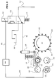
- FIG. 2 shows the feed and chopping device of the Harvester 10 again.
- the feeder is regarding the stream of harvested crop between the crop receiving device 20 and the chopper drum 22 are arranged.
- she consists in its basic structure of a pair of front Feed rollers 34, 36 and a pair of rear feed rollers 30, 32. Each roller of these pairs works with the other Roll together to remove the crop from the Harvesting device 20 for chopping drum 22 transport.
- Drive devices are provided that each of the feed rollers Set 30, 32, 34 and 36 in rotation.
- the respective Directions of rotation are indicated by arrows in FIG. 2.
- the upper feed rollers 32, 36 are relative to the lower feed rollers 30, 34 are arranged to be movable and pressed against the latter by spring force. Because of Clarity, and since they are known per se, the Storage of the upper feed rollers 32, 36 and the generation of the contact pressure springs are not used in Figure 2 drawn.
- the chopper is used with its circumference distributed knives 25 provided chopping drum 22 in Interaction with a shear bar 23.
- the Metal detection device has a sensor 62 that is arranged within the lower front feed roller 34.
- a sensor is, for example, from EP 0 324 253 A, DE 19912407, DE 2 552 805 A and those mentioned there References made known.
- the sensor 62 is a Line 66 connected to a controller 64, which in turn a device for locking the rear upper Feed roller 32 controls.
- the senor 62 responds, so that the controller 64 via line 66 with corresponding information is acted upon and caused by means of the device for Immediately lock the rear upper feed roller 32 to stop.
- the metal object is therefore not up to Chopper drum 22 transported so that the latter is not is damaged.
- the device for locking the rear upper Feed roller 32 includes a pawl 40 which is around a Pivot point 42 is rotatably mounted, and which with a cam 44th is provided.
- the cam 44 is set up to engage to reach a toothed wheel 38 which is on the axis of rotation of the arranged rear upper feed roller 32 and with the latter is rotatably connected.
- the fulcrum 42 is on the frame 12 of the Harvester 10 anchored.
- the pawl 40 is in their first (locked) position, as shown in Figure 2, the rear upper feed roller 32 cannot rotate; she is locked.
- the pawl 40 with the cam 44th raised and placed in a second (non-engaged) position can the rear upper feed roller 32 through her assigned drive devices are rotated.
- the position of the pawl 40 with the cam 44 is determined by a single-acting hydraulic cylinder 48 and a spring 46 controlled.
- the spring 46 is arranged such that it Pawl 40 spends in the second position as long as the Hydraulic cylinder 48 is not pressurized.
- the hydraulic cylinder 48 is through a first hydraulic oil line 50 connected to a valve 52.
- the valve 52 has two operating positions. In the shown in Figure 2 first position is through valve 52 the first hydraulic oil line 50 connected to a second hydraulic oil line 60, which is under operating pressure and (directly or indirectly) with an appropriate pressure vessel or one Hydraulic oil pump (charge pump or the like) is connected. The hydraulic cylinder 48 is therefore under operating pressure and spends the pawl 40 with the cam 44 in the first Position. In the second position of the valve 52 is the second Hydraulic oil line 60 shut off and the first hydraulic oil line 50 connected to a reservoir 56. In the second The position of the valve 52 is thus the hydraulic cylinder 48 depressurized and the spring 46 spends the pawl 40 with the Cam 44 in the second position so that the rear upper Feed roller 32 can rotate.
- the position of the valve 52 is determined by the controller 64 an electromagnetic actuator 58, which against the Force acts by a spring 54, controlled. Is that about one Line 68 adjusting drive 58 connected to controller 64 de-energized, the spring 54 moves the valve 52 into the first Position so that the pawl 40 is in its first position takes. If the adjustment drive 58 is controlled by the controller 64 powered, he spends the valve 52 in the second position, so that the hydraulic cylinder 48 is depressurized and the pawl 40 comes to the second position.
- the Control 64 is thus set up, the rear upper Lock the feed roller 32 when the sensor 62 responds. It is of course also possible, additionally or alternatively any other of the rear upper feed roller 32 Feed rollers 30, 34, 36 (or more of them) too lock.
- the advantage of using the hydraulic cylinder 48 lies in the achievable, relatively short response time. Besides, that is electrical circuit of the locking device designed such that in the event of a failure of the electrical power supply Pawl 40 automatically moved into its locked position is because the valve 52 in the absence of current through the Adjustment drive 58 by the action of spring 54 in the first Position is taken in which the hydraulic cylinder 48th is activated.
Landscapes
- Life Sciences & Earth Sciences (AREA)
- Environmental Sciences (AREA)
- Fluid-Pressure Circuits (AREA)
- Harvester Elements (AREA)
- Control Of Conveyors (AREA)
- Transmission Devices (AREA)
Abstract
Description
- Fig. 1
- eine Erntemaschine in Seitenansicht und in schematischer Darstellung und
- Fig. 2
- eine schematische Seitenansicht einer Einzugsund Häckselvorrichtung der Erntemaschine der Figur 1.
Claims (10)
- Vorrichtung zur Arretierung einer Ernteguttransporteinrichtung einer Erntemaschine (10), mit einem bewegbaren Sperrelement, das eingerichtet ist, eine erste Position, in der die Ernteguttransporteinrichtung arretiert ist, und eine zweite Position, in der die Ernteguttransporteinrichtung bewegbar ist, einzunehmen, und mit einer Einrichtung zur Bewegung des Sperrelements, dadurch gekennzeichnet, daß die Einrichtung zur Bewegung des Sperrelements einen Hydraulikzylinder (48) umfaßt.
- Vorrichtung nach Anspruch 1, dadurch gekennzeichnet, daß der Hydraulikzylinder (48) das Sperrelement in die erste Position verbringt, wenn er mit Druck beaufschlagt wird.
- Vorrichtung nach Anspruch 1 oder 2, dadurch gekennzeichnet, daß der Hydraulikzylinder (48) durch ein Ventil (52) mit einer Quelle für druckbeaufschlagtes Hydrauliköl verbindbar ist, und daß das Ventil (52) mit einem Verstellantrieb, insbesondere einem Elektromagnetantrieb (58), zwischen einer ersten Stellung, in der der Hydraulikzylinder (48) mit der Quelle verbunden ist, und einer zweiten Stellung, in der der Hydraulikzylinder (48) drucklos ist, bewegbar ist.
- Vorrichtung nach Anspruch 3, dadurch gekennzeichnet, daß das Ventil (52) in der ersten Stellung ist, wenn der Verstellantrieb nicht aktiviert ist.
- Vorrichtung nach Anspruch 4, gekennzeichnet durch eine Feder (54), die das Ventil (52) bei nicht aktiviertem Verstellantrieb in die erste Stellung verbringt.
- Vorrichtung nach einem der Ansprüche 1 bis 5, gekennzeichnet durch eine Feder (46), gegen die der Hydraulikzylinder (48) wirkt.
- Vorrichtung nach einem der vorhergehenden Ansprüche, dadurch gekennzeichnet, daß die Ernteguttransporteinrichtung eine Einzugswalze (32) umfaßt oder ist.
- Vorrichtung nach einem der vorhergehenden Ansprüche, dadurch gekennzeichnet, daß das Sperrelement eine Sperrklinke (40) umfaßt, die in Eingriff mit einem Element mit unrundem Querschnitt, insbesondere einem verzahnten Rad (38) oder Nockenrad, bringbar ist, das mittelbar oder unmittelbar drehfest mit der Ernteguttransporteinrichtung verbunden ist.
- Vorrichtung nach einem der vorhergehenden Ansprüche, gekennzeichnet durch eine Steuerung (64), die mit einem Sensor (62) für aufgenommenes unerwünschtes Material, insbesondere einem Metalldetektor, verbunden ist, und die zur Steuerung des Hydraulikzylinders (48) eingerichtet ist.
- Erntemaschine (10), insbesondere Feldhäcksler, mit einer Vorrichtung zur Arretierung der Ernteguttransporteinrichtung nach einem der vorhergehenden Ansprüche.
Applications Claiming Priority (3)
| Application Number | Priority Date | Filing Date | Title |
|---|---|---|---|
| DE19955901 | 1999-11-20 | ||
| DE19955901A DE19955901A1 (de) | 1999-11-20 | 1999-11-20 | Vorrichtung zur Arretierung einer Ernteguttransportvorrichtung |
| US09/651,180 US6397570B1 (en) | 1999-11-20 | 2000-08-30 | Stopping device for a crop transport mechanism |
Publications (2)
| Publication Number | Publication Date |
|---|---|
| EP1101398A1 true EP1101398A1 (de) | 2001-05-23 |
| EP1101398B1 EP1101398B1 (de) | 2004-07-28 |
Family
ID=26055598
Family Applications (1)
| Application Number | Title | Priority Date | Filing Date |
|---|---|---|---|
| EP00124772A Expired - Lifetime EP1101398B1 (de) | 1999-11-20 | 2000-11-14 | Vorrichtung zur Arretierung einer Ernteguttransporteinrichtung |
Country Status (4)
| Country | Link |
|---|---|
| US (1) | US6397570B1 (de) |
| EP (1) | EP1101398B1 (de) |
| CA (1) | CA2320379C (de) |
| DE (2) | DE19955901A1 (de) |
Cited By (1)
| Publication number | Priority date | Publication date | Assignee | Title |
|---|---|---|---|---|
| CN109526418A (zh) * | 2018-11-29 | 2019-03-29 | 徐浩 | 一种农作物秸秆回收综合利用方法 |
Families Citing this family (24)
| Publication number | Priority date | Publication date | Assignee | Title |
|---|---|---|---|---|
| GB0005178D0 (en) * | 2000-03-06 | 2000-04-26 | Ford New Holland Nv | Feeder controls for a forage harvester |
| US6584755B2 (en) * | 2001-08-14 | 2003-07-01 | Deere & Company | Apparatus for adjusting the spacing and/or the contact pressure between two rollers of a kernel processor |
| DE10207467A1 (de) * | 2002-02-22 | 2003-09-04 | Deere & Co | Antriebssystem einer Gutbearbeitungseinrichtung und einer Gutfördereinrichtung einer Erntemaschine |
| DE102004042620A1 (de) * | 2004-09-01 | 2006-03-23 | Claas Selbstfahrende Erntemaschinen Gmbh | Verfahren und Vorrichtung zur Einstellung der Empfindlichkeit einer Fremdkörpererkennungseinrichtung |
| DE102005023047A1 (de) * | 2005-05-13 | 2007-01-18 | Claas Selbstfahrende Erntemaschinen Gmbh | Einzugsorgansteuerung für landwirtschaftliche Arbeitsmaschine |
| DE102005056554A1 (de) * | 2005-11-25 | 2007-06-14 | Usines Claas France S.A.S., St. Rémy-Woippy | Aufsammeleinrichtung für landwirtschaftliche Erntemaschinen |
| DE102005059953A1 (de) * | 2005-12-15 | 2007-07-05 | Deere & Company, Moline | Feldhäcksler |
| DE102009002849A1 (de) | 2008-07-11 | 2010-01-14 | Deere & Company, Moline | Antriebssystem für einen Einzugsförderer einer Erntemaschine |
| GB2479566A (en) * | 2010-04-15 | 2011-10-19 | Agco Int Gmbh | Braking system for a rotating chopper drum of a forage harvester |
| US9136676B2 (en) * | 2012-01-26 | 2015-09-15 | Echostar Technologies L.L.C. | Electromagnetic tool for wire routing |
| CA2799093A1 (en) | 2012-12-18 | 2014-06-18 | Honey Bee Manufacturing Ltd. | Draper seal for crop header |
| US8833048B2 (en) | 2013-02-14 | 2014-09-16 | Honey Bee Manufacturing, Ltd. | Harvesting header bat with adjustably spaced quick release fingers |
| US10021823B2 (en) | 2013-12-30 | 2018-07-17 | Honey Bee Manufacturing Inc. | Harvesting header transport apparatus and method |
| US9901032B2 (en) | 2013-12-30 | 2018-02-27 | Honey Bee Manufacturing Ltd. | Harvesting header transport |
| CA2847456C (en) | 2014-03-26 | 2021-01-19 | Honey Bee Manufacturing Ltd. | Cam reel with complex bat path |
| US9844183B2 (en) | 2014-03-26 | 2017-12-19 | Honey Bee Manufacturing Ltd. | Cam reel with complex bat path |
| CA2853947A1 (en) | 2014-06-09 | 2015-12-09 | Honey Bee Manufacturing Ltd. | Harvesting header knife drive assemby |
| CA2876686C (en) | 2014-12-24 | 2021-01-19 | Honey Bee Manufacturing Ltd. | Reel system |
| US10462966B2 (en) | 2015-03-13 | 2019-11-05 | Honey Bee Manufacturing Ltd. | Controlling a positioning system for an agricultural implement |
| CA3062675C (en) | 2015-03-13 | 2021-03-23 | Honey Bee Manufacturing Ltd. | Controlling a positioning system for an agricultural implement |
| CA2937639C (en) | 2016-07-29 | 2026-04-14 | Honey Bee Manufacturing Ltd. | Header cutting system |
| CN112602452B (zh) * | 2020-12-04 | 2022-11-22 | 聊城杰德农林装备有限公司 | 一种具有粉碎功能的农用荒草割除机器人 |
| US12543651B2 (en) * | 2023-05-25 | 2026-02-10 | Cnh Industrial America Llc | Header conditioning roll system for an agricultural harvesting machine |
| CN117461482B (zh) * | 2023-12-27 | 2024-03-12 | 山西晋美羊畜牧科技有限公司 | 一种牧草收割用破碎机 |
Citations (8)
| Publication number | Priority date | Publication date | Assignee | Title |
|---|---|---|---|---|
| US3805497A (en) | 1971-05-14 | 1974-04-23 | Sperry Rand Corp | Vehicle protective system |
| DE2552805A1 (de) | 1974-12-04 | 1976-06-10 | Sperry Rand Corp | Vorrichtung zum erkennen von eisenhaltigem material in feldhaeckslern |
| US4296591A (en) * | 1980-10-01 | 1981-10-27 | Sperry Corporation | Damped apparatus for quick-stopping rotating members |
| EP0324253A2 (de) | 1988-01-13 | 1989-07-19 | FORD NEW HOLLAND, INC. (a Delaware corp.) | Metalldetektion in der Nähe von Eisengrenzflächen |
| SU1556575A2 (ru) * | 1988-03-24 | 1990-04-15 | Всесоюзный научно-исследовательский институт механизации сельского хозяйства | Устройство дл прокручивани рабочего органа уборочной машины при его забивании |
| EP0821871A2 (de) * | 1996-07-30 | 1998-02-04 | New Holland Belgium N.V. | Einzugsarretiervorrichtung in einer Erntemaschine |
| DE19742060A1 (de) * | 1997-09-24 | 1999-03-25 | Claas Selbstfahr Erntemasch | Fremdkörperrückführvorrichtung an Erntemaschinen o. dgl. |
| DE19912407A1 (de) | 1999-03-19 | 2000-09-21 | Deere & Co | Förderer mit Metalldetektionseinrichtung |
Family Cites Families (8)
| Publication number | Priority date | Publication date | Assignee | Title |
|---|---|---|---|---|
| DE3336603A1 (de) * | 1983-10-07 | 1985-04-25 | Klöckner-Humboldt-Deutz AG Zweigniederlassung Fahr, 7702 Gottmadingen | Vorrichtung zum rueckdrehen der einzugsschnecke eines maehdreschers |
| DE3344043A1 (de) * | 1983-12-06 | 1985-06-13 | Claas Saulgau GmbH, 7968 Saulgau | Schaltbare ueberlastkupplung |
| US4639666A (en) * | 1984-08-27 | 1987-01-27 | New Holland, Inc. | Metal detector sensitivity adjustment and test assembly |
| US4854113A (en) * | 1987-12-29 | 1989-08-08 | Ford New Holland, Inc. | Digital noise cancellation in a metal detector |
| US4805385A (en) * | 1987-12-29 | 1989-02-21 | Ford New Holland, Inc. | Variable sensitivity metal detection system |
| DE4314427C2 (de) * | 1993-05-03 | 2002-02-21 | Stihl Maschf Andreas | Freischneidegerät |
| DE19632977B4 (de) * | 1996-08-16 | 2009-04-02 | Claas Kgaa Mbh | Vorrichtung und Verfahren zur Einzugssteuerung eines Feldhäckslers |
| DE19854562A1 (de) * | 1998-11-26 | 2000-05-31 | Claas Saulgau Gmbh | Einrichtung zur Überwachung der Einzugsbaugruppe einer landwirtschaftlichen Erntemaschine |
-
1999
- 1999-11-20 DE DE19955901A patent/DE19955901A1/de not_active Withdrawn
-
2000
- 2000-08-30 US US09/651,180 patent/US6397570B1/en not_active Expired - Fee Related
- 2000-09-21 CA CA002320379A patent/CA2320379C/en not_active Expired - Fee Related
- 2000-11-14 EP EP00124772A patent/EP1101398B1/de not_active Expired - Lifetime
- 2000-11-14 DE DE50007192T patent/DE50007192D1/de not_active Expired - Lifetime
Patent Citations (8)
| Publication number | Priority date | Publication date | Assignee | Title |
|---|---|---|---|---|
| US3805497A (en) | 1971-05-14 | 1974-04-23 | Sperry Rand Corp | Vehicle protective system |
| DE2552805A1 (de) | 1974-12-04 | 1976-06-10 | Sperry Rand Corp | Vorrichtung zum erkennen von eisenhaltigem material in feldhaeckslern |
| US4296591A (en) * | 1980-10-01 | 1981-10-27 | Sperry Corporation | Damped apparatus for quick-stopping rotating members |
| EP0324253A2 (de) | 1988-01-13 | 1989-07-19 | FORD NEW HOLLAND, INC. (a Delaware corp.) | Metalldetektion in der Nähe von Eisengrenzflächen |
| SU1556575A2 (ru) * | 1988-03-24 | 1990-04-15 | Всесоюзный научно-исследовательский институт механизации сельского хозяйства | Устройство дл прокручивани рабочего органа уборочной машины при его забивании |
| EP0821871A2 (de) * | 1996-07-30 | 1998-02-04 | New Holland Belgium N.V. | Einzugsarretiervorrichtung in einer Erntemaschine |
| DE19742060A1 (de) * | 1997-09-24 | 1999-03-25 | Claas Selbstfahr Erntemasch | Fremdkörperrückführvorrichtung an Erntemaschinen o. dgl. |
| DE19912407A1 (de) | 1999-03-19 | 2000-09-21 | Deere & Co | Förderer mit Metalldetektionseinrichtung |
Non-Patent Citations (1)
| Title |
|---|
| DATABASE WPI Section PQ Week 199048, Derwent World Patents Index; Class P12, AN 1990-359982, XP002157574 * |
Cited By (2)
| Publication number | Priority date | Publication date | Assignee | Title |
|---|---|---|---|---|
| CN109526418A (zh) * | 2018-11-29 | 2019-03-29 | 徐浩 | 一种农作物秸秆回收综合利用方法 |
| CN109526418B (zh) * | 2018-11-29 | 2021-12-17 | 江苏河海给排水成套设备有限公司 | 一种农作物秸秆回收综合利用方法 |
Also Published As
| Publication number | Publication date |
|---|---|
| EP1101398B1 (de) | 2004-07-28 |
| US6397570B1 (en) | 2002-06-04 |
| CA2320379A1 (en) | 2001-05-20 |
| DE50007192D1 (de) | 2004-09-02 |
| CA2320379C (en) | 2004-03-02 |
| DE19955901A1 (de) | 2001-05-23 |
Similar Documents
| Publication | Publication Date | Title |
|---|---|---|
| EP1101398B1 (de) | Vorrichtung zur Arretierung einer Ernteguttransporteinrichtung | |
| EP1731983B1 (de) | Landwirtschaftliche Arbeitsmaschine mit einer Austrageinrichtung und einem Kollisionssensor | |
| DE602004004500T2 (de) | Gewächsbearbeitungsvorrichtung | |
| EP1004234B1 (de) | Einrichtung zur Überwachung der Einzugsbaugruppe einer landwirtschaftlichen Erntemaschine | |
| EP1997366B1 (de) | Landwirtschaftliche Erntemaschine mit einer Fremdkörpererkennungsvorrichtung | |
| EP2067399B1 (de) | Anordnung zur Verstellung der Position einer Aufnehmertrommel und eines Niederhalters einer landwirtschaftlichen Erntemaschine | |
| DE102009045044B4 (de) | Kombination aus einem landwirtschaftlichen Gerät und einem Träger- oder Zugfahrzeug mit einem Sensor zur Erfassung einer Gefahrensituation und einer automatischen Abschaltung der Zapfwelle | |
| DE2857815C2 (de) | Erntemaschine | |
| DE102004022801A1 (de) | Rundballenpresse | |
| EP1400162B1 (de) | Sicherheitseinrichtung einer Erntemaschine | |
| DE2910139A1 (de) | Selbstfahrender maehdrescher mit automatischer maehtisch-hoeheneinstellung | |
| DE69711509T2 (de) | Einzugsarretiervorrichtung in einer Erntemaschine | |
| EP3804495B1 (de) | Schneidwerk mit sicherung für eine höhenverstellbare haspel | |
| EP0077474B1 (de) | Schneidwerk für Selbstladeerntewagen | |
| EP1046333A1 (de) | Erntemaschine | |
| EP0714592A2 (de) | Steuersystem zur Lageeinstellung von Anhängevorrichtungen | |
| EP3449718B1 (de) | Wiegeeinrichtung und erntebergungsgerät | |
| EP2742794B1 (de) | Landwirtschaftliche Erntemaschine und Verfahren zum Warten einer solchen Erntemaschine | |
| DE102014016498B4 (de) | Verfahren und Steuereinrichtung zum Betreiben einer Balleneinwickelvorrichtung | |
| DE19847891A1 (de) | Steuerung für Vorsatzgerät | |
| EP3900517A1 (de) | Rundballenpresse und verfahren zum betrieb einer rundballenpresse | |
| EP3706546B1 (de) | Pick-up mit metalldetektor | |
| EP1736043A2 (de) | Steuerung für Kreiselschwader und Mähwerke als landwirtschaftliche Arbeitsmaschinen | |
| EP3729950B1 (de) | Raffeinrichtung zum wahlweisen seitlichen zusammenführen einer folie zum umwickeln eines ballens | |
| EP0479190B1 (de) | Fahrbare Erntemaschine, insbesondere Rundballenpresse |
Legal Events
| Date | Code | Title | Description |
|---|---|---|---|
| PUAI | Public reference made under article 153(3) epc to a published international application that has entered the european phase |
Free format text: ORIGINAL CODE: 0009012 |
|
| AK | Designated contracting states |
Kind code of ref document: A1 Designated state(s): BE DE DK |
|
| AX | Request for extension of the european patent |
Free format text: AL;LT;LV;MK;RO;SI |
|
| 17P | Request for examination filed |
Effective date: 20011123 |
|
| AKX | Designation fees paid |
Free format text: BE DE DK |
|
| 17Q | First examination report despatched |
Effective date: 20030704 |
|
| GRAP | Despatch of communication of intention to grant a patent |
Free format text: ORIGINAL CODE: EPIDOSNIGR1 |
|
| GRAS | Grant fee paid |
Free format text: ORIGINAL CODE: EPIDOSNIGR3 |
|
| GRAA | (expected) grant |
Free format text: ORIGINAL CODE: 0009210 |
|
| AK | Designated contracting states |
Kind code of ref document: B1 Designated state(s): BE DE DK |
|
| REF | Corresponds to: |
Ref document number: 50007192 Country of ref document: DE Date of ref document: 20040902 Kind code of ref document: P |
|
| PG25 | Lapsed in a contracting state [announced via postgrant information from national office to epo] |
Ref country code: DK Free format text: LAPSE BECAUSE OF FAILURE TO SUBMIT A TRANSLATION OF THE DESCRIPTION OR TO PAY THE FEE WITHIN THE PRESCRIBED TIME-LIMIT Effective date: 20041028 |
|
| PLBE | No opposition filed within time limit |
Free format text: ORIGINAL CODE: 0009261 |
|
| STAA | Information on the status of an ep patent application or granted ep patent |
Free format text: STATUS: NO OPPOSITION FILED WITHIN TIME LIMIT |
|
| 26N | No opposition filed |
Effective date: 20050429 |
|
| PGFP | Annual fee paid to national office [announced via postgrant information from national office to epo] |
Ref country code: BE Payment date: 20091224 Year of fee payment: 10 |
|
| BERE | Be: lapsed |
Owner name: *DEERE & CY Effective date: 20101130 |
|
| PG25 | Lapsed in a contracting state [announced via postgrant information from national office to epo] |
Ref country code: BE Free format text: LAPSE BECAUSE OF NON-PAYMENT OF DUE FEES Effective date: 20101130 |
|
| PGFP | Annual fee paid to national office [announced via postgrant information from national office to epo] |
Ref country code: DE Payment date: 20191130 Year of fee payment: 20 |
|
| REG | Reference to a national code |
Ref country code: DE Ref legal event code: R071 Ref document number: 50007192 Country of ref document: DE |