EP1100314B2 - An apparatus for automatically milking an animal - Google Patents
An apparatus for automatically milking an animal Download PDFInfo
- Publication number
- EP1100314B2 EP1100314B2 EP99943530A EP99943530A EP1100314B2 EP 1100314 B2 EP1100314 B2 EP 1100314B2 EP 99943530 A EP99943530 A EP 99943530A EP 99943530 A EP99943530 A EP 99943530A EP 1100314 B2 EP1100314 B2 EP 1100314B2
- Authority
- EP
- European Patent Office
- Prior art keywords
- teatcup
- teatcups
- teat
- movable arm
- end portion
- Prior art date
- Legal status (The legal status is an assumption and is not a legal conclusion. Google has not performed a legal analysis and makes no representation as to the accuracy of the status listed.)
- Expired - Lifetime
Links
Images


Classifications
-
- A—HUMAN NECESSITIES
- A01—AGRICULTURE; FORESTRY; ANIMAL HUSBANDRY; HUNTING; TRAPPING; FISHING
- A01J—MANUFACTURE OF DAIRY PRODUCTS
- A01J5/00—Milking machines or devices
- A01J5/017—Automatic attaching or detaching of clusters
- A01J5/0175—Attaching of clusters
Definitions
- the present invention relates to an apparatus for automatically milking an animal, comprising a plurality ofteatcups each having a teat entrance end, and a movable arm for moving said teatcups towards a teat of an animal to be milked and attaching it thereto.
- FIG. 5C discloses in one embodiment (Fig. 5C) an apparatus for automatic milking which holds a magazine or clip of four teatcups, which is manoeuvred so as to place one of the teatcups below the intended cow teat, whereupon a dedicated lifting device is actuated, lifting the individual teatcup until suction attaches it to its teat.
- An object of the invention is to improve the success rate of teatcup attachment and make possible, with very simple and reliable means, reattachment of inadvertently detached teatcups, without the necessity of removing any other teatcups first.
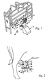
- FIG. 1 shows robot milking stall 2 provided with a milking robot 4 having a movable arm in form of a robot arm 6 with a gripping means 7 adapted to grip one teatcup.
- a teatcup rack 8 is provided with four teatcups 10, 12, 14, 16, each teatcup having a teat entrance end 17a and a milk exit end 17b.
- two teatcups 10, 12 thereof are of the same or similar length, while two other teatcups 14, 16 - of the same or similar length - are shorter than the other two teatcups 10, 12.
- An udder 18 of a cow has rear teats 20, 22, and front teats 24, 26.
- the robot arm shown in figure 1 is intended to bring the teatcups 10, 12, 14, 16 under the belly and between the front and rear legs of a cow.
- the teatcups 10, 12 are to be attached to the rear teats 20, 22, whereas the teatcups 14, 16 are to be attached to the front teats 24, 26, for reasons that will be apparent below.
- An image capturing device 28 such as a digital video camera is arranged on the side of the stall 2, for viewing at least the udder 18 of the cow, before, during and/or after teatcup attachment.
- the robot arm 6 is provided with an angular end portion 30, which is provided with a teat location means 32, in the form of a digital video camera and/or a laser sensor, and the gripping means 7. This allows for a movement of a teatcup towards the rear of the cow, while viewing in the same direction.
- the angular end portion may be e.g. perpendicular
- one of the longer teatcups 10 is attached to a rear teat 20. Then, the other one of the longer teatcups 12 is attached to the other rear teat 22. Subsequently, one of the two shorter teatcups 14 is attached to a front teat 24. Thereafter the other one of the shorter teatcups 16 is attached to the other front teat 26.
- one of the longer teatcups 10 is attached to a rear teat 20. Then, one of the two shorter teatcups 14 is attached to a front teat 24. Then, the other one of the longer teatcups 12 is attached to the other rear teat 22 and thereafter the other one of the shorter teatcups 16 is attached to the other front teat 26.
- Figure 2 shows a situation where one of the longer teatcups 10 for some reason has fallen off one of the rear teats e.g. 20 and therefore (or for any other reason) has to be re-attached thereonto, while a shorter teatcup e.g. 14 is still attached to a front teat 24 in front of that rear teat 20.
- the longer teatcup is allowed to be re-attached to the rear teat 20 without having to first detach the teatcup 14, as the teat robot arm end portion 30 will be able to pass the short teatcup 14.
- the robot arm 6 should be adapted to move each teatcup between the rear legs of the cow.
- Such a robot arm 6 should preferably be straight, rather than having an angular end portion 30.
- the longer teatcups 10, 12 are in that case to be attached to the front teats 24, 26 and the shorter teatcups 14, 16 to the rear teats 20, 22.
- a further image capturing device 28 may be arranged on the opposite side of the stall 2 for viewing at least the udder 18 from that side.
- FIG 3A illustrates a second arrangement, in which the teatcup rack 8 in figure 1 is substituted by a teatcup supply means 40 hingedly arranged on the robot arm 6.
- the teatcup supply means 40 constituting said movable arm is allowed to rotate about the hinge by means of a pneumatic or hydraulic cylinder 41.
- the teatcup supply means 40 is provided with a pair of parallel elongated members 42, 44, defining an intermediate elongated space 46.
- the members 42, 44 and the space 46 have a fork like configuration, i.e. the elongated space 46 has an open end 47.
- the cylinder 41 may be substituted by an electric step motor.
- the members 42, 44 are furthermore formed to comprise a lower portion 48, an upper portion 49 and an intermediate portion 50.
- the upper portion 49 is adapted to house one teatcup 52
- the lower portion 48 is adapted to house a row of three teatcups 54, 56, 58, the four teatcups 52, 54, 56, 58 preferably - but not necessarily - being of the same length.
- the teatcups 52, 54, 56, 58 are provided with an annular flange member 59, which rests on the elongated members 42, 44, such that the teatcups are kept in the elongated space 46.
- a driving means 59b in the form of a spring, an electric motor or a hydraulic or pneumatic cylinder, is adapted to push the teatcups towards the upper part 49.
- the different levels of the teat supply means 40 allows for a re-attachment of a teatcup which has fallen off a teat without having to first detach a teatcup attached to a teat in front of the other teat, as the portion 49 will be able to pass the already attached teatcup.
- FIG 3B illustrates a stall 2 provided with a milking robot 4 with the robot arm 6 and the teatcup supply means 40 shown in figure 3A .
- the robot arm 6 retracts the teatcup supply means 40 horizontally, away from the attached teatcup, which slides off the upper portion 49 via the open end 47.
- the conveying means 59a then pushes the three teatcups 54, 56, 58 on the lower portion 48 towards the upper portion 49, which results in that the teatcup 54 slides to the upper portion 49 via the intermediate portion 50.
- the conveying means is retracted again, if needed, such that the two remaining teatcups 56, 58, are kept on the lower portion 48.
- the sequence is repeated until all the teatcups have been attached to the respective teats.
- Figure 3C illustrates the teatcup supply means 40 shown in figure 3A arranged as a service arm, which is hingedly arranged about a vertical axis A, and movable in a horizontal plane about the hinge to suitable positions (cf. the broken lines) by means of a not shown electric step motor or hydraulic or pneumatic cylinder, in the same manner as shown in figure 3A .
- the movement of service arm is controlled by a computer, which is associated with the teat location means 32 on the robot arm.
- a separate camera as the one shown in figure 1 , (reference numeral 28) may be used to view the movement of the service arm.
- the computer will then, of course, act in response to that camera, or in combination with the teat location means 32.
- the service arm supplies a teatcup at the udder 18.
- the teatcup is gripped by the gripper 7 of the robot arm 6, which has a straight end portion 30.
- the teatcups are simply slid off the end portion 47 by the robot arm 6 and attached to a suitable teat (cf. the embodiment according to figures 3A and 3B ).
- the next teatcup is slid to the upper portion 49 and the gripper 7 grips it - and also the subsequent teatcups - at substantially the same place in space as it gripped the previous teatcup.
- the need for moving the robot arm when fetching the teatcups is accordingly enormous reduced, which results in a quicker and safer teatcup attachment.
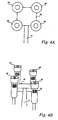
- FIGS 4A - 4C show an embodiment of the present invention, in which four teatcups 60, 62, 64, 66 are disengagably disposed in a vertically displaced relationship on the end portion 30.
- Each of the teatcups is provided with a bar code 70, for allowing identification thereof by means of a teat location means 32 in the form of a laser sensor (cf. figure 3C ).
- the laser sensor is of the kind described in detail in WO 97/15900 , and is furthermore able to read bar codes.
- the teatcup 60 is to be attached to the rear teat 20 of the udder 18.
- the laser sensor 32 locates the position of the teat 20 and furthermore establishes the identity of the teatcup 60. It is desirable that none of the other teatcups is allowed to be attached to that teat, as it would cause troublesome further teacup attachment.
- the teatcup 60 When the teatcup 60 has been attached to the teat 20, the teatcup is released from the end portion 30. The teatcup 62 is then ready to be attached to the teat 22.
- the teatcups are individually detached from the relevant teat and returned to the end portion 30 of the robot arm 6 by means of e.g. a cord (not shown).
- the attachment of the teatcups 60, 62, 64, 66 to the end portion 30 is performed by means of electromagnets (not shown).
Landscapes
- Life Sciences & Earth Sciences (AREA)
- Animal Husbandry (AREA)
- Environmental Sciences (AREA)
- Manipulator (AREA)
- Housing For Livestock And Birds (AREA)
- Toys (AREA)
- Catching Or Destruction (AREA)
Abstract
Description
- The present invention relates to an apparatus for automatically milking an animal, comprising a plurality ofteatcups each having a teat entrance end, and a movable arm for moving said teatcups towards a teat of an animal to be milked and attaching it thereto.
- An apparatus of this kind is known from
WO 90/07268 - A further apparatus of this type is described in
DE A1 4113700 , which discloses in one embodiment (Fig. 5C) an apparatus for automatic milking which holds a magazine or clip of four teatcups, which is manoeuvred so as to place one of the teatcups below the intended cow teat, whereupon a dedicated lifting device is actuated, lifting the individual teatcup until suction attaches it to its teat. - An object of the invention is to improve the success rate of teatcup attachment and make possible, with very simple and reliable means, reattachment of inadvertently detached teatcups, without the necessity of removing any other teatcups first.
- This has been obtained by an apparatus according to claim 1.
-
-
Figure 1 is a perspective view of an animal stall provided with a milking robot. -
Figure 2 illustrates a first arrangement. -
Figures 3A to 3C illustrate a second arrangement. -
Figures 4A to 4C illustrate an embodiment of the invention. -
Figure 1 showsrobot milking stall 2 provided with a milking robot 4 having a movable arm in form of a robot arm 6 with a gripping means 7 adapted to grip one teatcup. A teatcup rack 8 is provided with fourteatcups teat entrance end 17a and amilk exit end 17b. According to a first embodiment of the invention, twoteatcups other teatcups 14, 16 - of the same or similar length - are shorter than the other twoteatcups - An
udder 18 of a cow hasrear teats front teats figure 1 is intended to bring theteatcups teatcups rear teats teatcups front teats - An
image capturing device 28, such as a digital video camera is arranged on the side of thestall 2, for viewing at least theudder 18 of the cow, before, during and/or after teatcup attachment. - The robot arm 6 is provided with an
angular end portion 30, which is provided with a teat location means 32, in the form of a digital video camera and/or a laser sensor, and the gripping means 7. This allows for a movement of a teatcup towards the rear of the cow, while viewing in the same direction. The angular end portion may be e.g. perpendicular - After optional cleaning of the teats, one of the
longer teatcups 10 is attached to arear teat 20. Then, the other one of thelonger teatcups 12 is attached to the otherrear teat 22. Subsequently, one of the twoshorter teatcups 14 is attached to afront teat 24. Thereafter the other one of theshorter teatcups 16 is attached to the otherfront teat 26. - Alternatively, one of the
longer teatcups 10 is attached to arear teat 20. Then, one of the twoshorter teatcups 14 is attached to afront teat 24. Then, the other one of thelonger teatcups 12 is attached to the otherrear teat 22 and thereafter the other one of theshorter teatcups 16 is attached to the otherfront teat 26. -
Figure 2 shows a situation where one of thelonger teatcups 10 for some reason has fallen off one of the rear teats e.g. 20 and therefore (or for any other reason) has to be re-attached thereonto, while a shorter teatcup e.g. 14 is still attached to afront teat 24 in front of thatrear teat 20. In this case, the longer teatcup is allowed to be re-attached to therear teat 20 without having to first detach theteatcup 14, as the teat robotarm end portion 30 will be able to pass theshort teatcup 14. - It should be noted that it would be possible to arrange the milking robot 4 behind the
stall 2, in which case the robot arm 6 should be adapted to move each teatcup between the rear legs of the cow. Such a robot arm 6 should preferably be straight, rather than having anangular end portion 30. Thelonger teatcups front teats shorter teatcups rear teats - A further
image capturing device 28 may be arranged on the opposite side of thestall 2 for viewing at least theudder 18 from that side. -
Figure 3A illustrates a second arrangement, in which the teatcup rack 8 infigure 1 is substituted by a teatcup supply means 40 hingedly arranged on the robot arm 6. The teatcup supply means 40 constituting said movable arm is allowed to rotate about the hinge by means of a pneumatic orhydraulic cylinder 41. The teatcup supply means 40 is provided with a pair of parallelelongated members 42, 44, defining an intermediateelongated space 46. Themembers 42, 44 and thespace 46 have a fork like configuration, i.e. theelongated space 46 has an open end 47. It should be noted that thecylinder 41 may be substituted by an electric step motor. - The
members 42, 44 are furthermore formed to comprise alower portion 48, an upper portion 49 and anintermediate portion 50. The upper portion 49 is adapted to house oneteatcup 52, whereas thelower portion 48 is adapted to house a row of threeteatcups teatcups teatcups annular flange member 59, which rests on theelongated members 42, 44, such that the teatcups are kept in theelongated space 46. - A conveying means 59a driven by a driving means 59b, in the form of a spring, an electric motor or a hydraulic or pneumatic cylinder, is adapted to push the teatcups towards the upper part 49. When the
teatcup 52 is removed from the upper portion 49 theteatcups intermediate portion 50. - The different levels of the teat supply means 40 allows for a re-attachment of a teatcup which has fallen off a teat without having to first detach a teatcup attached to a teat in front of the other teat, as the portion 49 will be able to pass the already attached teatcup.
- If an attached teatcup still disturbs the movement of the teatcup supply means 40, it is simply turned about the hinge by means of the
cylinder 41, until the attached teatcup can be passed. -
Figure 3B illustrates astall 2 provided with a milking robot 4 with the robot arm 6 and the teatcup supply means 40 shown infigure 3A . When theteatcup 52 has been attached to a teat, the robot arm 6 retracts the teatcup supply means 40 horizontally, away from the attached teatcup, which slides off the upper portion 49 via the open end 47. The conveying means 59a then pushes the threeteatcups lower portion 48 towards the upper portion 49, which results in that theteatcup 54 slides to the upper portion 49 via the intermediate portion 50.The conveying means is retracted again, if needed, such that the two remainingteatcups lower portion 48. - The sequence is repeated until all the teatcups have been attached to the respective teats.
-
Figure 3C illustrates the teatcup supply means 40 shown infigure 3A arranged as a service arm, which is hingedly arranged about a vertical axis A, and movable in a horizontal plane about the hinge to suitable positions (cf. the broken lines) by means of a not shown electric step motor or hydraulic or pneumatic cylinder, in the same manner as shown infigure 3A . The movement of service arm is controlled by a computer, which is associated with the teat location means 32 on the robot arm. Of course, a separate camera, as the one shown infigure 1 , (reference numeral 28) may be used to view the movement of the service arm. The computer will then, of course, act in response to that camera, or in combination with the teat location means 32. - During teatcup attachment, the service arm supplies a teatcup at the
udder 18. The teatcup is gripped by the gripper 7 of the robot arm 6, which has astraight end portion 30. The teatcups are simply slid off the end portion 47 by the robot arm 6 and attached to a suitable teat (cf. the embodiment according tofigures 3A and 3B ). The next teatcup is slid to the upper portion 49 and the gripper 7 grips it - and also the subsequent teatcups - at substantially the same place in space as it gripped the previous teatcup. The need for moving the robot arm when fetching the teatcups is accordingly immensely reduced, which results in a quicker and safer teatcup attachment. -
Figures 4A - 4C show an embodiment of the present invention, in which fourteatcups end portion 30. Each of the teatcups is provided with abar code 70, for allowing identification thereof by means of a teat location means 32 in the form of a laser sensor (cf.figure 3C ). The laser sensor is of the kind described in detail inWO 97/15900 - The
teatcup 60 is to be attached to therear teat 20 of theudder 18. For this purpose, thelaser sensor 32 locates the position of theteat 20 and furthermore establishes the identity of theteatcup 60. It is desirable that none of the other teatcups is allowed to be attached to that teat, as it would cause troublesome further teacup attachment. - When the
teatcup 60 has been attached to theteat 20, the teatcup is released from theend portion 30. Theteatcup 62 is then ready to be attached to theteat 22. - After performed milking the teatcups are individually detached from the relevant teat and returned to the
end portion 30 of the robot arm 6 by means of e.g. a cord (not shown). - The attachment of the
teatcups end portion 30 is performed by means of electromagnets (not shown).
Claims (9)
- An apparatus for automatically milking an animal, comprising a plurality of teatcups (60, 62, 64, 66) each having a teat entrance end (17a), and a movable arm (6) for moving said teatcups towards a teat of an animal to be milked and attaching it thereto, wherein the teat entrance end (17a) of at least one of said teatcups is arranged, while being moved by said movable arm (6) towards said teat, to be held in relation to said movable arm (6) at a level which is different from that of the teat entrance end (17a) of a further one of said teatcups, when held in relation to said movable arm, whereina) said movable arm (6) is provided with an end portion (30) for holding a plurality of teatcups (60, 62, 64, 66) wherein said teatcup is held at a level, which is different from that of said further teatcup held by said end portion (30),b) said at least one teatcup (60) and said further teatcup (62, 64, 66) are arranged to co-operate with a connection means of said end portion (30) in such a way, that they are held at different levels in relation to said end portion andc) said connection means includes electromagnets for attaching the teatcups to said end portion.
- An apparatus according to claim 1, wherein said at least one teatcup (60) and said further teatcup (62,64,66) are movable away from said end portion (30), independently from one another.
- An apparatus according to anyone of the preceding claims, wherein said at least one teatcup and said movable arm are provided with an identification means (32,70) for allowing establishment of the identity of said at least one teatcup.
- An apparatus according to claim 3, wherein said at least one teatcup is provided with bar code (70), and said movable arm is provided with a laser reader (32) for reading said bar code (70).
- An apparatus according to anyone of the preceding claims, wherein the teat entrance end (17a) of said at least one teatcup is arranged at a higher level that the teat entrance end of the further teatcup, as seen in a vertical plane.
- An apparatus according to anyone of claims 1 to 5, wherein said movable arm is a robot arm (6).
- An apparatus according to claim 6, wherein said robot arm is provided with laser sensor (32).
- An apparatus according to claim 7, wherein said laser sensor (32) comprises a laser transmitter for forming a line, such as a scanning laser beam or a stable or scanning laser plane, and a laser reader, such as an image capturing device.
- An apparatus according to claim 8, wherein said laser reader (32) is adapted to read bar codes (70).
Priority Applications (1)
| Application Number | Priority Date | Filing Date | Title |
|---|---|---|---|
| DE69915839T DE69915839T3 (en) | 1998-07-24 | 1999-07-23 | DEVICE FOR THE AUTOMATIC MILKING OF ANIMALS |
Applications Claiming Priority (3)
| Application Number | Priority Date | Filing Date | Title |
|---|---|---|---|
| SE9802611A SE517285C2 (en) | 1998-07-24 | 1998-07-24 | Apparatus for automatic milking of an animal |
| SE9802611 | 1998-07-24 | ||
| PCT/SE1999/001304 WO2000004766A1 (en) | 1998-07-24 | 1999-07-23 | An apparatus for automatically milking an animal |
Publications (3)
| Publication Number | Publication Date |
|---|---|
| EP1100314A1 EP1100314A1 (en) | 2001-05-23 |
| EP1100314B1 EP1100314B1 (en) | 2004-03-24 |
| EP1100314B2 true EP1100314B2 (en) | 2011-10-19 |
Family
ID=20412149
Family Applications (1)
| Application Number | Title | Priority Date | Filing Date |
|---|---|---|---|
| EP99943530A Expired - Lifetime EP1100314B2 (en) | 1998-07-24 | 1999-07-23 | An apparatus for automatically milking an animal |
Country Status (9)
| Country | Link |
|---|---|
| US (1) | US6575116B1 (en) |
| EP (1) | EP1100314B2 (en) |
| JP (1) | JP2002521009A (en) |
| AU (1) | AU5660599A (en) |
| CA (1) | CA2338732C (en) |
| DE (1) | DE69915839T3 (en) |
| IL (1) | IL140941A0 (en) |
| SE (1) | SE517285C2 (en) |
| WO (1) | WO2000004766A1 (en) |
Families Citing this family (16)
| Publication number | Priority date | Publication date | Assignee | Title |
|---|---|---|---|---|
| US20080248466A1 (en) * | 2004-07-30 | 2008-10-09 | Tm Bioscience Pgx Inc. | Method Of Detecting Mutations In The Gene Encoding Cytochrome P450-2C19 |
| SE529127C2 (en) * | 2005-09-02 | 2007-05-08 | Delaval Holding Ab | Detection arrangement and method of magnetic gripping device |
| NL1032429C2 (en) * | 2006-09-05 | 2008-03-06 | Maasland Nv | Method for controlling milking device, as well as software program for and device with this method. |
| SE531487C2 (en) | 2007-03-23 | 2009-04-21 | Delaval Holding Ab | A teat cup handling device and a teat cup storage device |
| NL1034502C2 (en) * | 2007-10-12 | 2009-04-15 | Lely Patent Nv | Milking device. |
| EP2060172B1 (en) * | 2007-11-16 | 2014-12-17 | DeLaval Holding AB | Apparatus and method for positioning a teat cup |
| WO2010007007A1 (en) * | 2008-07-17 | 2010-01-21 | Delaval Holding Ab | A system and method for automatically obtaining a milk sample and performing cleaning |
| WO2010060693A1 (en) * | 2008-11-26 | 2010-06-03 | Delaval Holding Ab | Handling of teat cups |
| AU2010288660A1 (en) * | 2009-08-26 | 2012-02-16 | Delaval Holding Ab | Milking robot and method for teat cup attachment |
| RU2551565C2 (en) | 2010-01-29 | 2015-05-27 | Геа Хоул Инк. | Rotary milking station, kit for its mounting and methods of its mounting and operation |
| CA2799479C (en) | 2010-06-17 | 2018-06-19 | Delaval Holding Ab | A gripper, a milking robot and a milking arrangement |
| EP2632248A1 (en) * | 2010-10-26 | 2013-09-04 | DeLaval Holding AB | A control system for at least one flexible tubular element connected to a cup-shaped member |
| EP2934098B2 (en) * | 2012-12-19 | 2024-05-22 | DeLaval Holding AB | Milking arrangement, set of exchangeable expendable parts and method for a milking arrangement |
| NL2010406C2 (en) * | 2013-03-07 | 2014-09-10 | Rotec Engineering B V | GRIPER FOR APPLYING MILK CUPLES TO ANIMAL TO BE MILKED, ROBOT ARM AND MILK MACHINE PROVIDED THEREOF, AND METHOD FOR THIS. |
| NL2015970B1 (en) * | 2015-12-16 | 2017-06-30 | Lely Patent Nv | Milking establishment |
| NL2026125B1 (en) * | 2020-07-23 | 2022-03-28 | Lely Patent Nv | Robotic milking device |
Citations (4)
| Publication number | Priority date | Publication date | Assignee | Title |
|---|---|---|---|---|
| EP0300582A1 (en) † | 1987-07-23 | 1989-01-25 | C. van der Lely N.V. | An implement for and a method of milking an animal |
| EP0302559A1 (en) † | 1987-08-05 | 1989-02-08 | Gascoigne-Melotte B.V. | Milking machine |
| EP0360354A1 (en) † | 1988-09-21 | 1990-03-28 | C. van der Lely N.V. | An implement for milking an animal as well as a method of connecting teat cups to the teats of same |
| NL9200093A (en) † | 1992-01-17 | 1993-08-16 | Lely Nv C Van Der | Automatic control and monitoring system for milking parlour |
Family Cites Families (18)
| Publication number | Priority date | Publication date | Assignee | Title |
|---|---|---|---|---|
| NL193648C (en) * | 1986-08-27 | 2000-06-06 | Lely Nv C Van Der | Device for milking animals. |
| DE4113700A1 (en) | 1991-04-26 | 1992-10-29 | Dieter Dipl Ing Schillingmann | Automatic milking using milking robot - using stored data to position milking cups for each individual cow |
| NL9101064A (en) | 1991-06-20 | 1993-01-18 | Gascoigne Melotte Bv | DEVICE FOR APPLYING RESPECTIVELY REMOVAL OF A BOTTLE BUCKET SET FROM ANIMALS. |
| NL9200419A (en) | 1992-03-06 | 1993-10-01 | Lely Nv C Van Der | DEVICE FOR MILKING ANIMALS. |
| NL9200639A (en) | 1992-04-06 | 1993-11-01 | Lely Nv C Van Der | DEVICE FOR AUTOMATIC MILKING OF ANIMALS. |
| NL9301751A (en) | 1993-10-11 | 1995-05-01 | Texas Industries Inc | Device for automatic milking of animals. |
| NL9401113A (en) * | 1994-07-04 | 1996-02-01 | Maasland Nv | Construction with a device for automatic milking of animals. |
| NL9401801A (en) * | 1994-08-23 | 1996-04-01 | Maasland Nv | Construction with a device for milking animals. |
| NL1000010C2 (en) * | 1995-04-03 | 1996-10-04 | Maasland Nv | Method for positioning means required for automatic milking under the udder of an animal, as well as a device in which this method can be applied. |
| US6116188A (en) * | 1996-04-24 | 2000-09-12 | Van Der Lely; Cornelis | Method of milking animals |
| DE69728454T2 (en) * | 1996-07-05 | 2005-03-24 | Maasland N.V. | Method and device for automatic milking of animals |
| NL1004922C2 (en) * | 1996-12-31 | 1998-07-01 | Prolion Bv | Apparatus and method for milking animals. |
| NL1005255C2 (en) * | 1997-02-12 | 1998-08-13 | Maasland Nv | Method of milking animals. |
| SE9701231D0 (en) * | 1997-04-04 | 1997-04-04 | Alfa Laval Agri Ab | Apparatus and method for recognizing and determining the position of part of an animal |
| SE9701310D0 (en) * | 1997-04-11 | 1997-04-11 | Alfa Laval Agri Ab | A teatcup magazine, a milking arrangement, and a method of handling a teatcup |
| SE9702628D0 (en) * | 1997-07-07 | 1997-07-07 | Alfa Laval Agri Ab | An animal related apparatus |
| SE9704174D0 (en) * | 1997-11-14 | 1997-11-14 | Alfa Laval Agri Ab | and automatic milking apparatus |
| JP4121703B2 (en) * | 1997-11-14 | 2008-07-23 | デラヴァル ホルディング アーベー | Equipment for performing animal-related work |
-
1998
- 1998-07-24 SE SE9802611A patent/SE517285C2/en not_active IP Right Cessation
-
1999
- 1999-07-23 CA CA002338732A patent/CA2338732C/en not_active Expired - Fee Related
- 1999-07-23 EP EP99943530A patent/EP1100314B2/en not_active Expired - Lifetime
- 1999-07-23 WO PCT/SE1999/001304 patent/WO2000004766A1/en active IP Right Grant
- 1999-07-23 IL IL14094199A patent/IL140941A0/en unknown
- 1999-07-23 DE DE69915839T patent/DE69915839T3/en not_active Expired - Lifetime
- 1999-07-23 US US09/744,401 patent/US6575116B1/en not_active Expired - Lifetime
- 1999-07-23 JP JP2000560772A patent/JP2002521009A/en active Pending
- 1999-07-27 AU AU56605/99A patent/AU5660599A/en not_active Abandoned
Patent Citations (4)
| Publication number | Priority date | Publication date | Assignee | Title |
|---|---|---|---|---|
| EP0300582A1 (en) † | 1987-07-23 | 1989-01-25 | C. van der Lely N.V. | An implement for and a method of milking an animal |
| EP0302559A1 (en) † | 1987-08-05 | 1989-02-08 | Gascoigne-Melotte B.V. | Milking machine |
| EP0360354A1 (en) † | 1988-09-21 | 1990-03-28 | C. van der Lely N.V. | An implement for milking an animal as well as a method of connecting teat cups to the teats of same |
| NL9200093A (en) † | 1992-01-17 | 1993-08-16 | Lely Nv C Van Der | Automatic control and monitoring system for milking parlour |
Also Published As
| Publication number | Publication date |
|---|---|
| IL140941A0 (en) | 2002-02-10 |
| US6575116B1 (en) | 2003-06-10 |
| CA2338732A1 (en) | 2000-02-03 |
| DE69915839T3 (en) | 2012-03-22 |
| DE69915839D1 (en) | 2004-04-29 |
| JP2002521009A (en) | 2002-07-16 |
| EP1100314A1 (en) | 2001-05-23 |
| SE9802611L (en) | 2000-01-25 |
| EP1100314B1 (en) | 2004-03-24 |
| DE69915839T2 (en) | 2005-02-03 |
| SE9802611D0 (en) | 1998-07-24 |
| WO2000004766A1 (en) | 2000-02-03 |
| SE517285C2 (en) | 2002-05-21 |
| CA2338732C (en) | 2008-11-18 |
| AU5660599A (en) | 2000-02-14 |
Similar Documents
| Publication | Publication Date | Title |
|---|---|---|
| EP1100314B2 (en) | An apparatus for automatically milking an animal | |
| US6363883B1 (en) | Animal related apparatus | |
| EP1131995B1 (en) | An implement for and a method of milking animals | |
| US6431116B1 (en) | Apparatus for performing animal related operations | |
| EP0900522A1 (en) | Milking installation | |
| NL1015559C2 (en) | Milk system with three-dimensional imaging. | |
| EP0741512B1 (en) | A method of and an implement for automatically milking animals, such as cows | |
| EP0880889A2 (en) | An implement for milking animals | |
| US8689735B2 (en) | Handling of teat cups | |
| US20080022933A1 (en) | Gripper Device, Robot Arm, and Milking Robot | |
| EP0700245B1 (en) | A construction including an implement for milking animals | |
| EP3096604B1 (en) | Gripper for arranging teat cups on an animal for milking, robot arm and milking machine provided therewith, and method therefor | |
| EP0611004B1 (en) | A construction for milking animals | |
| EP0804874A2 (en) | A construction for automatically milking animals | |
| EP0886466B1 (en) | A construction including an implement for automatically milking animals | |
| EP0617885A1 (en) | A construction for automatically milking animals | |
| EP0673596A1 (en) | A construction including an implement for milking animals |
Legal Events
| Date | Code | Title | Description |
|---|---|---|---|
| PUAI | Public reference made under article 153(3) epc to a published international application that has entered the european phase |
Free format text: ORIGINAL CODE: 0009012 |
|
| 17P | Request for examination filed |
Effective date: 20010129 |
|
| AK | Designated contracting states |
Kind code of ref document: A1 Designated state(s): AT BE CH CY DE DK ES FI FR GB GR IE IT LI LU MC NL PT SE |
|
| 17Q | First examination report despatched |
Effective date: 20030127 |
|
| GRAP | Despatch of communication of intention to grant a patent |
Free format text: ORIGINAL CODE: EPIDOSNIGR1 |
|
| GRAS | Grant fee paid |
Free format text: ORIGINAL CODE: EPIDOSNIGR3 |
|
| GRAA | (expected) grant |
Free format text: ORIGINAL CODE: 0009210 |
|
| AK | Designated contracting states |
Kind code of ref document: B1 Designated state(s): DE FR GB IT NL SE |
|
| PG25 | Lapsed in a contracting state [announced via postgrant information from national office to epo] |
Ref country code: IT Free format text: LAPSE BECAUSE OF FAILURE TO SUBMIT A TRANSLATION OF THE DESCRIPTION OR TO PAY THE FEE WITHIN THE PRESCRIBED TIME-LIMIT;WARNING: LAPSES OF ITALIAN PATENTS WITH EFFECTIVE DATE BEFORE 2007 MAY HAVE OCCURRED AT ANY TIME BEFORE 2007. THE CORRECT EFFECTIVE DATE MAY BE DIFFERENT FROM THE ONE RECORDED. Effective date: 20040324 Ref country code: FR Free format text: LAPSE BECAUSE OF FAILURE TO SUBMIT A TRANSLATION OF THE DESCRIPTION OR TO PAY THE FEE WITHIN THE PRESCRIBED TIME-LIMIT Effective date: 20040324 |
|
| REG | Reference to a national code |
Ref country code: GB Ref legal event code: FG4D |
|
| REG | Reference to a national code |
Ref country code: IE Ref legal event code: FG4D |
|
| REF | Corresponds to: |
Ref document number: 69915839 Country of ref document: DE Date of ref document: 20040429 Kind code of ref document: P |
|
| PG25 | Lapsed in a contracting state [announced via postgrant information from national office to epo] |
Ref country code: SE Free format text: LAPSE BECAUSE OF FAILURE TO SUBMIT A TRANSLATION OF THE DESCRIPTION OR TO PAY THE FEE WITHIN THE PRESCRIBED TIME-LIMIT Effective date: 20040624 |
|
| PG25 | Lapsed in a contracting state [announced via postgrant information from national office to epo] |
Ref country code: GB Free format text: LAPSE BECAUSE OF NON-PAYMENT OF DUE FEES Effective date: 20040723 |
|
| PLBI | Opposition filed |
Free format text: ORIGINAL CODE: 0009260 |
|
| PLAX | Notice of opposition and request to file observation + time limit sent |
Free format text: ORIGINAL CODE: EPIDOSNOBS2 |
|
| 26 | Opposition filed |
Opponent name: OCTROOIBUREAU VAN DER LELY N.V. Effective date: 20041208 |
|
| EN | Fr: translation not filed | ||
| GBPC | Gb: european patent ceased through non-payment of renewal fee |
Effective date: 20040723 |
|
| NLR1 | Nl: opposition has been filed with the epo |
Opponent name: OCTROOIBUREAU VAN DER LELY N.V. |
|
| REG | Reference to a national code |
Ref country code: IE Ref legal event code: MM4A |
|
| PLAX | Notice of opposition and request to file observation + time limit sent |
Free format text: ORIGINAL CODE: EPIDOSNOBS2 |
|
| PLBB | Reply of patent proprietor to notice(s) of opposition received |
Free format text: ORIGINAL CODE: EPIDOSNOBS3 |
|
| RDAF | Communication despatched that patent is revoked |
Free format text: ORIGINAL CODE: EPIDOSNREV1 |
|
| APBP | Date of receipt of notice of appeal recorded |
Free format text: ORIGINAL CODE: EPIDOSNNOA2O |
|
| APAH | Appeal reference modified |
Free format text: ORIGINAL CODE: EPIDOSCREFNO |
|
| APBQ | Date of receipt of statement of grounds of appeal recorded |
Free format text: ORIGINAL CODE: EPIDOSNNOA3O |
|
| APBU | Appeal procedure closed |
Free format text: ORIGINAL CODE: EPIDOSNNOA9O |
|
| PUAH | Patent maintained in amended form |
Free format text: ORIGINAL CODE: 0009272 |
|
| STAA | Information on the status of an ep patent application or granted ep patent |
Free format text: STATUS: PATENT MAINTAINED AS AMENDED |
|
| 27A | Patent maintained in amended form |
Effective date: 20111019 |
|
| AK | Designated contracting states |
Kind code of ref document: B2 Designated state(s): DE FR GB IT NL SE |
|
| REG | Reference to a national code |
Ref country code: DE Ref legal event code: R102 Ref document number: 69915839 Country of ref document: DE |
|
| REG | Reference to a national code |
Ref country code: DE Ref legal event code: R102 Ref document number: 69915839 Country of ref document: DE Effective date: 20111019 |
|
| REG | Reference to a national code |
Ref country code: NL Ref legal event code: T3 |
|
| PGFP | Annual fee paid to national office [announced via postgrant information from national office to epo] |
Ref country code: NL Payment date: 20150709 Year of fee payment: 17 |
|
| PGFP | Annual fee paid to national office [announced via postgrant information from national office to epo] |
Ref country code: DE Payment date: 20160720 Year of fee payment: 18 |
|
| REG | Reference to a national code |
Ref country code: NL Ref legal event code: MM Effective date: 20160801 |
|
| PG25 | Lapsed in a contracting state [announced via postgrant information from national office to epo] |
Ref country code: NL Free format text: LAPSE BECAUSE OF NON-PAYMENT OF DUE FEES Effective date: 20160801 |
|
| REG | Reference to a national code |
Ref country code: DE Ref legal event code: R119 Ref document number: 69915839 Country of ref document: DE |
|
| PG25 | Lapsed in a contracting state [announced via postgrant information from national office to epo] |
Ref country code: DE Free format text: LAPSE BECAUSE OF NON-PAYMENT OF DUE FEES Effective date: 20180201 |