EP1100077A2 - Noise suppression apparatus - Google Patents
Noise suppression apparatus Download PDFInfo
- Publication number
- EP1100077A2 EP1100077A2 EP00115227A EP00115227A EP1100077A2 EP 1100077 A2 EP1100077 A2 EP 1100077A2 EP 00115227 A EP00115227 A EP 00115227A EP 00115227 A EP00115227 A EP 00115227A EP 1100077 A2 EP1100077 A2 EP 1100077A2
- Authority
- EP
- European Patent Office
- Prior art keywords
- spectrum
- noise
- correction gain
- amplitude spectrum
- amplitude
- Prior art date
- Legal status (The legal status is an assumption and is not a legal conclusion. Google has not performed a legal analysis and makes no representation as to the accuracy of the status listed.)
- Granted
Links
Images





Classifications
-
- G—PHYSICS
- G10—MUSICAL INSTRUMENTS; ACOUSTICS
- G10L—SPEECH ANALYSIS TECHNIQUES OR SPEECH SYNTHESIS; SPEECH RECOGNITION; SPEECH OR VOICE PROCESSING TECHNIQUES; SPEECH OR AUDIO CODING OR DECODING
- G10L21/00—Speech or voice signal processing techniques to produce another audible or non-audible signal, e.g. visual or tactile, in order to modify its quality or its intelligibility
- G10L21/02—Speech enhancement, e.g. noise reduction or echo cancellation
- G10L21/0208—Noise filtering
Definitions
- the present invention relates to a noise suppression apparatus for use in a system, such as a voice communication system or a voice recognition system used in various noise circumstances, for suppressing noises, other than an object signal.
- a noise suppression apparatus for suppressing non-object signals, for example, noises superimposed on voice signals is disclosed, for example, in Japanese Patent Application Laid-Open (JP-A) No. 8-221093.
- JP-A Japanese Patent Application Laid-Open
- the theoretical grounds of the apparatus disclosed therein is the so-called Spectral Subtraction Method (SS method), which focuses on the amplitude spectrum.
- SS method Spectral Subtraction Method
- FIG. 13 The conventional noise suppression apparatus disclosed in JP-A No. 8-221093 is explained below, referring to Fig. 13.
- reference numeral 101 denotes a framing processing unit
- 102 denotes a windowing processing unit
- 103 denotes a Fast Fourier Transformation processing unit.
- Reference numeral 104 denotes a band dividing unit
- 105 denotes a noise estimation unit
- 106 denotes an NR value calculation unit
- 107 denotes an Hn value calculation unit
- 108 denotes a filter processing unit
- 109 denotes a band conversion unit
- 110 denotes a spectrum correction unit
- 111 denotes an inverse Fast Fourier Transformation processing unit
- 112 denotes an overlap adding unit
- 113 denotes a voice signal input terminal
- 114 denotes a voice signal output terminal
- 115 denotes an output signal terminal.
- reference numeral 121 denotes an RMS calculation unit
- 122 denotes a relative energy calculation unit
- 123 denotes a maximum RMS calculation unit
- 124 denotes an estimated noise level calculation unit
- 125 denotes a maximum SNR calculation unit
- 126 denotes a noise spectrum estimation unit.
- An input voice signal y [t], which includes a voice signal component and a noise component is input into the voice signal input terminal 113.
- the input signal y [t] is a digital signal, which has been sampled under a sampling frequency FS, for example. Then, the signal is sent to the framing processing unit 101 so as to be divided into frames, each of which has a frame length of FL. Thereafter the signal processing is carried out frame by frame.
- each of the framed signal y frame [j, k] sent from the framing processing unit 101 is windowed in the windowing processing unit 102.
- j denotes a sampling number
- k denotes a frame number.
- the signal suffers, for example, a 256 points Fast Fourier Transformation in the Fast Fourier Transformation unit 103.
- the values of the obtained frequency spectrum amplitude are divided into, for example, 18 bands in the band dividing unit 104.
- the band divided input signal spectrum Y [w, k] is sent to the spectrum correction unit 110 along with the noise spectrum estimation unit 126 and the Hn value calculation unit 107 in the noise estimation unit 105.
- w denotes a band number.
- the framed signal y frame [j, k] are discriminated into the voice signal frames and noise frames in the noise estimation unit 105 so that noise like frames are identified. Simultaneously the estimated noise level value and the maximum SNR (Signal to Noise ratio) are sent to the NR calculation unit 106.
- the RMS calculation unit 121 calculates the root mean square (RMS) of each signal component in each frame, and outputs the result as an RMS value RMS [k].
- RMS root mean square
- the relative energy calculation unit 122 calculates the relative energy of a k-th frame, which relates to the attenuation energy in connection with the former frame, and outputs the result.
- the maximum RMS calculation unit 123 obtains a maximum RMS value.
- the maximum RMS value is necessary for estimating an estimated noise level value described later and a so-called maximum SNR, which is a proportion of the signal level to the estimated noise level.
- the maximum RMS value is outputted as the maximum RMS value MaxRMS [k].
- the estimated noise level calculation unit 124 selects the minimum RMS value among the RMS values of the last five frames of the current frame (local minimum values), to output it as an estimated noise level value MinRMS [k].
- the minimum RMS value is preferable to estimate the background noise or the background noise level.
- the maximum SNR calculation unit 125 calculates the maximum SNR MaxSNR [k], on the basis of the maximum RMS value MaxRMS [k] and the estimated noise level value MinRMS [k].
- the noise spectrum estimation unit 126 calculates a time averaged estimated value N [w, k] of the background noise spectrum, based on RMS value RMS [k], the relative energy, the estimated noise level value MinRMS [k] and the maximum RMS value MaxRMS [k].
- the NR value calculation unit 106 calculates the NR [w, k], which is used in avoiding a sudden change of the filter response.
- the Hn value calculation unit 107 generates a filter Hn [w, k] for removing the noise signal from the input signal, on the basis of the band divided input signal spectrum Y [w, k], the time averaged estimated value N [w, k] of the noise spectrum and the output NR [w, k] of the NR value calculation unit 106.
- the filter Hn [w, k] generated in this unit has a response characteristic that the noise suppression increases when the noise component is larger than the voice signal component, and decreases when the voice component is larger than the noise component.
- the filter processing unit 108 smoothes the value of the filter Hn [w, k] on the frequency base as well as on the time base.
- the smoothing on the frequency base is carried out by the median filtering processing.
- An AP smoothing is carried out on the time base only in voice signal sections and in noise sections, and the smoothing is not carried out for the signals in transient sections.
- the band conversion unit 109 carries out an interpolation processing of the value of the band divided filter, which is sent from the filter processing unit 108, so as to adapt it for inputting into the inverse Fast Fourier Transformation unit 111.
- the spectrum correction unit 110 multiplies the output of the Fast Fourier Transformation unit 103 by the aforementioned interpolated value of the filter so that a spectrum correction processing, in other words, a noise component deduction processing, is carried out.
- the spectrum correction unit 110 outputs the noise remaining signal.
- the inverse Fast Fourier Transformation processing unit 111 carries out the inverse Fast Fourier Transformation, on the basis of the noise deducted signal obtained in the spectrum correction unit 110, and outputs the obtained signal as a signal IFFT.
- the overlap adding unit 112 carries out an overlap addition of the signal IFFT at the boundary portions of each of the frames.
- the obtained output voice signal is outputted from the voice signal output terminal 114.
- the filter removes the noise spectrum from the input spectrum, corresponding to the proportion of the estimated noise signal to the input voice signal (estimated SNR) as well as the noise signal level.
- the spectral suppression processing is carried out, by controlling the filter characteristic, according to the distribution of the voice signal and the noise signal.
- the distortion of the object signal is restricted to the minimum and a large suppression of the noises are secured.
- the aforementioned noise reducing apparatus has such an excellent characteristic.
- the conventional apparatus has following problems.
- the noise suppression can not be appropriately carried out when the estimation of the estimated noise signal level is not correct. In such a case, signals are excessively suppressed.
- the estimated noise signal is generated from the average spectrum of the past frames which were identified to be noise signal. Therefore, when the input voice signal level changes suddenly, for example, at the head portion of words in speech, a time-lag occurs in controlling the filter. As a result, one feels that head portion of words in speech is extinguished or hidden, or a strange sound is heard.
- the noise suppression apparatus calculates a noise amplitude spectrum corresponding to the noise likeness of the input signal frame using the input amplitude spectrum of the frame. Then, calculates a noise amplitude spectrum correction gain and a noise removal spectrum correction gain from the already calculated noise amplitude spectrum, input amplitude spectrum and respective coefficients. Then, calculates a first noise removal spectrum by deducting the product of the noise amplitude spectrum and the noise amplitude spectrum correction gain from the input amplitude spectrum. Then, calculates a second noise removal spectrum by multiplying the first noise removal spectrum by the noise removal spectrum correction gain. The second noise removal spectrum is converted into a time domain signal.
- Fig. 1 is a block diagram showing the construction of the noise suppression apparatus according to the first embodiment of the present invention.
- Fig. 2 is a block diagram showing the construction of the noise suppression apparatus according to the second embodiment of the present invention.
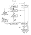
- Fig. 3 is a block diagram showing the construction of the noise suppression apparatus according to the third embodiment of the present invention.
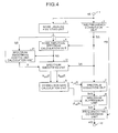
- Fig. 4 is a block diagram showing the construction of the noise suppression apparatus according to the fourth embodiment of the present invention.
- Fig. 5 is a block diagram showing the construction of the noise suppression apparatus according to the sixth embodiment of the present invention.
- Fig. 6 is a block diagram showing the construction of the noise suppression apparatus according to the seventh embodiment of the present invention.
- Fig. 7 shows a graph of noise amplitude correction gain limiting value as a function of all frequency band SNR.
- Fig. 8 shows a graph of noise removal spectrum correction gain limiting value as a function of the input signal power.
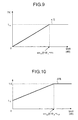
- Fig. 9 shows a graph of the noise amplitude correction gain.
- Fig. 10 shows a graph of the noise removal spectrum correction gain.
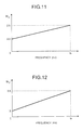
- Fig. 11 shows a graph of the phone reception weighting value W ⁇ as a function of the noise amplitude spectrum correction gain.
- Fig. 12 shows a graph of the phone reception weighting value W ⁇ as a function of the noise removal spectrum correction gain.
- Fig. 13 is a block diagram showing the construction of the noise suppression apparatus of the prior art.
- a noise suppression apparatus according to a first embodiment of the present invention will be explained below, referring to the accompanied figures.
- Fig. 1 is a block diagram showing the construction of the noise suppression apparatus according to the first embodiment of the present invention.
- the apparatus comprises input signal terminal 1, time/frequency conversion unit 2, noise likeness analyzing unit 3, noise amplitude spectrum calculation unit 4, spectrum correction gain limiting value calculation unit 5, correction gain calculation unit 6, spectrum deduction unit 7, spectrum suppression unit 8, frequency/time conversion unit 9 and an output signal terminal 10.
- the spectrum correction gain limiting value calculation unit 5 and the correction gain calculation unit 6 constitute the spectrum correction gain calculation unit.
- An input signal s [t] which is sampled at a predetermined sampling frequency (for example, at 8 kHz) and divided into a set of frames having a predetermined length (for example, 20 ms) is input into the input signal terminal 1.
- the input signal s [t] can be a pure background noise, or it can be a mixture of a voice signal mixed with the background noise.
- the time/frequency conversion unit 2 transforms the input signal s [t] into an amplitude spectrum S [f] and a phase spectrum P [f], using a Fast Fourier Transformation, (for example, 256 points FFT).
- FFT Fast Fourier Transformation
- the noise likeness analyzing unit 3 comprises linear predictive analyzing unit 14, a low pass filter 11, an inverse filter 12, auto-correlation analyzing unit 13 and updating rate coefficient determining unit 15.
- a filtering processing of the input signal is carried out in the low pass filter 11 to obtain a low pass filtered signal.
- the cut-off frequency of this filter is 2 kHz, for example.
- the linear predictive analyzing unit 14 carries out a linear predictive analysis of the low pass filtered signal to obtain a set of linear predictive coefficients, for example, tenth order a parameters.
- the inverse filter 12 carries out an inverse filtering processing of the low pass filtered signal, using the set of linear predictive coefficients, to output a low pass linear predictive residual signal (hereinafter called "low pass residual signal").
- the auto-correlation analyzing unit 13 carries out the auto-correlation analysis of the low pass residual signal, to obtain a positive peak value RAC max .
- the updating rate coefficient determining unit 15 calculates the noise likeness level N level , on the basis of, for example, the positive peak value RAC max , a power Rpow of low pass residual signal of the present frame and a power Fpow in all over the frequency region of the signal of the present frame sent from the input terminal 1. Thereafter the updating rate coefficient determining unit 15 calculates the noise amplitude spectrum updating rate coefficient r, on the basis of the obtained noise likeness level.
- the noise likeness N level is determined, on the basis of the values of a RAC max , Rpow and Fpow, according to the following rule.
- RAC th , R th and F th are, respectively, a threshold value of the maximum of the auto-correlation, a threshold value of the power of the low pass residual signal, and a threshold value of the power in all over the frequency region of the signal of the present frame. Each of them is a predetermined constant value.
- the noise amplitude spectrum updating rate coefficient r is given corresponding to the noise likeness level N level , as shown in Table 1. Larger the value of r is, stronger the influence of the input amplitude spectrum of the present frame on an noise amplitude spectrum N [f] is.
- the noise amplitude spectrum N [f] is an average value of the noise spectrum in the past and is explained below.
- Noise likeness level Noise level Updating rate coefficient r 0 Noise level is high 0.5 1 Noise level is high 0.6 2 Noise level is high 0.8 3 Noise level is high 0.95 4 Noise level is low 0.999
- the noise amplitude spectrum calculation unit 4 updates the noise amplitude spectrum N [f], on the basis of the noise amplitude spectrum updating rate coefficient r, which is sent from the noise likeness analyzing unit 3, and the input amplitude spectrum S [f] output the time/frequency conversion unit 2, according to equation (1).
- N old [f] and N new [f] denote, respectively, the noise amplitude spectrum before and after the updating.
- the noise amplitude spectrum N [f] designates the noise amplitude spectrum N new [f] after the updating.
- N new [f] (1-r) ⁇ N old [f] + r ⁇ S[f]
- the initial value of the noise amplitude spectrum N [f] is given, by setting the noise amplitude spectrum updating rate coefficient r in equation (1) to 1.0.
- the spectrum correction gain limiting value calculation unit 5 calculates a noise amplitude spectrum correction gain limiting value L ⁇ and a noise removing spectrum correction gain limiting value L ⁇ , on the basis of the input amplitude spectrum S [f] sent from the time/frequency conversion unit 2 and the noise amplitude spectrum N [f] sent from the noise amplitude spectrum calculation unit 4.
- the power Pn (dB value) of the noise amplitude spectrum N [f] is obtained, according to equation (3).
- Pn MIN designates a minimum value (dB value) of the power of the noise signal and is a predetermined value.
- the function MAX (a, b) in equation (3) is a function which selects and returns the larger one between its two arguments a and b.
- Pn (dB) MAX(-10 log 10 ( ⁇ (N[f] ⁇ N[f]), Pn MIN )
- the noise amplitude spectrum correction gain limiting value L ⁇ is determined and outputted according to equation (5), on the basis of the all frequency range SNR snr all obtained with equation (4).
- the quantities ⁇ MAX and ⁇ MIN in equation (5) represent, respectively, the maximum value (dB) and the minimum value (dB) of the noise amplitude spectrum correction gains. Each of them is a predetermined constant value.
- the quantities SNR l and SNR h are threshold values regarding the all frequency range SNR. Each of them is a predetermined constant.
- the quantity L ⁇ is a maximum value limiter, which determines the maximum deduction coefficient at the deduction of noise amplitude spectrum from the input amplitude spectrum, which is carried out in the after-mentioned spectrum deduction unit 7.
- Fig. 7 show a profile of L ⁇ in equation (5) with respect to snr all .
- the difference dPs between the input signal power Ps and a threshold value Ps th is calculated according to equation (6).
- Ps th is a threshold value of the input signal power and is a predetermined constant value.
- dPs(dB) Ps - Ps th
- a limiting value L ⁇ of the noise removing spectrum correction gain ⁇ [f] is determined and outputted, according to equation (7).
- the quantity L ⁇ is a maximum value limiter regarding the amplitude suppressing quantity.
- the amplitude suppressing is carried out in the after-mentioned spectrum suppression unit.
- Fig. 8 shows a profile of L ⁇ in equation (7) with respect to Ps.
- the correction gain calculation unit 6 calculates the noise spectrum correction gain ⁇ [f] and the noise removal spectrum correction gain ⁇ [f], on the basis of the input amplitude spectrum S [f], noise amplitude spectrum N [f], noise amplitude spectrum correction gain limiting value L ⁇ and the noise removal spectrum correction gain limiting value L ⁇ .
- ⁇ [f] the noise amplitude spectrum N [f] can be corrected for each frequency component.
- the noise removal spectrum correction gain ⁇ [f] the after-mentioned first noise removal spectrum S s [t] is corrected for each frequency component.
- SNR snr sp [f] which is a proportion of the input amplitude spectrum to the noise amplitude spectrum, is calculated for each frequency component, according to equation (8).
- fn is the Nyquist frequency.
- a noise amplitude spectrum correction gain ⁇ [f] is calculated according to equation (9), on the basis of SNR snr sp [f] for each frequency component obtained with equation (8), the minimum value Pn MIN of the noise power, the noise amplitude spectrum correction gain limiting value L ⁇ and a phone reception weighting value W ⁇ [f].
- the minimum value Pn MIN of the noise power is a predetermined constant value in (9).
- MIN (a, b) is a function, which returns the smaller one between its two arguments a and b.
- gain ⁇ MIN(snr sp [f] ⁇ W ⁇ [f] + Pn, 0)
- ⁇ [f] L ⁇ ⁇ ⁇ (Pn MIN + gain ⁇ )/Pn MIN ⁇
- the value of the phone reception weighting value W ⁇ [f] is predetermined according to its parameter, frequency f. And the value of W ⁇ [f] increases, when the frequency increases. As a result of this weighting, the value of ⁇ [f] decreases in the high frequency region. Consequently an excessive suppression in the high frequency region can be avoided so that a generation of a strange sound in the frequency region can be avoided.
- Fig. 11 shows a profile of the W ⁇ [f].
- the noise removal spectrum correction gain ⁇ [f] is calculated, on the basis of the input amplitude spectrum S [f], the noise amplitude spectrum N [f], a phone reception weighting value W ⁇ [f] and a noise removal correction gain limiting value L ⁇ , according to equation (10).
- the noise removal spectrum correction gain ⁇ [f] is used in the correction of each amplitude of a second noise removal spectrum Sr [f].
- the phone reception weighting value W ⁇ [f] is, similar to the aforementioned W ⁇ [f], predetermined according to its parameter, frequency f.
- the value of W ⁇ [f] increases, when the frequency increases.
- the value of ⁇ [f] decreases in the high frequency region. Consequently, excessive suppression in the high frequency region can be avoided so that a generation of a strange sound in the frequency region can be avoided.
- Fig. 12 shows a profile of the W ⁇ [f].
- the spectrum deduction unit 7 obtains a product of the noise amplitude spectrum N [f] and the noise amplitude spectrum correction gain ⁇ [f], which is sent from the correction gain calculation unit 6. Then, the spectrum deduction unit 7 subtracts the product from the input amplitude spectrum S [f] to output the first noise removal spectrum S s [f], according to equation (11). When the obtained first noise removal spectrum S s [f] is negative, the spectrum deduction unit 7 carries out a recovering procedure, namely the result is changed to zero or a predetermined low level noise n [f]. As a result of the multiplication of the noise spectrum by the correction gain ⁇ [f], it is possible to decrease the reduction by the noise spectrum component, when the SNR is small. And it is possible to increase the reduction by the noise spectrum component, when the SNR is large. Consequently, an excessive spectrum reduction at a small SNR can be suppressed.
- the spectrum suppression unit 8 multiplies the first noise removal spectrum S s [f] by the noise removal spectrum correction gain ⁇ [f], which is sent from the correction gain calculation unit 6, to output a second noise removal spectrum S r [f].
- the noise removal spectrum correction gain ⁇ [f] By multiplying the first noise removal spectrum S s [f] by the noise removal spectrum correction gain ⁇ [f], it is possible to suppress the residual noise after the reduction of the spectrum in the spectrum deduction unit 7. Also a musical noise, which appears as a result of the spectrum deduction, can be suppressed.
- the amplitude suppression at a small SNR is weakened, and the amplitude suppression at a high SNR can be enhanced. As a result, an excessive amplitude suppression at a small SNR can be avoided.
- S r [f] ⁇ [f] ⁇ S s [f]
- the frequency/time conversion unit 9 carries out a procedure inverse to that in the time/frequency conversion unit 2. For example, it carries out an inverse Fast Fourier Transformation to obtain a time signal s r [t], on the basis of the second noise removal spectrum s r [f] and the phase spectrum P [f], then superimposes the time signals at the boundary portions of the neighboring frames to output a noise suppressed signal from the output signal terminal 10.
- the noise amplitude spectrum correction gain ⁇ [f] By multiplying the noise spectrum by the noise amplitude spectrum correction gain ⁇ [f], it is possible to decrease the reduction by the noise spectrum components when SNR is low, and to increase the reduction by the noise spectrum components when the SNR is high. Thus, an excessive spectrum reduction at low SNR can be avoided. Further, by multiplying the first noise removal spectrum by the noise removal spectrum correction gain ⁇ [f], it is possible to suppress the residual noise after the reduction of the spectrum as well as a musical noise, which appears as a result of the spectrum reduction.
- the SNR When the SNR is small, the amplitude suppression is weakened, on the other hand, when the SNR is large, the amplitude suppression can be enforced. Thus, an excessive amplitude suppression at low SNR can be avoided.
- the spectrum reduction procedure and the spectrum amplitude suppression procedure are carried out, corresponding not only to the noise signal level but also to the input signal level. Therefore, an impression of the extinguishment or hiding of the head of words in speech as well as the impression of the spectrum change, which may be caused by an excessive spectrum reduction as well as an excessive suppression, can be avoided. Consequently, it is possible to suppress the noise in noise sections and to avoid an excessive suppression of spectrum in sound sections, simultaneously, thus, a suitable noise suppression can be attained.
- Fig. 2 is a block diagram showing the construction of the noise suppression apparatus according to the second embodiment.
- the construction of the apparatus differs from that shown in Fig. 1 in that the spectrum correction gain limiting value calculation unit 5 is removed, and newly a spectrum smoothing coefficient calculation unit 21 and a spectrum smoothing unit 22 are added.
- the other elements are identical to that in the apparatus of the first embodiment. Therefore, their explanation are omitted.
- the principle of the function of the second embodiment is explained below with reference to Fig.2.
- the spectrum smoothing coefficient calculation unit 21 calculates a time base spectrum smoothing coefficient ⁇ t for smoothing the spectrum in the time base, and a frequency base spectrum smoothing coefficient ⁇ f for smoothing the spectrum in a frequency base, corresponding to the level of the noise likeness of the input signal, which is outputted from the noise likeness determining unit 3.
- the smoothing coefficient corresponding to the noise likeness can be calculated, for example, referring a table which gives a smoothing coefficient corresponding to a noise likeness.
- Table 2 is an example of such a table. Using such a table, it is possible to select smoothing coefficients ⁇ t , ⁇ f so as to enhance the smoothing in noise sections when the noise likeness is large. On the other hand, it is possible to select smoothing coefficients ⁇ t , ⁇ f so as to weaken the smoothing when the noise likeness is small, namely, in sound sections.
- Noise likeness level Noise level Smoothing coefficient ⁇ t Smoothing coefficient ⁇ f 0 Noise level is high 0.5 0.7 1 Noise level is high 0.6 0.8 2 Noise level is high 0.7 0.85 3 Noise level is high 0.8 0.9 4 Noise level is low 0.9 0.95
- the spectrum smoothing unit 22 smoothes the input amplitude spectrum S [f] and the noise amplitude spectrum N [f] in the time base as well as in the frequency base, using the time base smoothing coefficient ⁇ t and the frequency base smoothing coefficient ⁇ f , and calculates a smoothed input amplitude spectrum S sm [f] and a smoothed noise amplitude spectrum N sm [f].
- the input amplitude spectrum S [f] and the noise amplitude spectrum N [f] are smoothed in the time base to calculate a time smoothed input amplitude spectrum S t [f] and a time smoothed noise amplitude spectrum N t [f], according to equation (13).
- the S pre [f], N pre [f] are the input amplitude spectrum and the noise amplitude spectrum in the last former frames.
- fn is the Nyquist frequency.
- the time smoothed input amplitude spectrum S t [f] and the time smoothed noise amplitude spectrum N t [f] are smoothed in the frequency base obtained using equation (13) according to the equation (14) to calculate a smoothed input amplitude spectrum S sm [f] and a smoothed noise amplitude spectrum N sm [f]. They are outputted from the spectrum smoothing unit 22.
- the correction gain calculation unit 6 calculates a noise amplitude spectrum gain ⁇ [f] and a noise removal spectrum correction gain ⁇ [f], in place of the input amplitude spectrum S [f] and the noise amplitude spectrum N [f], using the smoothed input amplitude spectrum S sm [f] and the smoothed noise amplitude spectrum N sm [f].
- the correction gain is obtained, using the smoothed SNR snr sm [f]. Therefore, in noise sections, where the SNR (the ratio of input sound signal to the noise signal) is small, the variation of the spectrum correction gain can be strongly suppressed. On the other hand, in sound sections, where the SNR is large, the variation of the correction gain is not so strongly suppressed.
- the equations (16) and (17) differ from the equations (9) and (10) in the first embodiment.
- the former equations use neither the noise amplitude spectrum correction gain limiting value L ⁇ nor the noise removal spectrum correction gain limiting value L ⁇ .
- the quantity ⁇ max in equation (16) is the noise amplitude spectrum correction gain maximum value
- the spectrum smoothing coefficient is controlled, corresponding to the level of the noise likeness. Therefore, it is possible to select the smoothing coefficients so as to enhance the smoothness, when the noise likeness is strong, to weaken the smoothness, when the noise likeness is small, namely, in sound sections, and to enhance the smoothness, when the noise likeness is strong, namely, in noise section.
- a further suitable control of the spectrum correction gain is possible, and a suitable noise suppression can be attained.
- the feeling that the noise removal spectrum changed discontinuously can be weakened remarkably, when the preciseness of the spectrum correction gain is low, namely when the SNR is low, for example, due to high level noises.
- Fig. 3 is a block diagram showing the construction of the third embodiment.
- the spectrum smoothing unit 22 calculates the limiting values L ⁇ and L ⁇ , on the basis of the smoothed input amplitude spectrum S sm [f] and the smoothed noise amplitude spectrum N sm [f], according to a procedure explained in the second embodiment.
- the spectrum correction gain limiting value calculation unit 5 calculates the noise amplitude spectrum correction gain limiting value L ⁇ and the noise removal spectrum correction gain limiting value L ⁇ , according to a procedure similar to that in the first embodiment.
- the correction gain calculation unit 6 calculates the noise amplitude spectrum correction gain ⁇ [f] and the noise removal spectrum correction gain ⁇ [f], according to equations (9) and (10) as in the first embodiment.
- the smoothed input amplitude spectrum S sm [f] and the smoothed noise amplitude spectrum N sm [f] which are sent from the spectrum smoothing unit 22, along with the noise amplitude spectrum correction gain limiting value L ⁇ and the noise removal spectrum correction gain limiting value L ⁇ , which are sent from the spectrum correction gain limiting value calculation unit 5, are used.
- Fig. 4 is a block diagram showing the construction of the fourth embodiment.
- the spectrum smoothing coefficient calculation unit 21 obtains the SNR SNR fr of the input signal in the present frame, according to equation (18).
- SNR fr ( dB ) 10log 10 ⁇ S [ f ]• S [ f ] ⁇ N [ f ]• N [ f ]
- a temporal coefficient ⁇ t ' of the time base spectrum smoothing coefficient and a temporal coefficient ⁇ f ' of the frequency base spectrum smoothing coefficient are obtained, on the basis of the SNR SNR fr of the frame, according to equation (19).
- the time base spectrum smoothing coefficient is used for smoothing in the time base
- the frequency base spectrum smoothing coefficient is used for smoothing in the frequency base.
- AR smoothing of the temporal smoothing coefficients ⁇ t ' and ⁇ f ' are carried out, using the smoothing coefficients ⁇ (old) t and ⁇ (old) f of the former frame, to output the time base spectrum smoothing coefficient ⁇ t and the frequency base spectrum smoothing coefficient ⁇ f .
- ⁇ t 0.8 ⁇ ⁇ t ' + 0.2 ⁇ ⁇ (old) t
- ⁇ f 0.8 ⁇ ⁇ f ' + 0.2 ⁇ ⁇ (old) f
- the input amplitude spectrum and the noise amplitude spectrum are smoothed, using a spectrum smoothing coefficients, which correspond to the SNR of the input signal.
- a spectrum correction gain is calculated.
- the noise suppression processing is carried out, using the spectrum correction gain. Therefore, the variation of the spectrum correction gain can be controlled, corresponding to the SNR of the input signal.
- the input amplitude spectrum is divided into a plurality of bands, instead of classifying the input amplitude spectrum according to frequency components.
- the noise amplitude spectrum correction gain as well as the noise removal spectrum correction gain are calculated, on the basis of the mean spectrum of each band. And the spectrums can be corrected, using these gains.
- the spectrum band dividing unit precedes the spectrum correction gain limiting value calculation unit 5.
- This spectrum band dividing unit divides the input amplitude spectrum, which is sent from the time/frequency conversion unit 2, into a plurality of frequency bands and calculates the mean spectrum of each of the frequency bands.
- the spectrum band dividing unit divides the noise amplitude spectrum, which is sent from the noise amplitude spectrum calculation unit 4, into a plurality of frequency bands and calculates the average spectrum of each of the frequency bands.
- the spectrum band dividing unit divides the input amplitude spectrum into, for example, 16 channels (hereinafter abbreviated to ch), and calculates the average spectrum S ave [ch] of the input signal of each of the frequency channels and the average spectrum N ave [ch] of the noise signal of each of the frequency channels, according to equation (21).
- n ch is the number of spectrum component in channel ch.
- the spectrum correction gain limiting value calculation unit 5 calculates an input signal power Ps ave and a noise signal power Pn ave , on the basis of the average spectrum S ave [ch] and N ave [ch] obtained using equation (21), and obtains a total SNR snr all-ave , according to equation (22).
- Pn MIN is a minimum noise power and a predetermined constant.
- Ps ave (dB) 10 log 10 ( ⁇ S ave [ch] ⁇ S ave [ch])
- the noise amplitude spectrum correction gain limiting value L ⁇ and the noise removal spectrum correction gain limiting value L ⁇ are calculated, on the basis of the obtained input signal power Ps ave and the noise signal power Pn ave , in place of the Ps and Pn in the first embodiment.
- the correction gain calculation unit 6 calculates the SNR snr sp [ch] of each channel, according equation (23), then calculates the noise amplitude correction gain ⁇ [ch] and the noise removal spectrum correction gain ⁇ [ch] of each channel, on the basis of the SNR snr sp [ch].
- Nch is the total number of the channels.
- the correction gains are inputted to the spectrum deduction unit 7 and the spectrum suppression unit 8. A value corresponding to each of the spectrum component is selected in the unit 7 and 8, respectively. Then the spectrum reduction procedure and the spectrum amplitude suppression procedure are carried out, respectively.
- the input amplitude spectrum can be divided not corresponding to the frequency component but into a plurality of band region, and to calculate the spectrum smoothing coefficient on the basis of the average spectrum of each of the band regions.
- Fig. 5 is a block diagram showing the construction of the sixth embodiment.
- reference numeral 23 denotes a spectrum band dividing unit.
- the spectrum band dividing unit 23 divides the input amplitude spectrum, which is sent from the time/frequency conversion unit 2, into a plurality of frequency bands, and calculates the average spectrum of each of the frequency bands.
- the spectrum band dividing unit 23 divides also the noise amplitude spectrum, which is sent from the noise amplitude spectrum calculation unit 4, into a plurality of frequency bands, and calculates the average spectrum of each of the frequency bands.
- the spectrum band region dividing unit 23 divides the input amplitude spectrum, into 16 bands, for example, and calculates the average spectrum S ave [ch] of the input signal and the average spectrum N ave [ch] of the noise signal in each of the band channel (called channel ch), according to the procedure similar to equation (21).
- the spectrum smoothing coefficient calculation unit 21 calculates the SNR SNR fr-ave of the present frame, on the basis of the average spectrum S ave [ch] of the input signal and the average spectrum N ave [ch] of the noise signal, according to (24).
- SNR fr-ave ( dB ) 10log 10 ⁇ S ave [ ch ]• S ave [ ch ] ⁇ N ave [ ch ]• N ave [ ch ]
- the spectrum smoothing coefficient calculation unit 21 calculates and outputs the time base spectrum smoothing coefficient ⁇ t and the frequency base spectrum smoothing coefficient ⁇ f , on the basis of the SNR SNR fr-ave calculated using the average spectrum, in place of the SNR SNR fr .
- the calculation is carried out, according to equations (14) and (15) in the second embodiment.
- the spectrum smoothing unit 22 smoothes the average spectrum S ave [ch] of the input signal and the average spectrum N ave [ch] of the noise signal in either of the time base and the frequency base, then calculates an average spectrum S sm-ave [ch] of the input signal and a smoothed noise average spectrum N sm-ave [ch], according to equations (25) and (26). This procedure is carried out, on the basis of the time base smoothing coefficient ⁇ t and the frequency base smoothing coefficient ⁇ f , which are obtained from the average spectrum.
- the average spectrum S ave [ch] of the input signal and the average spectrum N ave [ch] of the noise signal are smoothed in the time base, and an average spectrum S t-ave [ch] of the time smoothed input signal and an average spectrum N t-ave [ch] of the time smoothed noise signal are obtained, according to equation (25).
- S pre-ave [ch] and N pre-ave [ch] in equation (25) are, respectively, the average spectrum of the input signal and the average spectrum of the noise signal in the former frame.
- Nch is the maximum number of the channels.
- the average spectrum S t-ave [ch] of the time smoothed input signal and the average spectrum N t-ave [ch] of the time smoothed noise signal obtained according to equation (25) are smoothed in the frequency base, to obtain a smoothed input amplitude spectrum S sm-ave [ch] and a smoothed noise amplitude spectrum N sm-ave [ch], which are outputs of the spectrum smoothing unit, according to equation (26).
- the correction gain calculation unit 6 calculates the noise amplitude spectrum correction gain ⁇ [ch] and the noise removal spectrum correction gain ⁇ [ch] for each of the channels, on the basis of average spectrum S sm-ave [ch] of the smoothed input amplitude spectrum and the average spectrum N sm-ave [ch] of the smoothed noise amplitude spectrum in place of the smoothed input amplitude spectrum S sm [f] and the smoothed noise amplitude spectrum N sm [f].
- a smoothed SNR Snr sm-ave [f] for each of the channels is obtained, on the basis of the average spectrum S sm-ave [ch] of the smoothed input amplitude spectrum and the average spectrum N sm-ave [ch] of the smoothed noise amplitude spectrum, according to equation (27).
- FIG. 6 is a block diagram showing the construction of the seventh embodiment.
- the spectrum band dividing unit 23 divides the input amplitude spectrum into a plurality of frequency bands and calculates the average spectrum for each frequency bands. Further, the spectrum band dividing unit 23 divides the noise amplitude spectrum into a plurality of frequency bands and calculates the average spectrum for each frequency bands, in the same manner as in the sixth embodiment.
- the spectrum smoothing unit 22 smoothes the average spectrum S ave [ch] for each frequency band of the input signal and the average spectrum N ave [ch] for each frequency band of the noise signal.
- the smoothing is carried out in the time base and in the frequency base, using the time smoothing coefficient ⁇ t and the frequency smoothing coefficient ⁇ f , which are obtained in the spectrum smoothing coefficient calculation unit 21 so that a smoothed input average spectrum S sm-ave [ch] and a smoothed noise average spectrum N sm-ave [ch] are calculated.
- the spectrum correction gain limiting value calculation unit 5 calculates the input signal power Ps ave and the noise signal power Pn ave , on the basis of the smoothed input average spectrum S sm-ave [ch] and the smoothed noise average spectrum N sm-ave [ch], according to equation (22) so as to calculate an all frequency range SNR snr all-ave .
- Pn MIN in equation (22) is a minimum noise power and is a predetermined constant.
- the noise amplitude spectrum correction gain limiting value L ⁇ and the noise removal spectrum correction gain limiting value L ⁇ are calculated, on the basis of the obtained input signal power Ps ave and the noise signal power Pn ave in place of the Ps and Pn in the first embodiment.
- the correction gain calculation unit 6 obtains the SNR snr sp [ch] for each channel, according to equation (23), then calculates the noise amplitude spectrum correction gain ⁇ [ch] and noise removal spectrum correction gain ⁇ [ch], using the obtained SNR Snr sp [ch].
- N ch in equation (23) is the total number of the channels.
- the noise suppression apparatus As explained above, in the noise suppression apparatus according to one aspect of the present invention, following procedures is carried out. That is, corresponding to the noise likeness of the input signal frame, the noise amplitude spectrum is calculated using the input amplitude spectrum of the frame, then the noise amplitude spectrum correction gain and the noise removal spectrum correction gain are calculated on the basis of the noise amplitude spectrum, an input amplitude spectrum and respective coefficients; the first noise removal spectrum is calculated by deducting the product of the noise amplitude spectrum and the noise amplitude spectrum correction gain from the input amplitude spectrum; the second noise removal spectrum is calculated by multiplying the first noise removal spectrum by the noise removal spectrum correction gain, which is sent from the correction gain calculation unit; and the second noise removal spectrum is transformed into a time domain signal.
- the noise removal spectrum correction gain is multiplied by the first noise removal spectrum, so-called residual noises, which may be caused by the residual noise, which is the residual portion of the spectrum after the spectrum reduction and so-called musical noises, which may be caused by the spectrum reduction, can be suppressed.
- a spectrum smoothing coefficient control corresponding to the noise likeness is attained, by carrying out the following procedures. That is, smoothing of the input amplitude spectrum and the noise amplitude spectrum in the time base and the frequency base, on the basis of the input amplitude spectrum and the noise amplitude spectrum, corresponding to the state of the input signal; the calculation of the smoothed input amplitude spectrum and the smoothed noise amplitude spectrum; and the calculation of the noise amplitude spectrum correction gain and the noise removal spectrum correction gain, on the basis of the smoothed input amplitude spectrum and the smoothed noise amplitude spectrum.
- the spectrum smoothing coefficient is controlled, corresponding to the level of the noise likeness.
- the noise suppression apparatus further comprises a spectrum band dividing unit for dividing the input amplitude spectrum into a plurality of the frequency bands to output an average spectrum for each of the frequency bands, and for dividing the noise amplitude spectrum into a plurality of the frequency bands to output an average spectrum for each of the frequency bands, the average spectra are used in calculations of the smoothing coefficients and the smoothed spectrums.
- the input amplitude spectrum and the noise amplitude spectrum are smoothed, on the basis of the spectrum smoothing coefficients corresponding to the state of the input signal, and the noise suppression processing is carried out, on the basis of the spectrum correction gain, which is calculated from the smoothed input amplitude spectrum and the noise amplitude spectrum.
- the variation of the spectrum correction gain can be controlled, corresponding to the state of the input signal. For example, even when the SNR is low, i.e., in noise sections, etc, the impression of the discontinuity in the noise removal spectrum in the time base and the frequency base can be reduced, and the generation of strange sound in such sections can be avoided, namely a stable noise suppression can be attained.
- the following procedure is carried out. That is, smoothing of the input amplitude spectrum and the noise amplitude spectrum, on the basis of the smoothing coefficients of the input amplitude spectrum and the noise amplitude spectrum, corresponding to the state of the input signal; calculations of the smoothed input amplitude spectrum and the smoothed noise amplitude spectrum; and calculations of the noise amplitude spectrum correction gain and the noise removal spectrum correction gain, on the basis of the smoothed input amplitude spectrum, smoothed noise amplitude spectrum and the spectrum correction gain limiting value.
- the input amplitude spectrum is divided into a plurality of frequency bands and the average spectrum is calculated;
- the noise amplitude spectrum is divided into a plurality of frequency bands and the average spectrum is calculated;
- the smoothing coefficients of the input amplitude spectrum and the noise amplitude spectrum are calculated for each frequency band;
- the smoothed input amplitude spectrum and the smoothed noise amplitude spectrum are calculated, on the basis of the input amplitude average spectrum of each frequency band and the noise amplitude average spectrum of each frequency band.
- the spectrum smoothing coefficient is controlled, corresponding to the level of the noise likeness.
- the spectrum smoothing coefficient calculation unit, the spectrum smoothing unit, the spectrum correction gain limiting value calculation unit and the correction gain calculation unit do not use the input amplitude spectrum nor the noise amplitude spectrum, but use average spectra which are obtained, respectively, by dividing the input amplitude spectrum and the noise amplitude spectrum into a plurality of frequency bands and by calculating their average spectra.
- the spectrum smoothing coefficient is controlled, corresponding to the level of the noise likeness.
Landscapes
- Engineering & Computer Science (AREA)
- Computational Linguistics (AREA)
- Quality & Reliability (AREA)
- Signal Processing (AREA)
- Health & Medical Sciences (AREA)
- Audiology, Speech & Language Pathology (AREA)
- Human Computer Interaction (AREA)
- Physics & Mathematics (AREA)
- Acoustics & Sound (AREA)
- Multimedia (AREA)
- Noise Elimination (AREA)
- Compression, Expansion, Code Conversion, And Decoders (AREA)
Abstract
Description
start:
Nlevel = 0 ;;; the noise likeness level is cleared to zero
if (RACmax > RACth) Nlevel = Nlevel + 2
if (Rpow > Rpowth) Nlevel = Nlevel + 1
if (Fpow > Fpowth) Nlevel = Nlevel + 1
output Nlevel ;;; the noise likeness level is outputted
end:
| Noise likeness level | Noise level | Updating rate coefficient r |
| 0 | Noise level is high | 0.5 |
| 1 | Noise level is high | 0.6 |
| 2 | Noise level is high | 0.8 |
| 3 | Noise level is high | 0.95 |
| 4 | Noise level is low | 0.999 |




| Noise likeness level | Noise level | Smoothing coefficient γt | Smoothing coefficient γf |
| 0 | Noise level is high | 0.5 | 0.7 |
| 1 | Noise level is high | 0.6 | 0.8 |
| 2 | Noise level is high | 0.7 | 0.85 |
| 3 | Noise level is high | 0.8 | 0.9 |
| 4 | Noise level is low | 0.9 | 0.95 |





Claims (8)
- A noise suppression apparatus, which can remove an inutile noise from an input signal comprising an object signal and the inutile noise mixed therein to output the object signal, said apparatus comprising:a time/frequency conversion unit (2) which converts the input signal into an amplitude spectrum and a phase spectrum by frequency-analyzing the input signal in each frame;a noise-likeness analyzing unit (3) which determines the noise-likeness of the input signal frame;a noise amplitude spectrum calculation unit (4) which calculates the noise amplitude spectrum from the input amplitude spectrum of the frame on the basis of the result of said noise-likeness analyzing unit (3);a spectrum correction gain calculation unit which calculates a noise amplitude spectrum correction gain, on the basis of the input amplitude spectrum, the noise amplitude spectrum and a first predetermined coefficient, and which calculates a noise removal spectrum correction gain, on the basis of the input amplitude spectrum, the noise amplitude spectrum and a second predetermined coefficient;a spectrum deduction unit (7) which calculates a product of the noise amplitude spectrum and the noise amplitude spectrum correction gain, which is sent from said spectrum correction gain calculation unit, then deducts the product from the input amplitude spectrum so as to output a first noise removal spectrum;a spectrum suppression unit (8) which calculates a product of the first noise removal spectrum and the noise removal spectrum correction gain so as to output a second noise removal spectrum; anda frequency/time conversion unit (9) which converting the second noise removal spectrum to a time domain signal.
- The noise suppression apparatus according to claim 1 wherein said spectrum correction gain calculation unit comprises,a spectrum correction gain limiting value calculation unit (5) which calculates spectrum correction gain limiting values, on the basis of the input amplitude spectrum and the noise amplitude spectrum, which spectrum correction gain limiting values limit the correction gains of the noise amplitude spectrum and the noise removal spectrum; anda correction gain calculation unit (6) which calculates a noise amplitude spectrum correction gain and a noise removal spectrum correction gain, on the basis of the input amplitude spectrum, the noise amplitude spectrum and the spectrum correction gain limiting value, which noise amplitude spectrum correction gain corrects the value of the amplitude of the noise amplitude spectrum in each frequency component, and which noise removal spectrum correction gain corrects the value of the amplitude of the noise removal spectrum for each frequency component.
- The noise suppression apparatus according to claim 2 further comprising a spectrum band dividing unit (23) which divides the input amplitude spectrum sent from said time/frequency conversion unit (2) into a plurality of frequency bands and calculates the average spectrum of each frequency band, and divides the noise amplitude spectrum from said noise amplitude spectrum calculation unit (4) into a plurality of frequency bands and calculates the average spectrum of each frequency band,
wherein said spectrum correction gain limiting value calculation unit (5) and said correction gain calculation unit (6), that form said spectrum correction gain calculation unit, calculate the spectrum amplitude limiting value, noise amplitude spectrum correction gain and the noise removal spectrum correction gain, on the basis of average spectrum of each frequency band of the input amplitude spectrum and the noise amplitude spectrum, which are outputs of said spectrum band dividing unit (23), in place of the input amplitude spectrum and the noise amplitude spectrum. - The noise suppression apparatus according to claim 1 further comprising,wherein said spectrum correction gain calculation unit comprises a correction gain calculation unit (6) which calculates a noise amplitude spectrum correction gain and a noise removal spectrum correction gain, on the basis of the smoothed input amplitude spectrum and the smoothed noise amplitude spectrum, which noise amplitude spectrum correction gain is used for correcting the value of the amplitude for each frequency component of the noise amplitude spectrum, and which noise removal spectrum correction gain is used for correcting the value of the amplitude of the noise removal spectrum.a spectrum smoothing coefficient calculation unit (21) which calculates smoothing coefficients of the input amplitude spectrum and the noise amplitude spectrum, according to the state of the input signal; anda spectrum smoothing unit (22) which smoothes the input amplitude spectrum and the noise amplitude spectrum in the time base and in the frequency base, on the basis of the spectrum smoothing coefficients, and outputs a smoothed input amplitude spectrum and a smoothed noise amplitude spectrum,
- The noise suppression apparatus according to claim 4 further comprising a spectrum band dividing unit (23) which divides the input amplitude spectrum sent from said time/frequency conversion unit (2) into a plurality of frequency bands and calculates the average spectrum of each frequency band, and divides the noise amplitude spectrum sent from said noise amplitude spectrum calculation unit and calculates the average spectrum of each frequency band,wherein said spectrum smoothing coefficient calculation unit (21) calculates smoothing coefficients for the input amplitude spectrum and the noise amplitude spectrum, on the basis of the input amplitude average spectrum of each frequency band and the noise amplitude average spectrum of each frequency band, which are sent from said spectrum band dividing unit (23), andwherein said spectrum smoothing unit (22) calculates the smoothed input amplitude spectrum and the smoothed noise amplitude spectrum, on the basis of the input amplitude average spectrum of each frequency band and the noise amplitude average spectrum of each frequency band, which are sent from said spectrum band dividing unit (23).
- The noise suppression apparatus according to claim 2 further comprising,wherein said correction gain calculation unit (6) calculates the noise amplitude spectrum correction gain and the noise removal spectrum correction gain, on the basis of the smoothed input amplitude spectrum, smoothed noise amplitude spectrum and the spectrum correction gain limiting value, in place of the input amplitude spectrum and the noise amplitude spectrum.a spectrum smoothing coefficient calculation unit (21) which calculates the smoothing coefficients for the input amplitude spectrum and the noise amplitude spectrum, according to the state of the input signal; anda spectrum smoothing unit (22) which smoothes the input amplitude spectrum and the noise amplitude spectrum in the time base and in the frequency base, using the smoothing coefficients of the spectra,
- The noise suppression apparatus according to claim 6 further comprising a spectrum band dividing unit (23) which divides the input amplitude spectrum sent from said time/frequency conversion unit (2) into a plurality of frequency bands and calculates the average spectrum of each frequency band, and divides the noise amplitude spectrum sent from said noise amplitude spectrum calculation unit (4) into a plurality of frequency bands and calculates the average spectrum of each frequency band,
wherein said spectrum smoothing coefficient calculation unit (21), said spectrum smoothing unit (22), said spectrum correction gain limiting value calculation unit (5) and said correction gain calculation unit (6) use the output from said spectrum band dividing unit (23) in place of the input amplitude spectrum and the noise amplitude spectrum, for carrying out their function. - The noise suppression apparatus according to any one of claims 4 to 7 wherein said spectrum smoothing coefficient calculation unit (21) calculates the smoothing coefficients for the input amplitude spectrum and the noise amplitude spectrum, according to the result of the noise likeness analyzing unit (3).
Applications Claiming Priority (2)
| Application Number | Priority Date | Filing Date | Title |
|---|---|---|---|
| JP31912699 | 1999-11-10 | ||
| JP31912699A JP3454206B2 (en) | 1999-11-10 | 1999-11-10 | Noise suppression device and noise suppression method |
Publications (3)
| Publication Number | Publication Date |
|---|---|
| EP1100077A2 true EP1100077A2 (en) | 2001-05-16 |
| EP1100077A3 EP1100077A3 (en) | 2002-07-10 |
| EP1100077B1 EP1100077B1 (en) | 2008-11-26 |
Family
ID=18106764
Family Applications (1)
| Application Number | Title | Priority Date | Filing Date |
|---|---|---|---|
| EP00115227A Expired - Lifetime EP1100077B1 (en) | 1999-11-10 | 2000-07-13 | Noise suppression apparatus |
Country Status (5)
| Country | Link |
|---|---|
| US (1) | US7158932B1 (en) |
| EP (1) | EP1100077B1 (en) |
| JP (1) | JP3454206B2 (en) |
| CN (1) | CN1192360C (en) |
| DE (1) | DE60040895D1 (en) |
Cited By (5)
| Publication number | Priority date | Publication date | Assignee | Title |
|---|---|---|---|---|
| WO2002101729A1 (en) * | 2001-06-06 | 2002-12-19 | Mitsubishi Denki Kabushiki Kaisha | Noise suppressor |
| WO2003041054A3 (en) * | 2001-11-08 | 2003-09-04 | Global Ip Sound Ab | Enhancement of a coded speech signal |
| US7957964B2 (en) | 2004-12-28 | 2011-06-07 | Pioneer Corporation | Apparatus and methods for noise suppression in sound signals |
| RU2573274C1 (en) * | 2014-11-05 | 2016-01-20 | Общество с ограниченной ответственностью Научно-производственное предприятие "ЭКРА" | Method of removing pulse noise (emission) from electrical quantity |
| EP3276621A1 (en) * | 2016-07-27 | 2018-01-31 | Fujitsu Limited | Noise suppression device and noise suppressing method |
Families Citing this family (65)
| Publication number | Priority date | Publication date | Assignee | Title |
|---|---|---|---|---|
| FI19992453L (en) | 1999-11-15 | 2001-05-16 | Nokia Mobile Phones Ltd | Noise reduction |
| JP4282227B2 (en) | 2000-12-28 | 2009-06-17 | 日本電気株式会社 | Noise removal method and apparatus |
| RU2204203C1 (en) * | 2002-05-30 | 2003-05-10 | Федеральное Государственное унитарное предприятие Воронежский научно-исследовательский институт связи | Narrow-band noise suppression device |
| US8073689B2 (en) * | 2003-02-21 | 2011-12-06 | Qnx Software Systems Co. | Repetitive transient noise removal |
| US7725315B2 (en) * | 2003-02-21 | 2010-05-25 | Qnx Software Systems (Wavemakers), Inc. | Minimization of transient noises in a voice signal |
| US7885420B2 (en) * | 2003-02-21 | 2011-02-08 | Qnx Software Systems Co. | Wind noise suppression system |
| US8326621B2 (en) | 2003-02-21 | 2012-12-04 | Qnx Software Systems Limited | Repetitive transient noise removal |
| US7949522B2 (en) | 2003-02-21 | 2011-05-24 | Qnx Software Systems Co. | System for suppressing rain noise |
| US7895036B2 (en) * | 2003-02-21 | 2011-02-22 | Qnx Software Systems Co. | System for suppressing wind noise |
| US8271279B2 (en) | 2003-02-21 | 2012-09-18 | Qnx Software Systems Limited | Signature noise removal |
| JP2004341339A (en) * | 2003-05-16 | 2004-12-02 | Mitsubishi Electric Corp | Noise suppression device |
| JP4608650B2 (en) * | 2003-05-30 | 2011-01-12 | 独立行政法人産業技術総合研究所 | Known acoustic signal removal method and apparatus |
| JP4520732B2 (en) * | 2003-12-03 | 2010-08-11 | 富士通株式会社 | Noise reduction apparatus and reduction method |
| EP2929782A1 (en) * | 2004-01-23 | 2015-10-14 | Ocata Therapeutics, Inc. | Improved modalities for the treatment of degenerative diseases of the retina |
| US7725314B2 (en) * | 2004-02-16 | 2010-05-25 | Microsoft Corporation | Method and apparatus for constructing a speech filter using estimates of clean speech and noise |
| JP4542399B2 (en) * | 2004-09-15 | 2010-09-15 | 日本放送協会 | Speech spectrum estimation apparatus and speech spectrum estimation program |
| EP1806739B1 (en) * | 2004-10-28 | 2012-08-15 | Fujitsu Ltd. | Noise suppressor |
| KR100657948B1 (en) * | 2005-02-03 | 2006-12-14 | 삼성전자주식회사 | Voice Enhancement Device and Method |
| US7596231B2 (en) * | 2005-05-23 | 2009-09-29 | Hewlett-Packard Development Company, L.P. | Reducing noise in an audio signal |
| JP4670483B2 (en) * | 2005-05-31 | 2011-04-13 | 日本電気株式会社 | Method and apparatus for noise suppression |
| WO2006130909A1 (en) * | 2005-06-10 | 2006-12-14 | Neuromonics Pty Ltd | Digital playback device and method and apparatus for spectrally modifying a digital audio signal |
| JP4520970B2 (en) * | 2005-11-21 | 2010-08-11 | 日本電信電話株式会社 | Similarity calculation device, echo cancellation device, similarity calculation method, echo cancellation method |
| JP4863713B2 (en) * | 2005-12-29 | 2012-01-25 | 富士通株式会社 | Noise suppression device, noise suppression method, and computer program |
| JP2007199017A (en) * | 2006-01-30 | 2007-08-09 | Omron Corp | Allophone clarification method, allophone clarification device, and allophone inspection device |
| JP4965891B2 (en) * | 2006-04-25 | 2012-07-04 | キヤノン株式会社 | Signal processing apparatus and method |
| JP4836720B2 (en) | 2006-09-07 | 2011-12-14 | 株式会社東芝 | Noise suppressor |
| JP4753821B2 (en) | 2006-09-25 | 2011-08-24 | 富士通株式会社 | Sound signal correction method, sound signal correction apparatus, and computer program |
| CN100483509C (en) * | 2006-12-05 | 2009-04-29 | 华为技术有限公司 | Aural signal classification method and device |
| JP2008148179A (en) * | 2006-12-13 | 2008-06-26 | Fujitsu Ltd | Noise suppression processing method in audio signal processing apparatus and automatic gain control apparatus |
| WO2008108721A1 (en) | 2007-03-05 | 2008-09-12 | Telefonaktiebolaget Lm Ericsson (Publ) | Method and arrangement for controlling smoothing of stationary background noise |
| JP5156260B2 (en) * | 2007-04-27 | 2013-03-06 | ニュアンス コミュニケーションズ,インコーポレイテッド | Method for removing target noise and extracting target sound, preprocessing unit, speech recognition system and program |
| JP2008309955A (en) * | 2007-06-13 | 2008-12-25 | Toshiba Corp | Noise suppressor |
| US8538763B2 (en) * | 2007-09-12 | 2013-09-17 | Dolby Laboratories Licensing Corporation | Speech enhancement with noise level estimation adjustment |
| JP5012995B2 (en) * | 2008-03-24 | 2012-08-29 | 株式会社Jvcケンウッド | Audio signal processing apparatus and audio signal processing method |
| US9159335B2 (en) * | 2008-10-10 | 2015-10-13 | Samsung Electronics Co., Ltd. | Apparatus and method for noise estimation, and noise reduction apparatus employing the same |
| JP5245714B2 (en) * | 2008-10-24 | 2013-07-24 | ヤマハ株式会社 | Noise suppression device and noise suppression method |
| JP5131149B2 (en) * | 2008-10-24 | 2013-01-30 | ヤマハ株式会社 | Noise suppression device and noise suppression method |
| WO2010046954A1 (en) * | 2008-10-24 | 2010-04-29 | 三菱電機株式会社 | Noise suppression device and audio decoding device |
| JP5252563B2 (en) * | 2009-01-20 | 2013-07-31 | Necシステムテクノロジー株式会社 | Electronic device, diagnosis method of mechanical component in electronic device, and diagnostic program |
| CN101986386B (en) * | 2009-07-29 | 2012-09-26 | 比亚迪股份有限公司 | Method and device for eliminating voice background noise |
| JP5754899B2 (en) | 2009-10-07 | 2015-07-29 | ソニー株式会社 | Decoding apparatus and method, and program |
| US8666092B2 (en) * | 2010-03-30 | 2014-03-04 | Cambridge Silicon Radio Limited | Noise estimation |
| JP5850216B2 (en) | 2010-04-13 | 2016-02-03 | ソニー株式会社 | Signal processing apparatus and method, encoding apparatus and method, decoding apparatus and method, and program |
| EP2579254B1 (en) * | 2010-05-24 | 2017-07-12 | Nec Corporation | Signal processing method, information processing device, and signal processing program |
| CN102270454A (en) * | 2010-06-07 | 2011-12-07 | 宇达电脑(上海)有限公司 | method and device for improving audio output |
| JP6075743B2 (en) | 2010-08-03 | 2017-02-08 | ソニー株式会社 | Signal processing apparatus and method, and program |
| JP2012058358A (en) * | 2010-09-07 | 2012-03-22 | Sony Corp | Noise suppression apparatus, noise suppression method and program |
| JP5707842B2 (en) | 2010-10-15 | 2015-04-30 | ソニー株式会社 | Encoding apparatus and method, decoding apparatus and method, and program |
| CN103718241B (en) * | 2011-11-02 | 2016-05-04 | 三菱电机株式会社 | Noise-suppressing device |
| JP2013148724A (en) * | 2012-01-19 | 2013-08-01 | Sony Corp | Noise suppressing device, noise suppressing method, and program |
| US20150287406A1 (en) * | 2012-03-23 | 2015-10-08 | Google Inc. | Estimating Speech in the Presence of Noise |
| WO2013140733A1 (en) | 2012-03-23 | 2013-09-26 | パナソニック株式会社 | Band power computation device and band power computation method |
| JP2014123011A (en) * | 2012-12-21 | 2014-07-03 | Sony Corp | Noise detector, method, and program |
| JP6439682B2 (en) | 2013-04-11 | 2018-12-19 | 日本電気株式会社 | Signal processing apparatus, signal processing method, and signal processing program |
| JP6263890B2 (en) * | 2013-07-25 | 2018-01-24 | 沖電気工業株式会社 | Audio signal processing apparatus and program |
| JP6531649B2 (en) | 2013-09-19 | 2019-06-19 | ソニー株式会社 | Encoding apparatus and method, decoding apparatus and method, and program |
| KR102356012B1 (en) | 2013-12-27 | 2022-01-27 | 소니그룹주식회사 | Decoding device, method, and program |
| US10410645B2 (en) * | 2014-03-03 | 2019-09-10 | Samsung Electronics Co., Ltd. | Method and apparatus for high frequency decoding for bandwidth extension |
| KR102653849B1 (en) | 2014-03-24 | 2024-04-02 | 삼성전자주식회사 | Method and apparatus for encoding highband and method and apparatus for decoding high band |
| JP6379839B2 (en) * | 2014-08-11 | 2018-08-29 | 沖電気工業株式会社 | Noise suppression device, method and program |
| JP6447357B2 (en) * | 2015-05-18 | 2019-01-09 | 株式会社Jvcケンウッド | Audio signal processing apparatus, audio signal processing method, and audio signal processing program |
| CN105445549B (en) * | 2015-12-11 | 2019-09-06 | 中国电子科技集团公司第四十一研究所 | A Spectrum Measurement Method for Weak Electromagnetic Signals |
| JP6707914B2 (en) * | 2016-03-08 | 2020-06-10 | 沖電気工業株式会社 | Gain processing device and program, and acoustic signal processing device and program |
| CN111147983A (en) * | 2018-11-06 | 2020-05-12 | 展讯通信(上海)有限公司 | Speaker control method and device, and readable storage medium |
| CN111144347B (en) * | 2019-12-30 | 2023-06-27 | 腾讯科技(深圳)有限公司 | Data processing method, device, platform and storage medium |
Family Cites Families (11)
| Publication number | Priority date | Publication date | Assignee | Title |
|---|---|---|---|---|
| US4811404A (en) * | 1987-10-01 | 1989-03-07 | Motorola, Inc. | Noise suppression system |
| ES2137355T3 (en) | 1993-02-12 | 1999-12-16 | British Telecomm | NOISE REDUCTION. |
| JPH07193548A (en) * | 1993-12-25 | 1995-07-28 | Sony Corp | Noise reduction processing method |
| JP3484757B2 (en) | 1994-05-13 | 2004-01-06 | ソニー株式会社 | Noise reduction method and noise section detection method for voice signal |
| JP3484801B2 (en) | 1995-02-17 | 2004-01-06 | ソニー株式会社 | Method and apparatus for reducing noise of audio signal |
| JP3591068B2 (en) * | 1995-06-30 | 2004-11-17 | ソニー株式会社 | Noise reduction method for audio signal |
| JPH09212196A (en) | 1996-01-31 | 1997-08-15 | Nippon Telegr & Teleph Corp <Ntt> | Noise suppression device |
| FR2768547B1 (en) | 1997-09-18 | 1999-11-19 | Matra Communication | METHOD FOR NOISE REDUCTION OF A DIGITAL SPEAKING SIGNAL |
| JPH11162240A (en) | 1997-11-28 | 1999-06-18 | Matsushita Electric Works Ltd | lighting equipment |
| JP3454190B2 (en) * | 1999-06-09 | 2003-10-06 | 三菱電機株式会社 | Noise suppression apparatus and method |
| US6671667B1 (en) * | 2000-03-28 | 2003-12-30 | Tellabs Operations, Inc. | Speech presence measurement detection techniques |
-
1999
- 1999-11-10 JP JP31912699A patent/JP3454206B2/en not_active Expired - Lifetime
-
2000
- 2000-06-21 US US09/599,367 patent/US7158932B1/en not_active Expired - Fee Related
- 2000-07-13 DE DE60040895T patent/DE60040895D1/en not_active Expired - Lifetime
- 2000-07-13 EP EP00115227A patent/EP1100077B1/en not_active Expired - Lifetime
- 2000-07-31 CN CNB001221361A patent/CN1192360C/en not_active Expired - Fee Related
Cited By (8)
| Publication number | Priority date | Publication date | Assignee | Title |
|---|---|---|---|---|
| WO2002101729A1 (en) * | 2001-06-06 | 2002-12-19 | Mitsubishi Denki Kabushiki Kaisha | Noise suppressor |
| CN1308914C (en) * | 2001-06-06 | 2007-04-04 | 三菱电机株式会社 | Noise suppressor |
| US7302065B2 (en) | 2001-06-06 | 2007-11-27 | Mitsubishi Denki Kabushiki Kaisha | Noise suppressor |
| WO2003041054A3 (en) * | 2001-11-08 | 2003-09-04 | Global Ip Sound Ab | Enhancement of a coded speech signal |
| US7957964B2 (en) | 2004-12-28 | 2011-06-07 | Pioneer Corporation | Apparatus and methods for noise suppression in sound signals |
| RU2573274C1 (en) * | 2014-11-05 | 2016-01-20 | Общество с ограниченной ответственностью Научно-производственное предприятие "ЭКРА" | Method of removing pulse noise (emission) from electrical quantity |
| EP3276621A1 (en) * | 2016-07-27 | 2018-01-31 | Fujitsu Limited | Noise suppression device and noise suppressing method |
| US10679641B2 (en) | 2016-07-27 | 2020-06-09 | Fujitsu Limited | Noise suppression device and noise suppressing method |
Also Published As
| Publication number | Publication date |
|---|---|
| EP1100077B1 (en) | 2008-11-26 |
| DE60040895D1 (en) | 2009-01-08 |
| JP2001134287A (en) | 2001-05-18 |
| US7158932B1 (en) | 2007-01-02 |
| JP3454206B2 (en) | 2003-10-06 |
| CN1296258A (en) | 2001-05-23 |
| EP1100077A3 (en) | 2002-07-10 |
| CN1192360C (en) | 2005-03-09 |
| HK1037052A1 (en) | 2002-01-25 |
Similar Documents
| Publication | Publication Date | Title |
|---|---|---|
| US7158932B1 (en) | Noise suppression apparatus | |
| RU2127454C1 (en) | Method for noise suppression | |
| JP3574123B2 (en) | Noise suppression device | |
| RU2121719C1 (en) | Method and device for noise reduction in voice signal | |
| JP4162604B2 (en) | Noise suppression device and noise suppression method | |
| JP4219898B2 (en) | Speech enhancement device | |
| JP3457293B2 (en) | Noise suppression device and noise suppression method | |
| US5479560A (en) | Formant detecting device and speech processing apparatus | |
| US9854368B2 (en) | Method of operating a hearing aid system and a hearing aid system | |
| KR20010052750A (en) | A noise suppressor having weighted gain smoothing | |
| US20100150376A1 (en) | Echo suppressing apparatus, echo suppressing system, echo suppressing method and recording medium | |
| JP3858668B2 (en) | Noise removal method and apparatus | |
| JP3454403B2 (en) | Band division type noise reduction method and apparatus | |
| JPH06208395A (en) | Formant detecting device and sound processing device | |
| EP1278185A2 (en) | Method for improving noise reduction in speech transmission | |
| JP4227421B2 (en) | Speech enhancement device and portable terminal | |
| EP3531719B1 (en) | Dereverberation device and hearing aid | |
| EP1211671A2 (en) | Automatic gain control with noise suppression | |
| KR100746680B1 (en) | Voice highlighting device | |
| JP6677110B2 (en) | Audio signal processing device and audio signal processing program | |
| JP2001267973A (en) | Noise suppression device and noise suppression method | |
| JP2022011892A (en) | Noise suppression circuit |
Legal Events
| Date | Code | Title | Description |
|---|---|---|---|
| PUAI | Public reference made under article 153(3) epc to a published international application that has entered the european phase |
Free format text: ORIGINAL CODE: 0009012 |
|
| AK | Designated contracting states |
Kind code of ref document: A2 Designated state(s): AT BE CH CY DE DK ES FI FR GB GR IE IT LI LU MC NL PT SE |
|
| AX | Request for extension of the european patent |
Free format text: AL;LT;LV;MK;RO;SI |
|
| PUAL | Search report despatched |
Free format text: ORIGINAL CODE: 0009013 |
|
| AK | Designated contracting states |
Kind code of ref document: A3 Designated state(s): AT BE CH CY DE DK ES FI FR GB GR IE IT LI LU MC NL PT SE |
|
| AX | Request for extension of the european patent |
Free format text: AL;LT;LV;MK;RO;SI |
|
| 17P | Request for examination filed |
Effective date: 20020719 |
|
| AKX | Designation fees paid |
Designated state(s): DE FR GB |
|
| 17Q | First examination report despatched |
Effective date: 20040302 |
|
| RAP1 | Party data changed (applicant data changed or rights of an application transferred) |
Owner name: MITSUBISHI DENKI KABUSHIKI KAISHA |
|
| 17Q | First examination report despatched |
Effective date: 20040302 |
|
| GRAP | Despatch of communication of intention to grant a patent |
Free format text: ORIGINAL CODE: EPIDOSNIGR1 |
|
| GRAS | Grant fee paid |
Free format text: ORIGINAL CODE: EPIDOSNIGR3 |
|
| GRAA | (expected) grant |
Free format text: ORIGINAL CODE: 0009210 |
|
| AK | Designated contracting states |
Kind code of ref document: B1 Designated state(s): DE FR GB |
|
| REG | Reference to a national code |
Ref country code: GB Ref legal event code: FG4D |
|
| REF | Corresponds to: |
Ref document number: 60040895 Country of ref document: DE Date of ref document: 20090108 Kind code of ref document: P |
|
| PLBE | No opposition filed within time limit |
Free format text: ORIGINAL CODE: 0009261 |
|
| STAA | Information on the status of an ep patent application or granted ep patent |
Free format text: STATUS: NO OPPOSITION FILED WITHIN TIME LIMIT |
|
| 26N | No opposition filed |
Effective date: 20090827 |
|
| REG | Reference to a national code |
Ref country code: GB Ref legal event code: 746 Effective date: 20110513 |
|
| REG | Reference to a national code |
Ref country code: DE Ref legal event code: R084 Ref document number: 60040895 Country of ref document: DE Effective date: 20110706 Ref country code: DE Ref legal event code: R084 Ref document number: 60040895 Country of ref document: DE Effective date: 20110506 |
|
| PGFP | Annual fee paid to national office [announced via postgrant information from national office to epo] |
Ref country code: GB Payment date: 20140709 Year of fee payment: 15 Ref country code: FR Payment date: 20140708 Year of fee payment: 15 |
|
| PGFP | Annual fee paid to national office [announced via postgrant information from national office to epo] |
Ref country code: DE Payment date: 20150707 Year of fee payment: 16 |
|
| GBPC | Gb: european patent ceased through non-payment of renewal fee |
Effective date: 20150713 |
|
| PG25 | Lapsed in a contracting state [announced via postgrant information from national office to epo] |
Ref country code: GB Free format text: LAPSE BECAUSE OF NON-PAYMENT OF DUE FEES Effective date: 20150713 |
|
| REG | Reference to a national code |
Ref country code: FR Ref legal event code: ST Effective date: 20160331 |
|
| PG25 | Lapsed in a contracting state [announced via postgrant information from national office to epo] |
Ref country code: FR Free format text: LAPSE BECAUSE OF NON-PAYMENT OF DUE FEES Effective date: 20150731 |
|
| REG | Reference to a national code |
Ref country code: DE Ref legal event code: R119 Ref document number: 60040895 Country of ref document: DE |
|
| PG25 | Lapsed in a contracting state [announced via postgrant information from national office to epo] |
Ref country code: DE Free format text: LAPSE BECAUSE OF NON-PAYMENT OF DUE FEES Effective date: 20170201 |