EP1099867A1 - Dynamic pressure bearing and spindle motor with the bearing - Google Patents
Dynamic pressure bearing and spindle motor with the bearing Download PDFInfo
- Publication number
- EP1099867A1 EP1099867A1 EP00922905A EP00922905A EP1099867A1 EP 1099867 A1 EP1099867 A1 EP 1099867A1 EP 00922905 A EP00922905 A EP 00922905A EP 00922905 A EP00922905 A EP 00922905A EP 1099867 A1 EP1099867 A1 EP 1099867A1
- Authority
- EP
- European Patent Office
- Prior art keywords
- thrust
- bearing portion
- hydrodynamic
- shaft
- groove
- Prior art date
- Legal status (The legal status is an assumption and is not a legal conclusion. Google has not performed a legal analysis and makes no representation as to the accuracy of the status listed.)
- Granted
Links
- 238000011144 upstream manufacturing Methods 0.000 claims abstract description 5
- 230000002708 enhancing effect Effects 0.000 claims description 3
- 239000012530 fluid Substances 0.000 abstract description 27
- 230000000694 effects Effects 0.000 description 26
- 239000007789 gas Substances 0.000 description 2
- 238000000034 method Methods 0.000 description 2
- IJGRMHOSHXDMSA-UHFFFAOYSA-N Atomic nitrogen Chemical compound N#N IJGRMHOSHXDMSA-UHFFFAOYSA-N 0.000 description 1
- 238000005299 abrasion Methods 0.000 description 1
- 229910001873 dinitrogen Inorganic materials 0.000 description 1
- 238000011156 evaluation Methods 0.000 description 1
- 239000011261 inert gas Substances 0.000 description 1
- 239000007788 liquid Substances 0.000 description 1
Images

Classifications
-
- F—MECHANICAL ENGINEERING; LIGHTING; HEATING; WEAPONS; BLASTING
- F16—ENGINEERING ELEMENTS AND UNITS; GENERAL MEASURES FOR PRODUCING AND MAINTAINING EFFECTIVE FUNCTIONING OF MACHINES OR INSTALLATIONS; THERMAL INSULATION IN GENERAL
- F16C—SHAFTS; FLEXIBLE SHAFTS; ELEMENTS OR CRANKSHAFT MECHANISMS; ROTARY BODIES OTHER THAN GEARING ELEMENTS; BEARINGS
- F16C33/00—Parts of bearings; Special methods for making bearings or parts thereof
- F16C33/02—Parts of sliding-contact bearings
- F16C33/04—Brasses; Bushes; Linings
- F16C33/06—Sliding surface mainly made of metal
- F16C33/10—Construction relative to lubrication
- F16C33/1025—Construction relative to lubrication with liquid, e.g. oil, as lubricant
- F16C33/106—Details of distribution or circulation inside the bearings, e.g. details of the bearing surfaces to affect flow or pressure of the liquid
- F16C33/107—Grooves for generating pressure
-
- F—MECHANICAL ENGINEERING; LIGHTING; HEATING; WEAPONS; BLASTING
- F16—ENGINEERING ELEMENTS AND UNITS; GENERAL MEASURES FOR PRODUCING AND MAINTAINING EFFECTIVE FUNCTIONING OF MACHINES OR INSTALLATIONS; THERMAL INSULATION IN GENERAL
- F16C—SHAFTS; FLEXIBLE SHAFTS; ELEMENTS OR CRANKSHAFT MECHANISMS; ROTARY BODIES OTHER THAN GEARING ELEMENTS; BEARINGS
- F16C17/00—Sliding-contact bearings for exclusively rotary movement
- F16C17/02—Sliding-contact bearings for exclusively rotary movement for radial load only
- F16C17/026—Sliding-contact bearings for exclusively rotary movement for radial load only with helical grooves in the bearing surface to generate hydrodynamic pressure, e.g. herringbone grooves
-
- F—MECHANICAL ENGINEERING; LIGHTING; HEATING; WEAPONS; BLASTING
- F16—ENGINEERING ELEMENTS AND UNITS; GENERAL MEASURES FOR PRODUCING AND MAINTAINING EFFECTIVE FUNCTIONING OF MACHINES OR INSTALLATIONS; THERMAL INSULATION IN GENERAL
- F16C—SHAFTS; FLEXIBLE SHAFTS; ELEMENTS OR CRANKSHAFT MECHANISMS; ROTARY BODIES OTHER THAN GEARING ELEMENTS; BEARINGS
- F16C17/00—Sliding-contact bearings for exclusively rotary movement
- F16C17/10—Sliding-contact bearings for exclusively rotary movement for both radial and axial load
- F16C17/102—Sliding-contact bearings for exclusively rotary movement for both radial and axial load with grooves in the bearing surface to generate hydrodynamic pressure
- F16C17/107—Sliding-contact bearings for exclusively rotary movement for both radial and axial load with grooves in the bearing surface to generate hydrodynamic pressure with at least one surface for radial load and at least one surface for axial load
-
- H—ELECTRICITY
- H02—GENERATION; CONVERSION OR DISTRIBUTION OF ELECTRIC POWER
- H02K—DYNAMO-ELECTRIC MACHINES
- H02K7/00—Arrangements for handling mechanical energy structurally associated with dynamo-electric machines, e.g. structural association with mechanical driving motors or auxiliary dynamo-electric machines
- H02K7/08—Structural association with bearings
- H02K7/085—Structural association with bearings radially supporting the rotary shaft at only one end of the rotor
-
- H—ELECTRICITY
- H02—GENERATION; CONVERSION OR DISTRIBUTION OF ELECTRIC POWER
- H02K—DYNAMO-ELECTRIC MACHINES
- H02K7/00—Arrangements for handling mechanical energy structurally associated with dynamo-electric machines, e.g. structural association with mechanical driving motors or auxiliary dynamo-electric machines
- H02K7/08—Structural association with bearings
- H02K7/086—Structural association with bearings radially supporting the rotor around a fixed spindle; radially supporting the rotor directly
-
- F—MECHANICAL ENGINEERING; LIGHTING; HEATING; WEAPONS; BLASTING
- F16—ENGINEERING ELEMENTS AND UNITS; GENERAL MEASURES FOR PRODUCING AND MAINTAINING EFFECTIVE FUNCTIONING OF MACHINES OR INSTALLATIONS; THERMAL INSULATION IN GENERAL
- F16C—SHAFTS; FLEXIBLE SHAFTS; ELEMENTS OR CRANKSHAFT MECHANISMS; ROTARY BODIES OTHER THAN GEARING ELEMENTS; BEARINGS
- F16C2370/00—Apparatus relating to physics, e.g. instruments
- F16C2370/12—Hard disk drives or the like
Definitions
- the present invention relates to a hydrodynamic bearing and a spindle motor comprising the same.
- a spindle motor is used as a driving source for a magnetic recording apparatus such as a hard disk, or a bar code scanner, and the like.
- Fig. 6 shows a hydrodynamic bearing disclosed in Japanese Patent Kokai (A) Publication No. 69715/1999, which could be one of solutions for the above problem.
- a shaft 12 is fixed to a housing 11.
- a cylindrical member 13 with a closed end on one side is fitted on an outer circumferential surface of the shaft 12 such that the cylindrical member 13 freely rotates.
- These two members form a bearing.
- a so called herringbone-shaped groove is formed on the outer circumferential surface of the shaft 12.
- a rotor magnet 15 is attached to an outer periphery of the cylindrical member 13, and a stator 14 which forms an electro-magnet is attached to the housing 11 so as to face the rotor magnet 15.
- a coil wound around the stator 14 is energized, attraction/repellence force is developed between the stator 14 and the rotor magnet 15, which in turn drives the spindle motor.
- the cylindrical member 13 rotating due to the driving force, relative motion between the outer circumferential surface of the shaft 12 and a facing inner circumferential surface of the cylindrical member 13 (i.e., radial bearing portion) is developed, which generates a radial hydrodynamic pressure.
- Air is introduced by an effect of the herringbone-shaped groove formed on the outer circumferential surface of the shaft 12, and is guided to the area between the closed end of the cylindrical member 13 and an upper surface of the shaft 12 (i.e., thrust bearing portion), and applies a pressure. As a result, the cylindrical member 13 is lifted up relative to the shaft 12.
- a ring-shaped thrust member 16 is disposed to an outer circumferential portion of the cylindrical member 13, while a thrust retaining member 17 is disposed to the housing 11 at a position opposed to the thrust member 16.
- the thrust member 16 moves closer to the thrust retaining member 17, and a thrust hydrodynamic pressure is generated between the two. This thrust hydrodynamic pressure balances with the pressure generated at the thrust bearing portion, whereby the bearing rotates stably in a non-contact condition.
- the purpose of the present invention is, therefore, to provide a bearing which solves the problem as described above, and which can be assembled into a simple structure with a high thrust rigidity and can obtain stable rotation.
- a groove or grooves are formed on either an outer circumferential surface of a shaft or an inner circumferential surface of a sleeve, and the groove develops a thrust force to cause the gap between the two members facing each other at the thrust bearing portion narrower, to thereby solve the problem mentioned in the above.
- the present invention includes the following.
- one aspect of the present invention is a hydrodynamic bearing comprising: a shaft; a sleeve being fitted on an outer circumferential surface of the shaft such that the sleeve freely rotates relative to the shaft; and a thrust plate being directly or indirectly attached to or integrated with either one of the shaft and said sleeve, and the thrust plate being faced with a plane perpendicular to an axis which is formed at one end of the other one of the shaft and the sleeve, wherein hydrodynamic pressure in a radial direction is generated between an outer circumferential surface of the shaft and an inner circumferential surface of the sleeve (hereinafter referred to as "radial bearing portion"), and hydrodynamic pressure in a thrust direction is generated between the thrust plate and the plane perpendicular to said axis which is formed at said one end of the other member and is faced with the thrust plate (hereinafter referred to as "thrust bearing portion”), and the hydrodynamic bearing is characterized in that either one surface forming the radi
- Another aspect of the hydrodynamic bearing according to the present invention is characterized in that the groove formed in the radial bearing portion is a groove inclined with respect to the axis of the bearing or a herringbone-shaped groove.
- Yet another aspect of the hydrodynamic bearing according to the present invention is characterized in that the upstream side of the radial bearing portion is shielded against outside atmosphere, and utilizing resultant negative pressure in the vicinity of the upstream of the radial bearing portion for enhancing the force in a direction urging the members forming the thrust bearing portion toward each other.
- Yet another aspect of the hydrodynamic bearing according to the present invention is characterized in that the radial bearing portion connected with outside atmosphere and the thrust bearing portion connected with outside atmosphere are formed contiguous to each other, and utilizing gas introduced at the radial bearing portion as a thrust pressure at the thrust bearing portion so as to eliminate the groove for generating the hydrodynamic pressure at the thrust bearing portion.
- Still another aspect of the hydrodynamic bearing according to the present invention is characterized in that the hydrodynamic bearing is a shaft rotation type.
- a spindle motor which comprises a hydrodynamic bearing according to the present invention.
- urging force is developed in a thrust direction which reduces a gap between the members forming the thrust bearing portion, and the urging force balances with the thrust pressure generated at the thrust bearing portion.
- a hydrodynamic bearing according to the present invention is excellent in that the thrust rigidity is high, the resistant against vibration is strong, and the structure is simple and in turn easy to assemble.
- a groove or grooves inclined with respect to an axis are formed on one of surfaces defining a radial bearing portion of a hydrodynamic bearing, which is either an outer circumferential surface of a shaft or an inner circumferential surface of a sleeve.
- a groove or grooves of a different type having a similar effect could be formed, as described later. Due to the effect of the groove, a thrust force which moves either one of the shaft and the sleeve axially relative to the other is developed. By utilizing the thrust force and thereby urging mutually facing members at a thrust bearing portion toward each other, stable bearing rotation is realized.
- the thrust bearing portion is structured to generate hydrodynamic pressure sufficient enough to surpass this thrust force, so that the bearing can rotate in a non-contact condition. More specifically, a groove or grooves for generating a thrust hydrodynamic pressure are formed on a surface of either one of the members facing each other at the thrust bearing portion. Alternatively, air may be guided from the radial bearing portion to the thrust bearing portion, thereby using the air as a pressure to keep the thrust bearing portion in a non-contact condition.
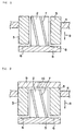
- Fig. 1 shows a cross section of a bearing according to the first preferred embodiment.
- a sleeve 3 is fitted on a column-like shaft 2 in such a manner as the sleeve 3 can rotate relative to the shaft 2.
- a rotor 4 (only a portion thereof is shown in Fig. 1) is attached to the sleeve 3.
- the sleeve 3 and the rotor 4 rotate about the shaft 2.
- a thrust plate 5 is fixed to one end of the shaft 2, and a hydrodynamic-pressure groove(s) 6 denoted by the dotted line for generating a thrust hydrodynamic pressure is formed on an end surface of the sleeve 3 facing the thrust plate 5.
- a groove or grooves 7 inclined with respect to an axis are formed on an outer circumferential surface of the shaft 2. The groove 7 is faced with an inner circumferential surface of the sleeve 3.
- rotational drive force is developed between a rotor magnet (not shown in Fig. 1) attached to the rotor 4 and a stator (not shown in Fig. 1) disposed on a fixed member, and the rotational drive force causes the rotor 4 and the sleeve 3 to rotate about the shaft 2. Due to relative rotation between the outer circumferential surface of the shaft 2 and the inner circumferential surface of the sleeve 3, a radial hydrodynamic pressure is developed between the two. On the other hand, due to relative rotation of the sleeve 3 and the thrust plate 5, a thrust hydrodynamic pressure is generated by the effect of the hydrodynamic-pressure groove(s) 6 of the thrust plate 5. As the result of both the radial hydrodynamic pressure and the thrust hydrodynamic pressure, the rotor 4 and the sleeve 3 rotate in non-contact condition against the shaft 2 and the thrust plate 5.
- the groove 7 inclined with respect to the axis is formed on the outer circumferential surface of the shaft 2.
- the sleeve 3 is structured so as to rotate counter-clockwise as viewed from the top. Further, the groove 7 is formed to run at an angle from the upper left-hand side toward the lower right-hand side on the front surface shown in Fig. 1.
- fluid such as air existing between the outer circumferential surface of the shaft 2 and the inner circumferential surface of the sleeve 3 flows from the upper left-hand side toward the lower right-hand side in Fig. 1, due to viscosity of the fluid.
- the thrust force urges the sleeve 3 against the thrust plate 5, whereby a gap in the thrust bearing portion is reduced.
- the hydrodynamic-pressure groove(s) 6 is formed in the thrust plate 5 and the thrust hydrodynamic pressure is therefore generated.
- the thrust hydrodynamic pressure balances with the thrust force, and the sleeve 3 and the thrust plate 5 consequently rotate close to each other in a non-contact condition, which in turn generates a high hydrodynamic pressure and enhances the rigidity of the thrust bearing portion.
- the groove 7 may be formed on the inner circumferential surface of the sleeve 3. That is, as in the previous example, the inner circumferential surface of the sleeve 3 may have a left-hand threaded groove so that urging force of the direction shown by the arrow 8 is generated and a similar effect to the above can be achieved.
- the hydrodynamic-pressure groove 6 of the thrust bearing portion is formed in the thrust plate 5 in the above preferred embodiment, the hydrodynamic-pressure groove 6 may be disposed to a bottom end surface of the sleeve 3 which is faced with the thrust plate 5.
- Fig. 2 shows a cross section of a bearing according to the second preferred embodiment.
- the like elements as in Fig. 1 bear the like reference numerals.
- a cover 9 for shielding an upper part of the shaft 2 from outside air is disposed above the sleeve 3 in Fig. 2.
- the direction in which the rotor 4 and the sleeve 3 rotate is the counter-clockwise direction as in the case of the first preferred embodiment.
- a groove 7 may be formed on the inner circumferential surface of the sleeve 3.
- the groove for generating a hydrodynamic pressure at the thrust bearing portion may be formed in the bottom end surface of the sleeve 3 which is faced with the thrust plate 5, instead of on the thrust plate 5.
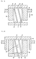
- Fig. 3 shows a cross section of a bearing according to the third preferred embodiment.
- the like elements as in Fig. 2 bear the like reference numerals.
- the direction in which the sleeve 3 rotates is also the counter-clockwise direction.
- the shaft 2 is fixed to the housing 1.
- the thrust plate 5 is fixed to an end surface of the sleeve 3, covering a top end of the shaft 2 with the sleeve 3 fitted on the shaft 2 for free rotation.
- the hydrodynamic-pressure groove 6 is formed on the surface of the thrust plate 5 which is opposed to a top end surface of the shaft 2.
- the opening 10 may be formed in the thrust plate 5, so that outside air may be introduced into the thrust bearing portion through it.
- the negative pressure effect described above would not be developed.
- the screw effect due to the groove 7 formed on the outer circumferential surface of the shaft 2 remains effective. Therefore, a force pressing down the sleeve 3 along the arrow 8 serves to make the gap of the thrust bearing portion narrower.
- the groove 7 may be formed on the inner circumferential surface of the sleeve 3. That is, the inner circumferential surface of the sleeve 3 may be left-hand threaded, so that urging thrust force similar to the above along the direction of the arrow 8 is generated.
- fluid running along the groove is guided in the radial bearing portion from the lower part to the upper part in Fig. 3.
- the opening 10 denoted by the dotted line, the fluid is discharged to outside through the thrust bearing portion connected with the radial bearing portion, after the fluid flows passed the radial bearing portion.
- the hydrodynamic-pressure groove 6 of the thrust bearing portion is formed on the thrust plate 5 in this preferred embodiment above, the hydrodynamic-pressure groove 6 may be formed on the top end surface of the shaft 2 which is faced with the thrust plate 5.
- Fig. 4 shows a cross section of a bearing according to the fourth preferred embodiment, wherein the shaft 2 rotates unlike in the first through the third preferred embodiments in which case require the sleeve 3 to rotate.
- the like elements as in Figs. 1 through 3 bear the like reference numerals.
- the thrust plate 5 is attached to the sleeve 3.
- the hydrodynamic-pressure groove 6 for generating a thrust hydrodynamic pressure is formed on the thrust plate 5.
- the shaft 2 having the groove 7 on the outer circumferential surface is fitted on the sleeve 3 for free rotation.
- the rotor 4 is fixed to the shaft 2, which allows the shaft 2 and the rotor 4 to rotate about the sleeve 3.
- the direction in which the shaft 2 and the rotor 4 rotate is the counter-clockwise direction as viewed from top, as in the precedent preferred embodiments.
- an opening 10 may be formed in the thrust plate 6 to thereby introduce outside air.
- the screw effect due to the groove 7 formed on the outer circumferential surface of the shaft 2 remains effective, which allows the force pressing down the shaft 2 as denoted by the arrow 8 to function, and hence, brings the gap of the thrust bearing portion closer.
- the groove 7 may be formed on the inner circumferential surface of the sleeve 3, instead of forming the groove 7 on the outer circumferential surface of the shaft 2. That is, the inner circumferential surface of the sleeve 3 may be left-hand threaded, so that urging force along the arrow 8 similar to the above is generated.
- the fluid flowing along the groove is introduced at the upper part of the radial bearing portion and guided toward the lower part of the radial bearing portion in Fig. 4.
- an opening 10 denoted by the dotted line after the fluid flows passed the radial bearing portion, the fluid is discharged to outside through the thrust bearing portion connected with the radial bearing portion. With the diameter of the opening 10 appropriately selected, the pressure of the fluid generates force which lifts up the shaft 2 and the rotor 4 with respect to the thrust plate 5, and therefore, the thrust hydrodynamic-pressure groove may be eliminated. It would be more effective if this is realized.
- the hydrodynamic-pressure groove 6 of the thrust bearing portion formed in the thrust plate 5 may be formed on the opposing bottom end surface of the shaft 2.
- Fig. 5 shows a cross section of a bearing according to the fifth preferred embodiment.
- the shaft 2 rotates relative to the sleeve 3
- the thrust bearing portion is disposed in an upper part of the bearing in Fig. 5.
- the like elements as in Figs. 1 through 4 bear the like reference numerals.
- the direction in which the shaft 2 rotates is the counter-clockwise direction, as in the case of precedent preferred embodiments.
- the groove 7 disposed to the shaft 2 is a so-called herringbone-shaped groove, rather than an inclined groove as described in the other embodiments.
- An inclined groove and a herringbone-shaped groove are interchangeable with each other in all of the preferred embodiments.
- a herringbone-shaped groove is normally grooves which are inclined in two different directions, and defines a mountain-shaped apex at a portion where the two grooves meet each other. In Fig. 5, the location of the mountain-shaped apex is deviated from the axial center of the bearing portion. With respect to suction effect of fluid in the groove 7 formed in such a manner, a part of the groove occupying wider span in the axial direction demonstrates superior sucking effect to the other part of the groove.
- the groove may have other shape, such as a wave-like shape or a hook-like shape, so far as the groove subjects the shaft 2 and the sleeve 3 to a thrust effect relative to each other in a direction pressing one of the both thrust bearing members toward the other, and the groove having any other such shape would fall within the scope of the present invention.
- the rotation of the shaft 2 generates a negative pressure in the vicinity of the lower portion of the shaft 2 which is shielded from outside air.
- Suction force induced by the negative pressure develops thrust force which presses down the shaft 2 along the arrow 8.
- the left-hand screw effect of the herringbone-shaped groove similarly generates a force which presses down the shaft 2.
- the hydrodynamic-pressure groove 6 generates a thrust hydrodynamic pressure surpassing these forces.
- the opening 10 denoted by the dotted line is disposed, the negative pressure effect described above is not generated.
- the downward pressing force along the arrow 8 due to the screw effect remains effective, whereby the gap at the thrust bearing portion is narrowed.
- the effect achieved by disposing the opening 10 resides in that an simplification can be realized by eliminating the hydrodynamic-pressure groove 6, due to the effect of the fluid sucked through the opening 10.
- the fluid sucked through the opening 10 flows to the radial bearing portion along the groove 7 and then to the thrust bearing portion connected with the radial bearing portion, and thereby generates the thrust fluid pressure which lifts up the thrust plate 5 from the top end surface of the sleeve 3.
- the groove 7 may be formed on the inner circumferential surface of the sleeve 3, rather than forming on the outer circumferential surface of the shaft 2, to thereby generate downward pressing force along the arrow 8 similar to the above.
- air running along the groove 7 is introduced at the upper part of the thrust bearing portion and guided to the lower part of the radial bearing portion as viewed in the drawing, and therefore, an undesired air-cushion effect is created. With the opening 10 described above disposed, it is possible to avoid this cushion effect.
- the hydrodynamic pressure generating groove 6 of the thrust bearing portion is formed in the thrust plate 5 in the fifth preferred embodiment as well, the groove may be formed on the top end surface of the sleeve 3 opposing to the thrust plate 5.
- fluid such as air is used to develop a hydrodynamic pressure at the bearing.
- the fluid herein referred to includes other gases for creating a particular atmosphere, such as inert gas and nitrogen gas, as well as liquids such as oil.
- the dimensions of the respective portions were, diameter of the radial bearing : 15 mm, length of the radial bearing : 20 mm, and diameter of the thrust plate : 23 mm.
- the dimensions of the radial bearing portion were, diameter : 15 mm, and length : 20 mm.
- the dimensions of the radial bearing portion were, diameter : 15 mm, and length : 20 mm.
- the dimensions of the radial bearing portion were, diameter : 15 mm, and length : 20 mm.
Landscapes
- Engineering & Computer Science (AREA)
- General Engineering & Computer Science (AREA)
- Mechanical Engineering (AREA)
- Physics & Mathematics (AREA)
- Fluid Mechanics (AREA)
- Power Engineering (AREA)
- Chemical & Material Sciences (AREA)
- Oil, Petroleum & Natural Gas (AREA)
- Sliding-Contact Bearings (AREA)
- Connection Of Motors, Electrical Generators, Mechanical Devices, And The Like (AREA)
Abstract
Description
- The present invention relates to a hydrodynamic bearing and a spindle motor comprising the same. Such a spindle motor is used as a driving source for a magnetic recording apparatus such as a hard disk, or a bar code scanner, and the like.
- Important characteristics for a bearing of a spindle motor used for magnetic recording apparatus such as a hard disk, or a bar code scanner, etc. are wear and abrasion resistance, vibration resistance, stability of rotation, and the like. Particularly, when rotating members and fixed members of the bearing contact with each other due to vibration, rotation of the spindle motor becomes unstable, which in turn seriously influences reliability and durability of the bearing. In order to avoid this, a technology for enhancing the thrust rigidity of a bearing is in demand.
- Fig. 6 shows a hydrodynamic bearing disclosed in Japanese Patent Kokai (A) Publication No. 69715/1999, which could be one of solutions for the above problem. In Fig. 6, a
shaft 12 is fixed to ahousing 11. Acylindrical member 13 with a closed end on one side is fitted on an outer circumferential surface of theshaft 12 such that thecylindrical member 13 freely rotates. These two members form a bearing. A so called herringbone-shaped groove is formed on the outer circumferential surface of theshaft 12. - A
rotor magnet 15 is attached to an outer periphery of thecylindrical member 13, and astator 14 which forms an electro-magnet is attached to thehousing 11 so as to face therotor magnet 15. As a coil wound around thestator 14 is energized, attraction/repellence force is developed between thestator 14 and therotor magnet 15, which in turn drives the spindle motor. With thecylindrical member 13 rotating due to the driving force, relative motion between the outer circumferential surface of theshaft 12 and a facing inner circumferential surface of the cylindrical member 13 (i.e., radial bearing portion) is developed, which generates a radial hydrodynamic pressure. Air is introduced by an effect of the herringbone-shaped groove formed on the outer circumferential surface of theshaft 12, and is guided to the area between the closed end of thecylindrical member 13 and an upper surface of the shaft 12 (i.e., thrust bearing portion), and applies a pressure. As a result, thecylindrical member 13 is lifted up relative to theshaft 12. - A ring-
shaped thrust member 16 is disposed to an outer circumferential portion of thecylindrical member 13, while athrust retaining member 17 is disposed to thehousing 11 at a position opposed to thethrust member 16. As thecylindrical member 13 is lifted up, thethrust member 16 moves closer to thethrust retaining member 17, and a thrust hydrodynamic pressure is generated between the two. This thrust hydrodynamic pressure balances with the pressure generated at the thrust bearing portion, whereby the bearing rotates stably in a non-contact condition. - However, in the case of the hydrodynamic bearing disclosed in Japanese Patent Kokai (A) Publication No. 69715/1999, it is difficult to accurately adjust the squareness of the
thrust member 16 and a gap with thethrust retaining member 17 after thecylindrical member 13 is inserted during assembly process. Further, since thethrust member 16 and thethrust retaining member 17 are additionally disposed, the structure becomes more complex, larger and heavier. - The purpose of the present invention is, therefore, to provide a bearing which solves the problem as described above, and which can be assembled into a simple structure with a high thrust rigidity and can obtain stable rotation.
- According to the present invention, a groove or grooves are formed on either an outer circumferential surface of a shaft or an inner circumferential surface of a sleeve, and the groove develops a thrust force to cause the gap between the two members facing each other at the thrust bearing portion narrower, to thereby solve the problem mentioned in the above. Specifically, the present invention includes the following.
- That is, one aspect of the present invention is a hydrodynamic bearing comprising: a shaft; a sleeve being fitted on an outer circumferential surface of the shaft such that the sleeve freely rotates relative to the shaft; and a thrust plate being directly or indirectly attached to or integrated with either one of the shaft and said sleeve, and the thrust plate being faced with a plane perpendicular to an axis which is formed at one end of the other one of the shaft and the sleeve, wherein hydrodynamic pressure in a radial direction is generated between an outer circumferential surface of the shaft and an inner circumferential surface of the sleeve (hereinafter referred to as "radial bearing portion"), and hydrodynamic pressure in a thrust direction is generated between the thrust plate and the plane perpendicular to said axis which is formed at said one end of the other member and is faced with the thrust plate (hereinafter referred to as "thrust bearing portion"), and the hydrodynamic bearing is characterized in that either one surface forming the radial bearing portion is provided with a groove or grooves for generating a thrust force in a direction making the two facing members at the thrust bearing portion closer to each other, and that either one of the surfaces facing each other at the thrust bearing portion is provided with a groove or grooves for generating hydrodynamic pressure in the thrust direction.
- Another aspect of the hydrodynamic bearing according to the present invention is characterized in that the groove formed in the radial bearing portion is a groove inclined with respect to the axis of the bearing or a herringbone-shaped groove.
- Yet another aspect of the hydrodynamic bearing according to the present invention is characterized in that the upstream side of the radial bearing portion is shielded against outside atmosphere, and utilizing resultant negative pressure in the vicinity of the upstream of the radial bearing portion for enhancing the force in a direction urging the members forming the thrust bearing portion toward each other.
- Yet another aspect of the hydrodynamic bearing according to the present invention is characterized in that the radial bearing portion connected with outside atmosphere and the thrust bearing portion connected with outside atmosphere are formed contiguous to each other, and utilizing gas introduced at the radial bearing portion as a thrust pressure at the thrust bearing portion so as to eliminate the groove for generating the hydrodynamic pressure at the thrust bearing portion.
- Still another aspect of the hydrodynamic bearing according to the present invention is characterized in that the hydrodynamic bearing is a shaft rotation type.
- Further covered in the present invention is a spindle motor which comprises a hydrodynamic bearing according to the present invention.
- In the radial bearing portion, urging force is developed in a thrust direction which reduces a gap between the members forming the thrust bearing portion, and the urging force balances with the thrust pressure generated at the thrust bearing portion. This creates an effect that the thrust rigidity of the bearing is enhanced and a variation in thrust position is reduced. Hence, a hydrodynamic bearing according to the present invention is excellent in that the thrust rigidity is high, the resistant against vibration is strong, and the structure is simple and in turn easy to assemble.
- By utilizing the negative pressure generated as a result of shielding the radial bearing portion, it is possible to further intensify the force in the thrust direction to reduce the gap in the thrust bearing portion.
- In addition, as air introduced at the radial bearing portion is guided to the thrust bearing portion connected with the radial bearing portion, and preferably discharged to outside, it is possible to eliminate a process of forming a groove for generating the thrust hydrodynamic pressure in the thrust bearing portion by utilizing the pressure induced by the introduced air,.
-
- Fig. 1 is a cross sectional view of a hydrodynamic bearing according to a preferred embodiment of the present invention;
- Fig. 2 is a cross sectional view of a hydrodynamic bearing according to another preferred embodiment of the present invention;
- Fig. 3 is a cross sectional view of a hydrodynamic bearing according to yet another preferred embodiment of the present invention;
- Fig. 4 is a cross sectional view of a hydrodynamic bearing according to yet another preferred embodiment of the present invention;
- Fig. 5 is a cross sectional view of a hydrodynamic bearing according to still another preferred embodiment of the present invention; and
- Fig. 6 is a cross sectional view of a spindle motor which uses a conventional hydrodynamic bearing.
-
- According to the present invention, a groove or grooves inclined with respect to an axis are formed on one of surfaces defining a radial bearing portion of a hydrodynamic bearing, which is either an outer circumferential surface of a shaft or an inner circumferential surface of a sleeve. Alternatively, a groove or grooves of a different type having a similar effect could be formed, as described later. Due to the effect of the groove, a thrust force which moves either one of the shaft and the sleeve axially relative to the other is developed. By utilizing the thrust force and thereby urging mutually facing members at a thrust bearing portion toward each other, stable bearing rotation is realized. The thrust bearing portion is structured to generate hydrodynamic pressure sufficient enough to surpass this thrust force, so that the bearing can rotate in a non-contact condition. More specifically, a groove or grooves for generating a thrust hydrodynamic pressure are formed on a surface of either one of the members facing each other at the thrust bearing portion. Alternatively, air may be guided from the radial bearing portion to the thrust bearing portion, thereby using the air as a pressure to keep the thrust bearing portion in a non-contact condition.
- The first preferred embodiment of the present invention will be described by referring to the associated drawing. Fig. 1 shows a cross section of a bearing according to the first preferred embodiment. In Fig. 1, a
sleeve 3 is fitted on a column-like shaft 2 in such a manner as thesleeve 3 can rotate relative to theshaft 2. A rotor 4 (only a portion thereof is shown in Fig. 1) is attached to thesleeve 3. In the structure shown in Fig. 1, thesleeve 3 and therotor 4 rotate about theshaft 2. Athrust plate 5 is fixed to one end of theshaft 2, and a hydrodynamic-pressure groove(s) 6 denoted by the dotted line for generating a thrust hydrodynamic pressure is formed on an end surface of thesleeve 3 facing thethrust plate 5. A groove orgrooves 7 inclined with respect to an axis are formed on an outer circumferential surface of theshaft 2. Thegroove 7 is faced with an inner circumferential surface of thesleeve 3. - With respect to an operation of the bearing structured as described in the above, rotational drive force is developed between a rotor magnet (not shown in Fig. 1) attached to the
rotor 4 and a stator (not shown in Fig. 1) disposed on a fixed member, and the rotational drive force causes therotor 4 and thesleeve 3 to rotate about theshaft 2. Due to relative rotation between the outer circumferential surface of theshaft 2 and the inner circumferential surface of thesleeve 3, a radial hydrodynamic pressure is developed between the two. On the other hand, due to relative rotation of thesleeve 3 and thethrust plate 5, a thrust hydrodynamic pressure is generated by the effect of the hydrodynamic-pressure groove(s) 6 of thethrust plate 5. As the result of both the radial hydrodynamic pressure and the thrust hydrodynamic pressure, therotor 4 and thesleeve 3 rotate in non-contact condition against theshaft 2 and thethrust plate 5. - As described in the above, the
groove 7 inclined with respect to the axis is formed on the outer circumferential surface of theshaft 2. According to the first preferred embodiment shown in the Fig. 1, thesleeve 3 is structured so as to rotate counter-clockwise as viewed from the top. Further, thegroove 7 is formed to run at an angle from the upper left-hand side toward the lower right-hand side on the front surface shown in Fig. 1. When thesleeve 3 is in rotation, because of theinclined groove 7, fluid such as air existing between the outer circumferential surface of theshaft 2 and the inner circumferential surface of thesleeve 3 flows from the upper left-hand side toward the lower right-hand side in Fig. 1, due to viscosity of the fluid. The flow of the fluid and the viscosity of the fluid develop thrust force to thesleeve 3, which urges thesleeve 3 downwardly against thethrust plate 5 as denoted by anarrow 8 in the drawing. This can be easily understood as screwing thesleeve 3 counter-clockwise into a left-hand screw defined along thegroove 7 formed on theshaft 2. - The thrust force urges the
sleeve 3 against thethrust plate 5, whereby a gap in the thrust bearing portion is reduced. As described in the above, the hydrodynamic-pressure groove(s) 6 is formed in thethrust plate 5 and the thrust hydrodynamic pressure is therefore generated. The thrust hydrodynamic pressure balances with the thrust force, and thesleeve 3 and thethrust plate 5 consequently rotate close to each other in a non-contact condition, which in turn generates a high hydrodynamic pressure and enhances the rigidity of the thrust bearing portion. - Although the foregoing has described that the
radial groove 7 is formed on the outer circumferential surface of theshaft 2, thegroove 7 may be formed on the inner circumferential surface of thesleeve 3. That is, as in the previous example, the inner circumferential surface of thesleeve 3 may have a left-hand threaded groove so that urging force of the direction shown by thearrow 8 is generated and a similar effect to the above can be achieved. - As the
groove 7 is formed, fluid such as air is sucked at an upper part of the radial bearing portion in Fig. 1 and flows downwardly along theinclined groove 7. Therefore, in the case of the bearing having the structure shown in Fig. 1 wherein the radial bearing portion and the thrust bearing portion are contiguous to each other, the fluid flowing passed the radial bearing portion streams into the thrust bearing portion. As a result of this, the fluid contained to the thrust bearing portion acts as a pressure to pull the members forming the thrust bearing portion apart from each other, and hence, it may be possible to obtain enough thrust pressure even if the hydrodynamic-pressure groove 6 on thethrust plate 5 is eliminated. It would be more effective if this is realized. - When the
groove 7 is disposed to thesleeve 3, even if the groove is equally left-hand threaded, air is sucked from the lower part of Fig. 1 (thrust bearing portion) and is guided upwardly and discharged from the upper part of the radial bearing portion. Accordingly, a pressure as mentioned in the above to pull apart the thrust bearing portion is not created, and hence, the hydrodynamic-pressure groove 6 can not be eliminated in this case. - Although the hydrodynamic-
pressure groove 6 of the thrust bearing portion is formed in thethrust plate 5 in the above preferred embodiment, the hydrodynamic-pressure groove 6 may be disposed to a bottom end surface of thesleeve 3 which is faced with thethrust plate 5. - Now, the second preferred embodiment of the present invention will be described by referring to the associated drawing. Fig. 2 shows a cross section of a bearing according to the second preferred embodiment. In Fig. 2, the like elements as in Fig. 1 bear the like reference numerals. According to the second preferred embodiment, a
cover 9 for shielding an upper part of theshaft 2 from outside air is disposed above thesleeve 3 in Fig. 2. The direction in which therotor 4 and thesleeve 3 rotate is the counter-clockwise direction as in the case of the first preferred embodiment. - In the hydrodynamic bearing structured as described in the above, as the
sleeve 3 rotates, fluid, such as air, flows in the radial bearing portion along thegroove 7 of theshaft 2 from the upper part to the lower part in Fig. 2, as described earlier. However, since the upper part of thesleeve 3 is sealed off with thecover 9, the flow of the fluid generates a negative pressure in the vicinity of thecover 9. Suction force induced by this negative pressure intensifies the urging force denoted by thearrow 8. Since the hydrodynamic-pressure groove 6 develops a thrust hydrodynamic pressure surpassing this suction force at the thrust bearing portion, it is possible to obtain stable rotation with the thrust bearing portion keeping non-contact condition and maintaining the gap therein narrow. - In the second preferred embodiment as well, a
groove 7 may be formed on the inner circumferential surface of thesleeve 3. In such a case, as thesleeve 3 rotates, fluid is guided in the radial bearing portion from the lower part to the upper part in Fig. 1, and further, toward the thrust bearing portion which is connected with the radial bearing portion. However, since that thrust bearing portion is shielded with thecover 9, the fluid is compressed in the vicinity of thecover 9, which in turn may lead to an undesired air-cushion effect. By forming anopening 10 as denoted by the dotted line in thecover 9, the air-cushion effect may be avoided even in such a case. - Further, in the second preferred embodiment as well, the groove for generating a hydrodynamic pressure at the thrust bearing portion may be formed in the bottom end surface of the
sleeve 3 which is faced with thethrust plate 5, instead of on thethrust plate 5. - Now, the third preferred embodiment of the present invention will be described by referring to the associated drawing. Fig. 3 shows a cross section of a bearing according to the third preferred embodiment. In Fig. 3, the like elements as in Fig. 2 bear the like reference numerals. Further, the direction in which the
sleeve 3 rotates is also the counter-clockwise direction. In Fig. 3, theshaft 2 is fixed to thehousing 1. Thethrust plate 5 is fixed to an end surface of thesleeve 3, covering a top end of theshaft 2 with thesleeve 3 fitted on theshaft 2 for free rotation. The hydrodynamic-pressure groove 6 is formed on the surface of thethrust plate 5 which is opposed to a top end surface of theshaft 2. - In the hydrodynamic bearing structured as described in the above, as the
sleeve 3 rotates, fluid flows in the radial bearing portion along thegroove 7 of theshaft 2 from the upper part to the lower part in Fig. 3. However, since the upper part is shielded by thethrust plate 5 from outside atmosphere, a negative pressure is generated in the vicinity of thethrust plate 5. This negative pressure generates thrust force which presses down thesleeve 3 along thearrow 8, thereby reducing a gap of the thrust bearing portion between thethrust plate 5 and the top end surface of theshaft 2. The thrust bearing portion is structured so as to generate a thrust hydrodynamic pressure surpassing this thrust force by the effect of the hydrodynamic-pressure groove 6. - As denoted by the dotted line, the
opening 10 may be formed in thethrust plate 5, so that outside air may be introduced into the thrust bearing portion through it. In this case, the negative pressure effect described above would not be developed. However, the screw effect due to thegroove 7 formed on the outer circumferential surface of theshaft 2 remains effective. Therefore, a force pressing down thesleeve 3 along thearrow 8 serves to make the gap of the thrust bearing portion narrower. - In the third preferred embodiment as well, the
groove 7 may be formed on the inner circumferential surface of thesleeve 3. That is, the inner circumferential surface of thesleeve 3 may be left-hand threaded, so that urging thrust force similar to the above along the direction of thearrow 8 is generated. In this case, fluid running along the groove is guided in the radial bearing portion from the lower part to the upper part in Fig. 3. By forming theopening 10 denoted by the dotted line, the fluid is discharged to outside through the thrust bearing portion connected with the radial bearing portion, after the fluid flows passed the radial bearing portion. Since a pressure which lifts up thethrust plate 5 and thesleeve 3 from the top end portion of theshaft 2 is generated at the thrust bearing portion, it may be possible to eliminate the thrust hydrodynamic-pressure groove in this case. It would be more effective, if this is realized. - Although the hydrodynamic-
pressure groove 6 of the thrust bearing portion is formed on thethrust plate 5 in this preferred embodiment above, the hydrodynamic-pressure groove 6 may be formed on the top end surface of theshaft 2 which is faced with thethrust plate 5. - Now, the fourth preferred embodiment of the present invention will be described by referring to the associated drawing. Fig. 4 shows a cross section of a bearing according to the fourth preferred embodiment, wherein the
shaft 2 rotates unlike in the first through the third preferred embodiments in which case require thesleeve 3 to rotate. In Fig. 4, the like elements as in Figs. 1 through 3 bear the like reference numerals. In Fig. 4, thethrust plate 5 is attached to thesleeve 3. The hydrodynamic-pressure groove 6 for generating a thrust hydrodynamic pressure is formed on thethrust plate 5. Theshaft 2 having thegroove 7 on the outer circumferential surface is fitted on thesleeve 3 for free rotation. Therotor 4 is fixed to theshaft 2, which allows theshaft 2 and therotor 4 to rotate about thesleeve 3. The direction in which theshaft 2 and therotor 4 rotate is the counter-clockwise direction as viewed from top, as in the precedent preferred embodiments. - In the hydrodynamic bearing structured as described in the above, as the
shaft 2 rotates, fluid flows from a lower portion toward an upper portion in Fig. 4 along thegroove 7. However, since the lower portion is shielded by thethrust plate 5 from outside atmosphere, a negative pressure is generated in the vicinity of thethrust plate 5. Suction force of the negative pressure generates force which presses down theshaft 2 along thearrow 8, thereby reducing a gap of the thrust bearing portion between thethrust plate 5 and the bottom end surface of theshaft 2. The thrust bearing portion is structured so as to generate a thrust hydrodynamic pressure surpassing the above generated force by the effect of the hydrodynamic-pressure groove 6. Further, due to a screwing effect created by thegroove 7 formed in a left-hand screw manner, a force presses down theshaft 2 toward thethrust plate 5 is added. - As denoted by the dotted line, an
opening 10 may be formed in thethrust plate 6 to thereby introduce outside air. In this case, while the effect caused by the negative pressure described above is not valid, the screw effect due to thegroove 7 formed on the outer circumferential surface of theshaft 2 remains effective, which allows the force pressing down theshaft 2 as denoted by thearrow 8 to function, and hence, brings the gap of the thrust bearing portion closer. - In this structure as well, the
groove 7 may be formed on the inner circumferential surface of thesleeve 3, instead of forming thegroove 7 on the outer circumferential surface of theshaft 2. That is, the inner circumferential surface of thesleeve 3 may be left-hand threaded, so that urging force along thearrow 8 similar to the above is generated. In this case, the fluid flowing along the groove is introduced at the upper part of the radial bearing portion and guided toward the lower part of the radial bearing portion in Fig. 4. By forming anopening 10 denoted by the dotted line, after the fluid flows passed the radial bearing portion, the fluid is discharged to outside through the thrust bearing portion connected with the radial bearing portion. With the diameter of theopening 10 appropriately selected, the pressure of the fluid generates force which lifts up theshaft 2 and therotor 4 with respect to thethrust plate 5, and therefore, the thrust hydrodynamic-pressure groove may be eliminated. It would be more effective if this is realized. - In the fourth preferred embodiment as well, as in the precedent embodiments, the hydrodynamic-
pressure groove 6 of the thrust bearing portion formed in thethrust plate 5 may be formed on the opposing bottom end surface of theshaft 2. - Now, the fifth preferred embodiment of the present invention will be described by referring to the associated drawing. Fig. 5 shows a cross section of a bearing according to the fifth preferred embodiment. Although it is structured that the
shaft 2 rotates relative to thesleeve 3, this is different from the fourth preferred embodiment in that the thrust bearing portion is disposed in an upper part of the bearing in Fig. 5. In Fig. 5, the like elements as in Figs. 1 through 4 bear the like reference numerals. Further, the direction in which theshaft 2 rotates is the counter-clockwise direction, as in the case of precedent preferred embodiments. - In the fifth preferred embodiment, the
groove 7 disposed to theshaft 2 is a so-called herringbone-shaped groove, rather than an inclined groove as described in the other embodiments. An inclined groove and a herringbone-shaped groove are interchangeable with each other in all of the preferred embodiments. A herringbone-shaped groove is normally grooves which are inclined in two different directions, and defines a mountain-shaped apex at a portion where the two grooves meet each other. In Fig. 5, the location of the mountain-shaped apex is deviated from the axial center of the bearing portion. With respect to suction effect of fluid in thegroove 7 formed in such a manner, a part of the groove occupying wider span in the axial direction demonstrates superior sucking effect to the other part of the groove. In short, in Fig. 5, the effect of the part of the groove formed in the left-hand screw direction at a lower axial part is superior. Hence, as theshaft 2 rotates counter-clockwise, theshaft 2 exerts urging force along the direction of thearrow 8 over thesleeve 3, thereby creating force of a direction which makes the gap of the thrust bearing portion narrower. - While the respective preferred embodiments of the present invention relate to the examples of an inclined groove and a herringbone-shaped groove, the groove may have other shape, such as a wave-like shape or a hook-like shape, so far as the groove subjects the
shaft 2 and thesleeve 3 to a thrust effect relative to each other in a direction pressing one of the both thrust bearing members toward the other, and the groove having any other such shape would fall within the scope of the present invention. - In the hydrodynamic bearing structured as described in the above, just like the precedent preferred embodiments exemplified before, the rotation of the
shaft 2 generates a negative pressure in the vicinity of the lower portion of theshaft 2 which is shielded from outside air. Suction force induced by the negative pressure develops thrust force which presses down theshaft 2 along thearrow 8. Further, the left-hand screw effect of the herringbone-shaped groove similarly generates a force which presses down theshaft 2. At the thrust bearing portion, the hydrodynamic-pressure groove 6 generates a thrust hydrodynamic pressure surpassing these forces. Where theopening 10 denoted by the dotted line is disposed, the negative pressure effect described above is not generated. However, the downward pressing force along thearrow 8 due to the screw effect remains effective, whereby the gap at the thrust bearing portion is narrowed. - The effect achieved by disposing the
opening 10 resides in that an simplification can be realized by eliminating the hydrodynamic-pressure groove 6, due to the effect of the fluid sucked through theopening 10. The fluid sucked through theopening 10 flows to the radial bearing portion along thegroove 7 and then to the thrust bearing portion connected with the radial bearing portion, and thereby generates the thrust fluid pressure which lifts up thethrust plate 5 from the top end surface of thesleeve 3. - In this structure as well, the
groove 7 may be formed on the inner circumferential surface of thesleeve 3, rather than forming on the outer circumferential surface of theshaft 2, to thereby generate downward pressing force along thearrow 8 similar to the above. In this case, air running along thegroove 7 is introduced at the upper part of the thrust bearing portion and guided to the lower part of the radial bearing portion as viewed in the drawing, and therefore, an undesired air-cushion effect is created. With theopening 10 described above disposed, it is possible to avoid this cushion effect. - Although the hydrodynamic
pressure generating groove 6 of the thrust bearing portion is formed in thethrust plate 5 in the fifth preferred embodiment as well, the groove may be formed on the top end surface of thesleeve 3 opposing to thethrust plate 5. - In each one of the preferred embodiments above, fluid such as air is used to develop a hydrodynamic pressure at the bearing. The fluid herein referred to includes other gases for creating a particular atmosphere, such as inert gas and nitrogen gas, as well as liquids such as oil.
- A performance was evaluated for the sleeve-rotation type bearing structured as shown in Fig. 1.
- Conditions were, rotor weight : 100 g, rotation speed : 12,000 rpm, and the clearance : 4 µm. These conditions remain the same for the other examples shown below.
- The dimensions of the respective portions were, diameter of the radial bearing : 15 mm, length of the radial bearing : 20 mm, and diameter of the thrust plate : 23 mm.
- The result of the evaluation for this example:
- Property 1 : Ratio of relative assembly time was 120 (with excellent squareness of the axis end and the sleeve end).
- Property 2 : Excellent rotation capability. Contact occurred at 5G.
-
- A performance was evaluated for the sleeve-rotation type bearing structured as shown in Fig. 3.
- The dimensions of the radial bearing portion were, diameter : 15 mm, and length : 20 mm.
- Property 1 : Ratio of relative assembly time was 120 (with excellent squareness of the axis end and the sleeve end)
- Property 2 : Excellent rotation capability. Contact occurred at 10G.
-
- A performance was evaluated for the shaft-rotation type bearing structured as shown in Fig. 4.
- The dimensions of the radial bearing portion were, diameter : 15 mm, and length : 20 mm.
- Property 1 : Ratio of relative assembly time was 100 (with excellent squareness of the axis end and the sleeve end)
- Property 2 : Excellent rotation capability. Contact occurred at 9G.
-
- A performance was evaluated for the shaft-rotation type bearing structured as shown in Fig. 5.
- The dimensions of the radial bearing portion were, diameter : 15 mm, and length : 20 mm.
- Property 1 : Ratio of relative assembly time was 100 (with excellent squareness of the axis end and the sleeve end)
- Property 2 : Excellent rotation capability. Contact occurred at 6G.
-
- A performance was evaluated for the conventional shaft-rotation type bearing with closed axis end structured as shown in Fig. 6.
- Property 1 : Ratio of relative assembly time was 200 (with difficulty in adjustment)
- Property 2 : Excellent rotation stability.
-
Claims (6)
- A hydrodynamic bearing, comprising:a column-like shaft (2);a hollow cylindrical sleeve (3) being fitted on an outer circumferential surface of said shaft (2) so as to achieve relative rotation among the two; anda thrust plate (5) being directly or indirectly attached to or integrated with either one of said shaft (2) and said sleeve (3), which thrust plate (5) being faced with a plane formed at one end of the other one of said shaft (2) and said sleeve (3) perpendicular to an axis of the said bearing,
wherein hydrodynamic pressure in a radial direction is generated at a radial bearing portion formed by an outer circumferential surface of said shaft (2) and an inner circumferential surface of said sleeve (3), and hydrodynamic pressure in a thrust direction is generated at a thrust bearing portion formed by said thrust plate (5) and said plane which is faced with said thrust plate (5) and formed at said one end of said other member perpendicular to said axis,the hydrodynamic bearing is characterized in that either one of the surfaces forming said radial bearing portion is provided with a groove or grooves (7) which generate a force in a thrust direction so as to make the two facing members at said thrust bearing portion closer to each other, andeither one of the surfaces of said two facing members at said thrust bearing portion is provided with a groove or grooves (6) which generate hydrodynamic pressure in said thrust direction. - The hydrodynamic bearing of claim 1, wherein said groove (7) formed in said radial bearing portion is either a groove inclined with respect to said axis, or a herringbone-shaped groove.
- The hydrodynamic bearing of claim 1 or 2, wherein an upstream side of said radial bearing portion is shielded against outside atmosphere, anda resultant negative pressure developed in the vicinity of said upstream side of said radial bearing portion is utilized for enhancing said force in a thrust direction of bringing the two facing members forming said thrust bearing portion closer to each other.
- The hydrodynamic bearing of claim 1 or 2, wherein the radial bearing portion connected with outside atmosphere and the thrust bearing portion connected with outside atmosphere are formed contiguous to each other, and utilize gas introduced at said radial bearing portion for a thrust pressure at said thrust bearing portion, whereby said groove(s) (6) for generating the hydrodynamic pressure at said thrust bearing portion is eliminated.
- The hydrodynamic bearing of any one of claims 1 through 4, wherein the hydrodynamic bearing is structured as a shaft-rotation type.
- A spindle motor comprising the hydrodynamic bearing of claims 1 through 5.
Applications Claiming Priority (3)
| Application Number | Priority Date | Filing Date | Title |
|---|---|---|---|
| JP12423299 | 1999-04-30 | ||
| JP11124232A JP2000314417A (en) | 1999-04-30 | 1999-04-30 | Dynamic pressure bearing with increased thrust rigidity |
| PCT/JP2000/002829 WO2000066902A1 (en) | 1999-04-30 | 2000-04-28 | Dynamic pressure bearing and spindle motor with the bearing |
Publications (3)
| Publication Number | Publication Date |
|---|---|
| EP1099867A1 true EP1099867A1 (en) | 2001-05-16 |
| EP1099867A4 EP1099867A4 (en) | 2006-08-09 |
| EP1099867B1 EP1099867B1 (en) | 2009-12-23 |
Family
ID=14880256
Family Applications (1)
| Application Number | Title | Priority Date | Filing Date |
|---|---|---|---|
| EP00922905A Expired - Lifetime EP1099867B1 (en) | 1999-04-30 | 2000-04-28 | Dynamic pressure bearing and spindle motor with the bearing |
Country Status (5)
| Country | Link |
|---|---|
| US (1) | US6870289B1 (en) |
| EP (1) | EP1099867B1 (en) |
| JP (1) | JP2000314417A (en) |
| DE (1) | DE60043568D1 (en) |
| WO (1) | WO2000066902A1 (en) |
Cited By (1)
| Publication number | Priority date | Publication date | Assignee | Title |
|---|---|---|---|---|
| RU2247876C2 (en) * | 2002-03-15 | 2005-03-10 | Закрытое акционерное общество "Анкон-Т" | Radial thrust bearing |
Families Citing this family (3)
| Publication number | Priority date | Publication date | Assignee | Title |
|---|---|---|---|---|
| JP4994937B2 (en) * | 2007-05-07 | 2012-08-08 | 日立粉末冶金株式会社 | Sintered oil-impregnated bearing for fan motor |
| US8616772B1 (en) | 2013-03-15 | 2013-12-31 | Little Engine, LLC | Conformal wear-resistant bearing assembly |
| CN108253012A (en) * | 2017-12-13 | 2018-07-06 | 湖南大学 | A kind of method for improving air foil bearing supporting rotor system stability |
Family Cites Families (6)
| Publication number | Priority date | Publication date | Assignee | Title |
|---|---|---|---|---|
| JPS5892516U (en) | 1981-12-18 | 1983-06-23 | 日本精工株式会社 | Dynamic pressure bearing device for rotating units |
| JPS5968716A (en) | 1982-10-12 | 1984-04-18 | Toshiba Corp | Rotary body supporting device |
| US5559382A (en) | 1992-10-01 | 1996-09-24 | Nidec Corporation | Spindle motor |
| JP3184787B2 (en) | 1997-08-13 | 2001-07-09 | セイコーインスツルメンツ株式会社 | Air dynamic pressure bearing, spindle motor, and rotating device using the spindle motor as a driving source of the rotating body |
| JP3652875B2 (en) * | 1998-03-26 | 2005-05-25 | 日本電産株式会社 | motor |
| US6121703A (en) * | 1998-06-30 | 2000-09-19 | Seagate Technology, Inc. | Fluid dynamic bearing motor design for mounting a rotating shaft directly into a base casting |
-
1999
- 1999-04-30 JP JP11124232A patent/JP2000314417A/en active Pending
-
2000
- 2000-04-28 DE DE60043568T patent/DE60043568D1/en not_active Expired - Lifetime
- 2000-04-28 WO PCT/JP2000/002829 patent/WO2000066902A1/en not_active Ceased
- 2000-04-28 EP EP00922905A patent/EP1099867B1/en not_active Expired - Lifetime
- 2000-04-28 US US09/720,671 patent/US6870289B1/en not_active Expired - Fee Related
Non-Patent Citations (2)
| Title |
|---|
| No further relevant documents disclosed * |
| See also references of WO0066902A1 * |
Cited By (1)
| Publication number | Priority date | Publication date | Assignee | Title |
|---|---|---|---|---|
| RU2247876C2 (en) * | 2002-03-15 | 2005-03-10 | Закрытое акционерное общество "Анкон-Т" | Radial thrust bearing |
Also Published As
| Publication number | Publication date |
|---|---|
| WO2000066902A1 (en) | 2000-11-09 |
| US6870289B1 (en) | 2005-03-22 |
| DE60043568D1 (en) | 2010-02-04 |
| EP1099867A4 (en) | 2006-08-09 |
| JP2000314417A (en) | 2000-11-14 |
| EP1099867B1 (en) | 2009-12-23 |
Similar Documents
| Publication | Publication Date | Title |
|---|---|---|
| US7239477B2 (en) | Low profile air-oil hybrid fluid dynamic bearing motor | |
| US4805972A (en) | Dynamic pressure gas bearing device | |
| US5969448A (en) | Electric spindle motor | |
| US6172847B1 (en) | Rotational assembly for disc drive device having small runout and reduced axial displacement | |
| US7073944B2 (en) | Fluid dynamic bearing configured with an orbital ring for higher efficiency | |
| JP4194348B2 (en) | Recording disk drive motor and recording disk drive apparatus | |
| JPH0942298A (en) | Improved seal for fluid bearing unit | |
| US20060002641A1 (en) | Fixed shaft type fluid dynamic bearing motor | |
| KR100359685B1 (en) | Hydrodynamic fluid bearing cartridge and a method of producing the same | |
| JPWO2006049114A1 (en) | Thrust dynamic pressure bearing, spindle motor using the same, and information recording / reproducing apparatus using the spindle motor | |
| US6671125B1 (en) | Fluid seal and bearing with same | |
| EP0626684A2 (en) | Hydrodynamic pump | |
| EP1094233A1 (en) | Dynamic pressure bearing and spindle motor with the bearing | |
| EP1099867B1 (en) | Dynamic pressure bearing and spindle motor with the bearing | |
| EP0973241A2 (en) | A spindle motor | |
| US7401979B2 (en) | Dynamic pressure bearing device | |
| US20060083450A1 (en) | Fluid Dynamic-Pressure Bearing, Spindle Motor and Recording Disk Driving Device | |
| US6004036A (en) | Fluid dynamic bearing cartridge design incorporating a rotating shaft | |
| JPH05215128A (en) | Bearing device | |
| JPH09119428A (en) | Hydrodynamic bearing | |
| JP3694634B2 (en) | Disk device and spindle motor | |
| JP4752273B2 (en) | Spindle motor | |
| JP2003269445A (en) | Motor and disc device | |
| JP3709690B2 (en) | Optical deflector | |
| JP2000081028A (en) | Dynamic pressure bearing device for fan motor |
Legal Events
| Date | Code | Title | Description |
|---|---|---|---|
| PUAI | Public reference made under article 153(3) epc to a published international application that has entered the european phase |
Free format text: ORIGINAL CODE: 0009012 |
|
| 17P | Request for examination filed |
Effective date: 20010123 |
|
| AK | Designated contracting states |
Kind code of ref document: A1 Designated state(s): AT BE CH CY DE DK ES FI FR GB GR IE IT LI LU MC NL PT SE |
|
| RBV | Designated contracting states (corrected) |
Designated state(s): DE FR GB IT |
|
| A4 | Supplementary search report drawn up and despatched |
Effective date: 20060706 |
|
| 17Q | First examination report despatched |
Effective date: 20070906 |
|
| GRAP | Despatch of communication of intention to grant a patent |
Free format text: ORIGINAL CODE: EPIDOSNIGR1 |
|
| GRAS | Grant fee paid |
Free format text: ORIGINAL CODE: EPIDOSNIGR3 |
|
| GRAA | (expected) grant |
Free format text: ORIGINAL CODE: 0009210 |
|
| AK | Designated contracting states |
Kind code of ref document: B1 Designated state(s): DE FR GB IT |
|
| REG | Reference to a national code |
Ref country code: GB Ref legal event code: FG4D |
|
| REF | Corresponds to: |
Ref document number: 60043568 Country of ref document: DE Date of ref document: 20100204 Kind code of ref document: P |
|
| PLBE | No opposition filed within time limit |
Free format text: ORIGINAL CODE: 0009261 |
|
| STAA | Information on the status of an ep patent application or granted ep patent |
Free format text: STATUS: NO OPPOSITION FILED WITHIN TIME LIMIT |
|
| 26N | No opposition filed |
Effective date: 20100924 |
|
| GBPC | Gb: european patent ceased through non-payment of renewal fee |
Effective date: 20100428 |
|
| REG | Reference to a national code |
Ref country code: FR Ref legal event code: ST Effective date: 20101230 |
|
| PG25 | Lapsed in a contracting state [announced via postgrant information from national office to epo] |
Ref country code: GB Free format text: LAPSE BECAUSE OF NON-PAYMENT OF DUE FEES Effective date: 20100428 Ref country code: IT Free format text: LAPSE BECAUSE OF FAILURE TO SUBMIT A TRANSLATION OF THE DESCRIPTION OR TO PAY THE FEE WITHIN THE PRESCRIBED TIME-LIMIT Effective date: 20091223 |
|
| PG25 | Lapsed in a contracting state [announced via postgrant information from national office to epo] |
Ref country code: FR Free format text: LAPSE BECAUSE OF NON-PAYMENT OF DUE FEES Effective date: 20100430 |
|
| PGFP | Annual fee paid to national office [announced via postgrant information from national office to epo] |
Ref country code: DE Payment date: 20160419 Year of fee payment: 17 |
|
| REG | Reference to a national code |
Ref country code: DE Ref legal event code: R119 Ref document number: 60043568 Country of ref document: DE |
|
| PG25 | Lapsed in a contracting state [announced via postgrant information from national office to epo] |
Ref country code: DE Free format text: LAPSE BECAUSE OF NON-PAYMENT OF DUE FEES Effective date: 20171103 |