EP1099840A2 - Electronic throttle return mechanism with a two-spring and one lever default mechanism - Google Patents
Electronic throttle return mechanism with a two-spring and one lever default mechanism Download PDFInfo
- Publication number
- EP1099840A2 EP1099840A2 EP00309730A EP00309730A EP1099840A2 EP 1099840 A2 EP1099840 A2 EP 1099840A2 EP 00309730 A EP00309730 A EP 00309730A EP 00309730 A EP00309730 A EP 00309730A EP 1099840 A2 EP1099840 A2 EP 1099840A2
- Authority
- EP
- European Patent Office
- Prior art keywords
- gear
- throttle
- housing
- shaft
- default
- Prior art date
- Legal status (The legal status is an assumption and is not a legal conclusion. Google has not performed a legal analysis and makes no representation as to the accuracy of the status listed.)
- Granted
Links
- 230000007246 mechanism Effects 0.000 title claims abstract description 40
- 239000012530 fluid Substances 0.000 claims description 7
- 238000002485 combustion reaction Methods 0.000 description 4
- 230000013011 mating Effects 0.000 description 4
- 238000000034 method Methods 0.000 description 4
- 239000000463 material Substances 0.000 description 3
- 230000000712 assembly Effects 0.000 description 2
- 238000000429 assembly Methods 0.000 description 2
- 230000007613 environmental effect Effects 0.000 description 2
- 230000006698 induction Effects 0.000 description 2
- 230000008569 process Effects 0.000 description 2
- 230000002829 reductive effect Effects 0.000 description 2
- 230000001105 regulatory effect Effects 0.000 description 2
- 230000002441 reversible effect Effects 0.000 description 2
- 239000004677 Nylon Substances 0.000 description 1
- 229910000639 Spring steel Inorganic materials 0.000 description 1
- 230000002411 adverse Effects 0.000 description 1
- 230000008859 change Effects 0.000 description 1
- 238000004891 communication Methods 0.000 description 1
- 230000000994 depressogenic effect Effects 0.000 description 1
- 230000000670 limiting effect Effects 0.000 description 1
- 239000002184 metal Substances 0.000 description 1
- 238000012986 modification Methods 0.000 description 1
- 230000004048 modification Effects 0.000 description 1
- 238000000465 moulding Methods 0.000 description 1
- 229920001778 nylon Polymers 0.000 description 1
- 230000036961 partial effect Effects 0.000 description 1
- 239000004033 plastic Substances 0.000 description 1
- 230000036316 preload Effects 0.000 description 1
- 230000004044 response Effects 0.000 description 1
- 238000007789 sealing Methods 0.000 description 1
Images


Classifications
-
- F—MECHANICAL ENGINEERING; LIGHTING; HEATING; WEAPONS; BLASTING
- F02—COMBUSTION ENGINES; HOT-GAS OR COMBUSTION-PRODUCT ENGINE PLANTS
- F02D—CONTROLLING COMBUSTION ENGINES
- F02D9/00—Controlling engines by throttling air or fuel-and-air induction conduits or exhaust conduits
- F02D9/08—Throttle valves specially adapted therefor; Arrangements of such valves in conduits
- F02D9/10—Throttle valves specially adapted therefor; Arrangements of such valves in conduits having pivotally-mounted flaps
- F02D9/1065—Mechanical control linkage between an actuator and the flap, e.g. including levers, gears, springs, clutches, limit stops of the like
-
- F—MECHANICAL ENGINEERING; LIGHTING; HEATING; WEAPONS; BLASTING
- F02—COMBUSTION ENGINES; HOT-GAS OR COMBUSTION-PRODUCT ENGINE PLANTS
- F02D—CONTROLLING COMBUSTION ENGINES
- F02D11/00—Arrangements for, or adaptations to, non-automatic engine control initiation means, e.g. operator initiated
- F02D11/06—Arrangements for, or adaptations to, non-automatic engine control initiation means, e.g. operator initiated characterised by non-mechanical control linkages, e.g. fluid control linkages or by control linkages with power drive or assistance
- F02D11/10—Arrangements for, or adaptations to, non-automatic engine control initiation means, e.g. operator initiated characterised by non-mechanical control linkages, e.g. fluid control linkages or by control linkages with power drive or assistance of the electric type
-
- F—MECHANICAL ENGINEERING; LIGHTING; HEATING; WEAPONS; BLASTING
- F02—COMBUSTION ENGINES; HOT-GAS OR COMBUSTION-PRODUCT ENGINE PLANTS
- F02D—CONTROLLING COMBUSTION ENGINES
- F02D11/00—Arrangements for, or adaptations to, non-automatic engine control initiation means, e.g. operator initiated
- F02D11/06—Arrangements for, or adaptations to, non-automatic engine control initiation means, e.g. operator initiated characterised by non-mechanical control linkages, e.g. fluid control linkages or by control linkages with power drive or assistance
- F02D11/10—Arrangements for, or adaptations to, non-automatic engine control initiation means, e.g. operator initiated characterised by non-mechanical control linkages, e.g. fluid control linkages or by control linkages with power drive or assistance of the electric type
- F02D11/107—Safety-related aspects
-
- F—MECHANICAL ENGINEERING; LIGHTING; HEATING; WEAPONS; BLASTING
- F02—COMBUSTION ENGINES; HOT-GAS OR COMBUSTION-PRODUCT ENGINE PLANTS
- F02D—CONTROLLING COMBUSTION ENGINES
- F02D9/00—Controlling engines by throttling air or fuel-and-air induction conduits or exhaust conduits
- F02D9/02—Controlling engines by throttling air or fuel-and-air induction conduits or exhaust conduits concerning induction conduits
- F02D2009/0201—Arrangements; Control features; Details thereof
- F02D2009/0261—Arrangements; Control features; Details thereof having a specially shaped transmission member, e.g. a cam, specially toothed gears, with a clutch
-
- F—MECHANICAL ENGINEERING; LIGHTING; HEATING; WEAPONS; BLASTING
- F02—COMBUSTION ENGINES; HOT-GAS OR COMBUSTION-PRODUCT ENGINE PLANTS
- F02D—CONTROLLING COMBUSTION ENGINES
- F02D9/00—Controlling engines by throttling air or fuel-and-air induction conduits or exhaust conduits
- F02D9/02—Controlling engines by throttling air or fuel-and-air induction conduits or exhaust conduits concerning induction conduits
- F02D2009/0201—Arrangements; Control features; Details thereof
- F02D2009/0269—Throttle closing springs; Acting of throttle closing springs on the throttle shaft
-
- F—MECHANICAL ENGINEERING; LIGHTING; HEATING; WEAPONS; BLASTING
- F02—COMBUSTION ENGINES; HOT-GAS OR COMBUSTION-PRODUCT ENGINE PLANTS
- F02D—CONTROLLING COMBUSTION ENGINES
- F02D9/00—Controlling engines by throttling air or fuel-and-air induction conduits or exhaust conduits
- F02D9/02—Controlling engines by throttling air or fuel-and-air induction conduits or exhaust conduits concerning induction conduits
- F02D2009/0201—Arrangements; Control features; Details thereof
- F02D2009/0277—Fail-safe mechanisms, e.g. with limp-home feature, to close throttle if actuator fails, or if control cable sticks or breaks
-
- F—MECHANICAL ENGINEERING; LIGHTING; HEATING; WEAPONS; BLASTING
- F02—COMBUSTION ENGINES; HOT-GAS OR COMBUSTION-PRODUCT ENGINE PLANTS
- F02D—CONTROLLING COMBUSTION ENGINES
- F02D11/00—Arrangements for, or adaptations to, non-automatic engine control initiation means, e.g. operator initiated
- F02D11/06—Arrangements for, or adaptations to, non-automatic engine control initiation means, e.g. operator initiated characterised by non-mechanical control linkages, e.g. fluid control linkages or by control linkages with power drive or assistance
- F02D11/10—Arrangements for, or adaptations to, non-automatic engine control initiation means, e.g. operator initiated characterised by non-mechanical control linkages, e.g. fluid control linkages or by control linkages with power drive or assistance of the electric type
- F02D2011/101—Arrangements for, or adaptations to, non-automatic engine control initiation means, e.g. operator initiated characterised by non-mechanical control linkages, e.g. fluid control linkages or by control linkages with power drive or assistance of the electric type characterised by the means for actuating the throttles
- F02D2011/102—Arrangements for, or adaptations to, non-automatic engine control initiation means, e.g. operator initiated characterised by non-mechanical control linkages, e.g. fluid control linkages or by control linkages with power drive or assistance of the electric type characterised by the means for actuating the throttles at least one throttle being moved only by an electric actuator
-
- F—MECHANICAL ENGINEERING; LIGHTING; HEATING; WEAPONS; BLASTING
- F02—COMBUSTION ENGINES; HOT-GAS OR COMBUSTION-PRODUCT ENGINE PLANTS
- F02D—CONTROLLING COMBUSTION ENGINES
- F02D9/00—Controlling engines by throttling air or fuel-and-air induction conduits or exhaust conduits
- F02D9/08—Throttle valves specially adapted therefor; Arrangements of such valves in conduits
- F02D9/10—Throttle valves specially adapted therefor; Arrangements of such valves in conduits having pivotally-mounted flaps
- F02D9/107—Manufacturing or mounting details
Definitions
- This invention relates to electronic valve control systems and more particularly to an electronic throttle control system for an internal combustion engine.
- Valve assemblies for engines and related systems typically utilize rotatable valve members in fluid flow passageways to assist in regulating fluid flow through them.
- throttle valve members are positioned in the air induction passageways into internal combustion engines.
- the valve assemblies are controlled either mechanically or electronically and utilize a mechanism which directly operates the valve member.
- a failsafe mechanism or system which activates the throttle valve in the event that the electronic control or electronic system of the vehicle fails.
- the present invention provides an electronic throttle control assembly having a housing with a motor, a gear train and throttle valve.
- a throttle plate is positioned on a throttle shaft and the plate and shaft are positioned in the engine or air induction passageway, such that the throttle plate regulates airflow into the engine.
- the operation of the throttle valve is accomplished by a gear train assembly driven by a reversible DC motor.
- the motor is regulated by the electronic control unit of the vehicle which in turn is responsive to the input of the vehicle operator or driver.
- a throttle position sensor is included in a housing cover and feeds back the position of the throttle plate to the electronic control unit.
- a gear connected to the motor operates an intermediate gear, which in turn operates a sector gear which is connected to the throttle body shaft.
- the sector gear is biased by a main spring member towards the closed position of the throttle valve. In the event of an electronic failure during operation of the vehicle with the throttle valve open, the main spring member will return the throttle valve toward the closed position.
- a default spring member is attached to the sector gear and a lever member.
- the lever member has an arm member which is positioned to make contact with an adjustable screw member or stop member in the housing. As the sector gear is rotated towards the closed valve position, the arm member contacts the screw or stop member and prevents further rotation of the sector gear, throttle shaft and throttle plate. This position is adjusted to provide a slight opening of the throttle valve - i.e. a "failsafe" position so the vehicle can still be operated and the driver can "limp-home.”
- the motor In order for the throttle valve to be rotated to its closed position, the motor is operated in order to overcome the force of the default spring member.
- the screw or stop member in combination with a shoulder on the sector gear member, prevent the sector gear from over rotating and the throttle valve from being forced beyond its closed position.
- the default spring member acts on the sector gear to open the throttle valve slightly to the failsafe position.
- the force of the default spring member is greater than that of the main spring member.
- the angle of the throttle valve in the failsafe position can be adjusted as desired.
- Figures 1-3 illustrate a preferred embodiment of an electronic throttle control assembly in accordance with the present invention
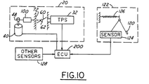
- Figures 4-10 illustrate various components of the assembly and the operation thereof.
- Figure 1 illustrates the assembly 20 in its assembled form (with the cover removed for clarity)
- Figure 2 illustrates the components of the assembly in an exploded condition
- Figure 3 is a cross-sectional view of the assembly 20 as shown in Figure 1.
- the electronic throttle control assembly 20 includes a housing or body member 22 and a cover member 24.
- the housing 22 includes a motor section 26, a throttle valve section 28, and a gear train section 30.
- the cover member 24 includes the throttle position sensor (TPS) 32, together with related electronics, which reads or "senses" the position of the throttle valve and transmits it to the electronic control unit (ECU) 200 of the vehicle (see Figure 11).
- TPS throttle position sensor
- ECU electronic control unit
- an electrical connector member 25 is positioned on the cover member 24.
- the connector member preferably has six contacts 27: two to the motor 40 which regulates the position of the throttle valve; and four to the TPS and related electronics.
- the electronic control unit sends a signal to the motor 40 which in turn operates the gear train 100 and adjusts the position of the throttle valve 60.
- the throttle valve is positioned in the main air passageway 72 from the air intake inside the engine compartment to the internal combustion engine. The precise position of the throttle valve in the airflow passageway is sensed by the TPS and relayed or fed back to the ECU in order to confirm or adjust the desired throttle valve setting.
- the throttle valve thus regulates the airflow to the internal combustion engine and in turn the speed of the engine and velocity of the vehicle.
- the cover member can be attached to the body member 22 in any conventional manner, but preferably is connected by a plurality of fastener members, such as screws or bolts 31.
- a series of openings 120 are provided in the cover member for mating with a series of sockets 122 on the gear section 30 of the housing 22.
- the sockets 122 can be threaded in order to securely hold the cover in place or threaded nuts could be utilized.
- an appropriate gasket or sealing member 124 is preferably positioned between the cover member and the housing in order to protect the gear train and TPS from dirt, moisture and other environmental conditions (see Figure 3).
- the electronic throttle control assembly 20 When the electronic throttle control assembly 20 is utilized, it is positioned in the engine compartment of the vehicle and bolted or otherwise securely fastened to the vehicle.
- a plurality of holes 21 are provided in the housing.
- the motor 40 is preferably a reversible thirteen volt DC motor although other conventional motors can be utilized.
- the motor 40 is connected to a mounting plate 42 which is bolted or otherwise securely fastened to the body member 22 by a plurality of bolts, screws, or other fasteners 44.
- the plate 42 also has a pair of contacts 43, as shown in Figure 2, which electrically connect the electronics in the cover member 24 to the motor 40.
- the motor 40 has a shaft 46 on which a small spur gear 48 is positioned.
- the gear 48 has a plurality of teeth 47 which mesh with and rotate adjacent gears, as described below.
- the throttle valve or plate 60 is secured to a throttle body shaft 62 which in turn is positioned in the throttle section 28 of the body member or housing 22.
- the throttle plate 60 is secured to the throttle body shaft 62 by a plurality of small fasteners or plate screws 64.
- the throttle shaft 62 is positioned in a bore or channel 70 in the throttle section of the body member 22.
- the bore 70 is transverse to the axis of the air flow passageway 72.
- Throttle shaft 62 has an O-ring channel or groove 74, a pair of flats or recesses 76 at the upper end for connection to one of the gears (as explained below), a pair of openings 78 for positioning of the plate screws therethrough, an axial or longitudinally extending slot 80 for positioning of the throttle plate 60 therein, and a pair of flats or recesses 82 at the lower end for use in assembling and positioning the throttle valve.
- the flats 82 are utilized to rotate the throttle shaft 62 during assembly of the throttle plate and also for orientation of the sector gear during the moulding or attachment process.
- An O-ring 84 is positioned in the channel 74 on the throttle shaft.
- the O-ring 84 provides a seal between the air in the air flow passageway 72 and the gear train components and electronics in the cover.
- a pair of bearings 86 and 88 are provided to allow the throttle body shaft to rotate freely in the housing.
- the bearings 86 and 88 are conventional ball-bearing members with pairs of races separated by small balls.
- an axial retainer clip member 90 preferably made of a spring steel material, is secured to the lower end of the shaft.
- the retainer clip member 90 holds the throttle body shaft 62 securely in position in the throttle section 28 of the body or housing member 22 and minimizes axial or longitudinal movement (or "play") of the shaft 62 in the housing.
- the clip member 90 is pushed or forced onto the shaft 62 until it contacts the inner race of bearing 88.
- the throttle body shaft being stepped in diameter, is then fixed axially to the inner race of the bearing.
- a spring clip member could also be utilized in order to pre-load the bearings to minimize radial movement of the shaft and also minimize axial movement of the shaft in the assembly 22.
- an end cap member or plug member 92 is positioned enclosing the cavity 94. This protects the lower end of the shaft from moisture, dirt and other environmental conditions which might adversely affect the operation of the throttle valve. This step is typically the last step in the assembly process since the end of the shaft 62 is left exposed until after all end-of-the-line testing has been completed.
- the gear assembly or gear train mechanism used with the electronic control assembly 20 in accordance with the present invention is generally referred to by the reference numeral 100.
- the gear train mechanism 100 includes spur gear 48 attached to motor 40, an intermediate gear member 102 (Figure 4), and a sector gear member 104 ( Figure 5).
- the intermediate gear member 102 is mounted on a shaft member 106 which is secured to the housing or body member 22 (see Figures 1-3).
- the intermediate gear member 102 rotates freely on shaft 106.
- the intermediate gear member 102 has a first series of gear teeth 108 on a first portion 109 and a second series of gear teeth 110 on a second portion 111.
- the gear teeth 108 on gear 102 are positioned to mesh with the gear teeth 47 on the motor driven gear 48, while the gear teeth 110 are positioned and adapted for mating with the gear teeth 112 on the sector gear 104.
- the teeth 112 on gear 104 are only provided on a portion or sector of the outside circumference of the gear member.
- All of the gear members 48, 102 and 104 are preferably made of a plastic material, such as nylon, although they can be made of any other comparable material, or metal, which has equivalent durability and function.
- the sector gear 104 is preferably moulded onto the end 63 of the throttle body shaft 62.
- recesses 76 are provided on the shaft 62 to allow the sector gear to be integrally moulded to the shaft and be permanently affixed thereto.
- the lower end 105 of the sector gear could also be extended in order to contact the inner race of bearing 86, thus helping to hold the throttle body shaft axially in position.
- the sector gear 104 has a central portion or member 114 which extends above the gear train 100 for communication with the throttle position sensor (TPS) mechanism 32 in the cover member 24.
- TPS throttle position sensor
- the TPS In order for the TPS to read the position of the throttle valve plate 60, the TPS must be able to correctly sense or read the movement and rotation of the throttle body shaft 62.
- two opposing flats are positioned on the upper end of the central member 114.
- the hub of the TPS is press-fit onto these flats and thus the position of the throttle shaft can be read accurately without relative movement between the TPS and the shaft.
- a socket member 118 could be provided on the cover member 24 in order to fit over the upper end of the central portion 114 of the sector gear (see Figure 3).
- the socket member 118 comes in close proximity to the default lever, limiting its axial movement.
- the force applied to the accelerator pedal 120 by the operator of the vehicle 122 is read by a sensor 124 and conveyed to the ECU 200 (see Figure 10).
- the accelerator pedal 120 is typically biased by a spring-type biasing member 126 in order to provide tactile feedback to the operator.
- the ECU of the vehicle also receives input from a plurality of other sensors 128 connected in other mechanisms and systems in the vehicle.
- a signal from the ECU 200 is sent to the motor 40.
- the motor rotates the spur gear 48 which then operates the gear train mechanism 100. More specifically, the gear member 48 rotates the intermediate gear member 102, which in turn rotates the sector gear member 104. This in turn causes the throttle body shaft 62, which is fixedly attached to the gear member 104, to rotate. Rotation of shaft 62 accurately positions the valve plate 62 in the passageway 72 and allows the requisite and necessary air flow into the engine in response to movement of the accelerator pedal 120.
- the present invention also has a failsafe (also known as "limp-home”) mechanism which allows the throttle valve plate to remain partially open in the event of a failure of the electronics system in the throttle control mechanism or in the entire vehicle.
- a failsafe also known as "limp-home” mechanism which allows the throttle valve plate to remain partially open in the event of a failure of the electronics system in the throttle control mechanism or in the entire vehicle.
- a main spring member 130, a default lever member 132 and a default spring member 134 are provided and utilized in combination with the sector gear member 104. These members act together to limit and control the operation of the valve plate member 60.
- the main spring member 130 is preferably a helical torsion spring member and is positioned in recess or pocket 152 in the housing 22 (see Figures 2-3).
- the main spring member 130 is positioned around the valve shaft member 62 as shown and acts to bias the sector gear 104 (and thus the valve or throttle plate member 60) relative to the housing 22.
- one end 154 of the main spring member 130 is fixedly positioned in slot 156 in the housing and the other end 158 of the spring member is bent and positioned in or around tab member 160 in the bottom of sector gear 104 (see Figure 3).
- the main spring member 130 biases the valve plate member 60 towards its closed position.
- the main spring member 130 is biased to return the valve or throttle plate member 60 > to or towards the closed position.
- the throttle plate 60 is positioned approximately parallel with the axis of the passageway 72 thus allowing a full compliment of air to pass into the engine.
- the default lever 132 and sector gear 104 are generally situated at the positions shown in Figure 7.
- the failsafe mechanism will automatically act to close the throttle valve in order to reduce the speed of the engine and the velocity of the vehicle.
- the default lever member 132 has an extending arm member 133.
- the default lever member 132 is positioned loosely over the upper end of the central portion 114 of the sector gear member 104 and has a first collar or circular flange member 137 which fits over the central portion 114.
- the default spring member 134 is positioned between the sector gear member 104 and the default spring member 132. In this regard, one end 140 of the default spring member 132 is connected to the sector gear member, while the other end 142 is connected to the default lever member 132.
- the default lever member 132 and extending arm member 133 prevent the throttle valve from closing completely.
- the default lever member acts to position the throttle valve in a slightly open position, thus allowing the vehicle to operate at a reduced speed and "limp-home."
- the housing 30 has a stop shoulder 144 thereon.
- a screw or threaded fastener member 146 can be used in cooperation with the stop shoulder in order to allow the actual stop position to be adjusted.
- the default lever is positioned in the housing such that the arm member 133 contacts the screw stop member 146 before the throttle plate reaches the fully closed position.
- the force or bias of the default spring member 134 is stronger or greater than the force or bias of the helical torsion main spring member 130, and thus the arm member and default lever member stops and prevents the sector gear from rotating any further.
- the positions of the sector gear and default lever members at this point of operation are shown in Figure 8.
- the resultant default or "limp-home" position of the throttle plate member 60 is shown in Figure 8A. When the valve or throttle plate member is in the default position, it is opened about 5°-10° from the throttle valve's closed position.
- the throttle plate In many engines known today, the throttle plate is manufactured and assembled to have a slight inclination on the order of 7°-10° in the fully closed position. This is to assure proper functioning of the valve plate in all conditions and prevent it from sticking or binding in the closed position. Thus, in the default or "limp-home" position, the throttle plate will be about 12°-20° from a position transverse to the axis of the air flow passageway.
- the motor 40 In order to overcome the force of the default spring member 134 and allow the throttle plate member 60 to be moved to its fully closed position, the motor 40 is operated.
- the motor through the gear train mechanism 100 turns or rotates the sector gear which in turn rotates the throttle shaft and closes the valve plate member 60.
- the motor forces the sector gear stop shoulder 164 against the screw stop member 146 in the housing.
- the position of the sector gear 104 and default lever member 132 at this point in operation is shown in Figure 9.
- the corresponding fully closed position of the throttle plate member 60 is shown in Figure 9A.
- the failsafe mechanism will automatically act to open the throttle plate to the default or "limp-home" position.
- the force of the default spring biasing member 134 will return the sector gear member 104 to the position shown in Figure 8 thus forcing the throttle shaft member 62 to rotate slightly and open the throttle valve 60.
- the throttle plate 60 In the failsafe position of operation, the throttle plate 60 is at a slightly opened position, as shown in Figure 8A. In such a position, the throttle valve allows some air to flow through the passageway 72, thus allowing the engine sufficient inlet air in order to operate the engine and for the vehicle to "limp-home".
- the throttle shaft member 62 (and thus the throttle valve plate member 60) is biased in all directions of operation of the throttle control valve system toward the default or limp-home position.
- the position of the screw stop member 146 in the housing can be adjusted (by the mating threaded relationship) in order to change or adjust the default position of the throttle plate member as desired.
- the screw stop member 170 or housing stop shoulder in combination with the stop shoulder 164 on the sector gear member 104 prevents further movement of the throttle plate past the fully closed position. This prevents sticking, binding, or "jamming" of the throttle valve plate member in the air passageway.
- the sector gear 104 and default lever member 132 also have corresponding ramp members 180 and 181 which mate with each other when the throttle valve assembly 20 is assembled. These are shown in Figures 2, 5, and 6A.
- the opposing ramp members keep the sector gear and default lever member from turning too far apart.
- the ramp members 180 and 181 also are used to keep the sector gear, default spring member and default lever member together as a subassembly module in order to aid in the assembly of the electronic throttle mechanism.
Landscapes
- Engineering & Computer Science (AREA)
- Chemical & Material Sciences (AREA)
- Combustion & Propulsion (AREA)
- Mechanical Engineering (AREA)
- General Engineering & Computer Science (AREA)
- Control Of Throttle Valves Provided In The Intake System Or In The Exhaust System (AREA)
Abstract
Description
Claims (10)
- A valve assembly comprising:wherein in the event of non-operation of said motor member, said main spring member and default lever mechanism act to position said shaft member in said third position.a housing;a fluid passageway in said housing;a shaft member rotatably positioned in said housing and extending through said fluid passageway;a valve member positioned in said fluid passageway, said valve member attached to said shaft member and rotatable therewith;a gear mechanism for rotating said shaft member between a first position in which said valve member is oriented to allow full passage of fluid in said passageway, and a second position in which said valve member is oriented to prevent fluid passage in said passageway;a motor member operably connected to said gear mechanism for causing said gear mechanism to rotate said shaft member;a main spring member for biasing said gear mechanism and shaft member in a direction away from said first position and toward said second position; anda spring-biased default lever mechanism for biasing said gear mechanism and shaft member in a direction away from said second position and to a third default position between said first and second positions;
- The valve assembly of claim 1 further comprising electronic means for operating said motor member.
- The valve assembly of claim 2 further comprising a cover member on said housing, at least a portion of said electronic means being positioned in said cover member.
- The valve assembly of claim 1 wherein said gear mechanism comprises at least a first gear member connected to said motor and a second gear member attached to said shaft member.
- The valve assembly of claim 4 further comprising a third gear member positioned between said first and second gear members.
- The valve assembly of claim 4 wherein said main spring member is biased between said second gear member and said housing.
- The valve assembly of claim 6 wherein said main spring member is a helical torsion spring member.
- The valve assembly of claim 1 wherein said default lever mechanism is biased by a default spring member biasingly positioned between said second gear member and said default lever mechanism.
- The valve assembly of claim 4 further comprising a stop member on said second gear member, said stop member positioned to limit rotation of said gear mechanism and thus said shaft member.
- An electronic throttle control assembly comprising:wherein operation of said motor rotates said throttle plate between said first position and said second position;a housing;an air passageway in said housing;a throttle shaft member rotatably positioned in said housing and extending through said air passageway;a throttle plate member attached to said throttle body shaft and positioned in said air passageway;said throttle plate member rotatably between a first position preventing air from passing through said air passageway and a second position allowing a full compliment of air to pass through said air passageway;a motor positioned in said housing having a rotatable motor shaft;a gear assembly positioned in said housing, said gear assembly comprising at least a first gear member attached to said motor shaft and a second gear member attached to said throttle shaft member;wherein in the event of failure of said motor, said throttle plate will be rotated to said third position and allow limited passage of air through said air passageway.a first spring member positioned between said housing and said second gear member, said first spring member biasing said throttle shaft member away from said second position and toward said first position;default mechanism positioned in said housing, said default mechanism comprising a default lever and default spring member;said default mechanism biasing rotation of said throttle body shaft toward a third position of said throttle plate between said first and second positions;
Applications Claiming Priority (2)
| Application Number | Priority Date | Filing Date | Title |
|---|---|---|---|
| US438162 | 1999-11-11 | ||
| US09/438,162 US6286481B1 (en) | 1999-11-11 | 1999-11-11 | Electronic throttle return mechanism with a two-spring and one lever default mechanism |
Publications (3)
| Publication Number | Publication Date |
|---|---|
| EP1099840A2 true EP1099840A2 (en) | 2001-05-16 |
| EP1099840A3 EP1099840A3 (en) | 2002-04-10 |
| EP1099840B1 EP1099840B1 (en) | 2003-07-16 |
Family
ID=23739507
Family Applications (1)
| Application Number | Title | Priority Date | Filing Date |
|---|---|---|---|
| EP00309730A Expired - Lifetime EP1099840B1 (en) | 1999-11-11 | 2000-11-03 | Electronic throttle return mechanism with a two-spring and one lever default mechanism |
Country Status (3)
| Country | Link |
|---|---|
| US (1) | US6286481B1 (en) |
| EP (1) | EP1099840B1 (en) |
| DE (1) | DE60003881T2 (en) |
Cited By (7)
| Publication number | Priority date | Publication date | Assignee | Title |
|---|---|---|---|---|
| GB2375584A (en) * | 2001-03-09 | 2002-11-20 | Visteon Global Tech Inc | A torsion spring assembly for a throttle |
| WO2003060305A1 (en) * | 2002-01-16 | 2003-07-24 | Siemens Aktiengesellschaft | Actuator |
| EP1375869A3 (en) * | 2002-06-27 | 2004-01-07 | Denso Corporation | Throttle device |
| EP1408218A1 (en) * | 2002-10-09 | 2004-04-14 | Aisan Kogyo Kabushiki Kaisha | Throttle control device |
| WO2004111425A1 (en) * | 2003-06-18 | 2004-12-23 | Siemens Aktiengesellschaft | Actuator for reversibly displacing a valve flap of a valve |
| EP2037101A1 (en) * | 2007-09-13 | 2009-03-18 | Magneti Marelli Powertrain S.p.A. | Throttle valve for an internal combustion engine |
| EP3173604A1 (en) * | 2015-11-25 | 2017-05-31 | Continental Automotive Systems, Inc. | Electronic throttle control assembly with default airflow adjustment pin |
Families Citing this family (16)
| Publication number | Priority date | Publication date | Assignee | Title |
|---|---|---|---|---|
| JP3945568B2 (en) * | 2000-12-27 | 2007-07-18 | 株式会社デンソー | Intake control device for internal combustion engine |
| DE10205090A1 (en) * | 2002-02-07 | 2003-09-04 | Bosch Gmbh Robert | Throttle body with modular cover element |
| ITBO20030532A1 (en) * | 2003-09-15 | 2005-03-16 | Magneti Marelli Powertrain Spa | METHOD FOR THE REALIZATION OF A BUTTERFLY VALVE A |
| ITBO20030531A1 (en) * | 2003-09-15 | 2005-03-16 | Magneti Marelli Powertrain Spa | BUTTERFLY VALVE ELECTRONICALLY CONTROLLED |
| ITBO20030530A1 (en) * | 2003-09-15 | 2005-03-16 | Magneti Marelli Powertrain Spa | BUTTERFLY VALVE SERVO ASSISTED WITH A FLEXIBLE SPRING AND A SPIRAL SPRING TO ESTABLISH LIMP-HOME POSITION |
| JP4366324B2 (en) * | 2005-03-17 | 2009-11-18 | 三菱電機株式会社 | Intake air amount control device for internal combustion engine |
| US7388156B2 (en) * | 2005-12-15 | 2008-06-17 | Teleflex Automotive Germany Gmbh | Gasket for a cable control line in an engine compartment |
| JP2008240610A (en) * | 2007-03-27 | 2008-10-09 | Aisan Ind Co Ltd | Throttle device of internal combustion engine |
| JP4760763B2 (en) * | 2007-04-23 | 2011-08-31 | スズキ株式会社 | Electronically controlled throttle valve device |
| US7490590B1 (en) * | 2008-03-27 | 2009-02-17 | Ford Global Technologies, Llc | Electronic throttle |
| US8201542B2 (en) * | 2009-08-17 | 2012-06-19 | Aeon Motor Co., Ltd. | Safety device for the throttle operation |
| JP5357105B2 (en) * | 2010-05-19 | 2013-12-04 | 株式会社デンソー | Throttle device |
| FR2984960B1 (en) * | 2011-12-21 | 2013-12-20 | Valeo Sys Controle Moteur Sas | DOSER TWO WAYS WITH DOSAGE ON EACH TRACK |
| US10054062B1 (en) | 2014-12-15 | 2018-08-21 | Brunswick Corporation | Systems and methods for controlling an electronic throttle valve |
| US10125696B2 (en) * | 2015-04-14 | 2018-11-13 | Walbro Llc | Charge forming device with throttle valve adjuster |
| US10138821B1 (en) | 2017-08-31 | 2018-11-27 | GM Global Technology Operations LLC | Method of making a throttle body |
Family Cites Families (51)
| Publication number | Priority date | Publication date | Assignee | Title |
|---|---|---|---|---|
| US2924424A (en) | 1955-11-17 | 1960-02-09 | Gen Electric | Temperature compensated butterfly valve |
| DE1239533B (en) | 1962-03-09 | 1967-04-27 | Klein Schanzlin & Becker Ag | Sealing of the actuation shaft of valves with a flap-shaped valve body |
| US4008877A (en) | 1972-11-30 | 1977-02-22 | Kubota, Ltd. | Butterfly valve apparatus |
| US3924596A (en) | 1973-01-12 | 1975-12-09 | Volkswagenwerk Ag | Fail-safe throttle for an internal combustion engine |
| JPS60190626A (en) | 1984-03-09 | 1985-09-28 | Hitachi Ltd | Throttle valve controlling device |
| DE3631283C2 (en) | 1986-09-13 | 1999-11-25 | Bosch Gmbh Robert | Device for the controlled metering of combustion air in an internal combustion engine |
| US4838226A (en) | 1986-12-12 | 1989-06-13 | Nippondenso Co., Ltd. | Apparatus for controlling intake air flow rate in internal combustion engine |
| JPS63113738U (en) | 1987-01-19 | 1988-07-22 | ||
| JPH086611B2 (en) | 1987-03-26 | 1996-01-29 | 日産自動車株式会社 | In-vehicle engine control device |
| JPS6424129A (en) | 1987-07-20 | 1989-01-26 | Hitachi Ltd | Throttle valve opening and closing mechanism |
| EP0300479B1 (en) | 1987-07-22 | 1992-05-06 | Mitsubishi Denki Kabushiki Kaisha | Throttle valve controlling apparatus |
| US4827884A (en) | 1987-10-02 | 1989-05-09 | Bendix Electronics Limited | Throttle assembly |
| DE3743309A1 (en) | 1987-12-21 | 1989-06-29 | Bosch Gmbh Robert | METHOD AND DEVICE FOR DETECTING AND RELAXING CLAMPED CONTROL ELEMENTS |
| DE3813047A1 (en) | 1988-04-19 | 1989-11-02 | Pierburg Gmbh | ADJUSTING DEVICE FOR THE THROTTLE VALVE OF A MIXING FORMING DEVICE FOR INTERNAL COMBUSTION ENGINES |
| JPH0646010B2 (en) | 1988-07-14 | 1994-06-15 | 本田技研工業株式会社 | Throttle control device |
| US4873954A (en) | 1988-07-27 | 1989-10-17 | Colt Industries Inc. | Fail-safe idle bypass system |
| JP2881776B2 (en) | 1988-08-31 | 1999-04-12 | アイシン精機株式会社 | Throttle control device |
| JPH0270932A (en) | 1988-09-03 | 1990-03-09 | Aisin Seiki Co Ltd | Throttle control device |
| EP0389649B1 (en) | 1989-03-25 | 1994-05-11 | Audi Ag | Throttle valve |
| US4991552A (en) | 1989-04-03 | 1991-02-12 | Vdo Adolf Schindling Ag | Throttle valve setting device |
| DE3918853A1 (en) | 1989-06-09 | 1990-12-13 | Pierburg Gmbh | ELECTRICALLY CONTROLLED THROTTLE OPERATING DEVICE FOR INTERNAL COMBUSTION ENGINES |
| DE3927043A1 (en) | 1989-08-16 | 1991-02-21 | Vdo Schindling | LOAD ADJUSTMENT DEVICE |
| DE3927004A1 (en) | 1989-08-16 | 1991-02-21 | Vdo Schindling | LOAD ADJUSTMENT DEVICE |
| JPH0385337A (en) | 1989-08-29 | 1991-04-10 | Mitsubishi Electric Corp | Throttle valve control device for engine |
| DE4006419C2 (en) | 1990-03-01 | 1998-12-24 | Bosch Gmbh Robert | Device with an actuator |
| US5168951A (en) | 1990-03-16 | 1992-12-08 | Aisan Kogyo Kabushiki Kaisha | Throttle valve operating device with traction control function |
| DE4011182A1 (en) | 1990-04-06 | 1991-10-10 | Audi Ag | THROTTLE |
| US5161508A (en) | 1990-05-07 | 1992-11-10 | Vdo Adolf Schindling Ag | Load adjustment device |
| CA2044213A1 (en) | 1990-07-12 | 1992-01-13 | Paul L. Gluchowski | Valve assembly |
| DE4034575A1 (en) | 1990-10-31 | 1992-05-07 | Vdo Schindling | LOAD ADJUSTMENT DEVICE |
| JPH0684728B2 (en) | 1990-11-29 | 1994-10-26 | 三菱電機株式会社 | Throttle valve opening / closing device for internal combustion engine |
| DE4039937A1 (en) | 1990-12-14 | 1992-06-17 | Audi Ag | IDLE FILLING REGULATOR |
| JP3205002B2 (en) | 1991-05-20 | 2001-09-04 | 株式会社日立製作所 | Throttle actuator |
| DE4141104C2 (en) | 1991-12-13 | 1995-09-07 | Vdo Schindling | Device for adjusting a throttle valve |
| DE4243893C2 (en) | 1991-12-26 | 1996-03-28 | Hitachi Ltd | Device for controlling a throttle valve of an internal combustion engine |
| JP2784867B2 (en) | 1992-01-08 | 1998-08-06 | 株式会社ユニシアジェックス | Control valve control device |
| DE4206523A1 (en) | 1992-03-02 | 1993-09-09 | Vdo Schindling | DEVICE FOR ADJUSTING A THROTTLE VALVE |
| DE4214179C1 (en) | 1992-04-30 | 1993-05-06 | Mercedes-Benz Aktiengesellschaft, 7000 Stuttgart, De | |
| FR2692622B1 (en) | 1992-06-17 | 1994-09-16 | Solex | Rotary throttle member for internal combustion engine power supply installation and throttle body including application. |
| DE4337184A1 (en) | 1993-10-30 | 1995-05-04 | Pierburg Gmbh | Throttle body |
| US5429090A (en) | 1994-02-28 | 1995-07-04 | Coltec Industries Inc. | Fail safe throttle positioning system |
| EP0714478B1 (en) | 1994-06-18 | 2000-04-26 | AB Elektronik GmbH | Throttle valve device |
| US5492097A (en) | 1994-09-30 | 1996-02-20 | General Motors Corporation | Throttle body default actuation |
| DE69627401T3 (en) * | 1995-01-17 | 2014-01-30 | Hitachi, Ltd. | Airflow control device |
| DE19524941B4 (en) | 1995-07-08 | 2006-05-18 | Siemens Ag | load adjusting |
| US5630571A (en) | 1995-10-16 | 1997-05-20 | General Motors Corporation | Exhaust flow control valve |
| DE19612869A1 (en) * | 1996-03-30 | 1997-10-02 | Bosch Gmbh Robert | Control device for controlling a power of an engine |
| JPH102236A (en) * | 1996-06-17 | 1998-01-06 | Aisan Ind Co Ltd | Controller for throttle valve |
| EP0828067B1 (en) * | 1996-09-03 | 2005-01-12 | Hitachi, Ltd. | A throttle valve control device for an internal combustion engine |
| AUPO271696A0 (en) * | 1996-10-02 | 1996-10-24 | Orix Vehicle Technology Pty Ltd | Engine manifold valve control |
| US6070852A (en) * | 1999-01-29 | 2000-06-06 | Ford Motor Company | Electronic throttle control system |
-
1999
- 1999-11-11 US US09/438,162 patent/US6286481B1/en not_active Expired - Lifetime
-
2000
- 2000-11-03 DE DE60003881T patent/DE60003881T2/en not_active Expired - Fee Related
- 2000-11-03 EP EP00309730A patent/EP1099840B1/en not_active Expired - Lifetime
Cited By (17)
| Publication number | Priority date | Publication date | Assignee | Title |
|---|---|---|---|---|
| GB2375584A (en) * | 2001-03-09 | 2002-11-20 | Visteon Global Tech Inc | A torsion spring assembly for a throttle |
| GB2375584B (en) * | 2001-03-09 | 2003-05-21 | Visteon Global Tech Inc | Torsion spring assembly for electronic throttle |
| US6647960B2 (en) | 2001-03-09 | 2003-11-18 | Visteon Global Technologies, Inc. | Torsion spring assembly for electronic throttle |
| US6672280B2 (en) | 2001-03-09 | 2004-01-06 | Visteon Global Technologies, Inc. | Torsion spring assembly for electronic throttle |
| WO2003060305A1 (en) * | 2002-01-16 | 2003-07-24 | Siemens Aktiengesellschaft | Actuator |
| EP1375869A3 (en) * | 2002-06-27 | 2004-01-07 | Denso Corporation | Throttle device |
| US6966296B2 (en) | 2002-06-27 | 2005-11-22 | Denso Corporation | Throttle device |
| US6851410B2 (en) | 2002-10-09 | 2005-02-08 | Aisan Kogyo Kabushiki Kaisha | Throttle control device |
| EP1408218A1 (en) * | 2002-10-09 | 2004-04-14 | Aisan Kogyo Kabushiki Kaisha | Throttle control device |
| WO2004111425A1 (en) * | 2003-06-18 | 2004-12-23 | Siemens Aktiengesellschaft | Actuator for reversibly displacing a valve flap of a valve |
| US7032877B2 (en) | 2003-06-18 | 2006-04-25 | Siemens Ag | Actuator for reversibly displacing a valve flap of a valve |
| EP2037101A1 (en) * | 2007-09-13 | 2009-03-18 | Magneti Marelli Powertrain S.p.A. | Throttle valve for an internal combustion engine |
| EP3173604A1 (en) * | 2015-11-25 | 2017-05-31 | Continental Automotive Systems, Inc. | Electronic throttle control assembly with default airflow adjustment pin |
| JP2017101672A (en) * | 2015-11-25 | 2017-06-08 | コンチネンタル オートモーティブ システムズ インコーポレイテッドContinental Automotive Systems, Inc. | Electronic throttle control assembly with default air flow adjustment pin |
| CN107013343A (en) * | 2015-11-25 | 2017-08-04 | 大陆汽车系统公司 | Electronic Throttle Control component with acquiescence air stream adjusting pin |
| US10138820B2 (en) | 2015-11-25 | 2018-11-27 | Continental Automotive Systems, Inc. | Electronic throttle control assembly with default airflow adjustment pin |
| CN107013343B (en) * | 2015-11-25 | 2021-05-25 | 大陆汽车系统公司 | Electronic throttle control assembly with default airflow adjustment pins |
Also Published As
| Publication number | Publication date |
|---|---|
| DE60003881D1 (en) | 2003-08-21 |
| US6286481B1 (en) | 2001-09-11 |
| EP1099840A3 (en) | 2002-04-10 |
| DE60003881T2 (en) | 2004-05-27 |
| EP1099840B1 (en) | 2003-07-16 |
Similar Documents
| Publication | Publication Date | Title |
|---|---|---|
| US6267352B1 (en) | Electronic throttle return mechanism with default and gear backlash control | |
| US6173939B1 (en) | Electronic throttle control system with two-spring failsafe mechanism | |
| EP1099840B1 (en) | Electronic throttle return mechanism with a two-spring and one lever default mechanism | |
| US6070852A (en) | Electronic throttle control system | |
| US6095488A (en) | Electronic throttle control with adjustable default mechanism | |
| US6244565B1 (en) | Throttle body shaft axial play control | |
| EP1099842B1 (en) | Electronic throttle return mechanism with a two-spring and two-lever default mechanism | |
| US6155533A (en) | Default mechanism for electronic throttle control system | |
| EP1170484B1 (en) | Electronic throttle control mechanism with gear alignment and mesh maintenance system | |
| EP1170487B1 (en) | Electronic throttle control mechanism with reduced friction and wear | |
| US5687691A (en) | Throttle device and method for producing a throttle device | |
| US7013870B2 (en) | Throttle apparatus for an engine | |
| US6279535B1 (en) | Throttle control device | |
| US7337758B2 (en) | Charge motion control valve actuator | |
| EP1170486B1 (en) | Electronic throttle control mechanism with integrated modular construction | |
| CA2044213A1 (en) | Valve assembly | |
| US6622984B2 (en) | Electronic throttle body with low friction default mechanism | |
| US6874470B2 (en) | Powered default position for motorized throttle | |
| US6158417A (en) | Throttle body accomodation of either an idle air control valve or a motorized throttle control | |
| WO2006045027A2 (en) | Charge motion control valve actuator | |
| JPH0350347A (en) | Control valve device for automotive engine | |
| JP2003176731A (en) | Engine throttle | |
| JP2000505861A (en) | Throttle device for internal combustion engine | |
| JPH0350342A (en) | Control device for automotive engine |
Legal Events
| Date | Code | Title | Description |
|---|---|---|---|
| PUAI | Public reference made under article 153(3) epc to a published international application that has entered the european phase |
Free format text: ORIGINAL CODE: 0009012 |
|
| AK | Designated contracting states |
Kind code of ref document: A2 Designated state(s): AT BE CH CY DE DK ES FI FR GB GR IE IT LI LU MC NL PT SE TR Kind code of ref document: A2 Designated state(s): DE GB |
|
| AX | Request for extension of the european patent |
Free format text: AL;LT;LV;MK;RO;SI |
|
| PUAL | Search report despatched |
Free format text: ORIGINAL CODE: 0009013 |
|
| AK | Designated contracting states |
Kind code of ref document: A3 Designated state(s): AT BE CH CY DE DK ES FI FR GB GR IE IT LI LU MC NL PT SE TR |
|
| AX | Request for extension of the european patent |
Free format text: AL;LT;LV;MK;RO;SI |
|
| 17P | Request for examination filed |
Effective date: 20020426 |
|
| 17Q | First examination report despatched |
Effective date: 20020614 |
|
| GRAH | Despatch of communication of intention to grant a patent |
Free format text: ORIGINAL CODE: EPIDOS IGRA |
|
| AKX | Designation fees paid |
Free format text: DE GB |
|
| GRAH | Despatch of communication of intention to grant a patent |
Free format text: ORIGINAL CODE: EPIDOS IGRA |
|
| GRAA | (expected) grant |
Free format text: ORIGINAL CODE: 0009210 |
|
| AK | Designated contracting states |
Designated state(s): DE GB |
|
| REG | Reference to a national code |
Ref country code: GB Ref legal event code: FG4D |
|
| REG | Reference to a national code |
Ref country code: IE Ref legal event code: FG4D |
|
| REF | Corresponds to: |
Ref document number: 60003881 Country of ref document: DE Date of ref document: 20030821 Kind code of ref document: P |
|
| PLBE | No opposition filed within time limit |
Free format text: ORIGINAL CODE: 0009261 |
|
| STAA | Information on the status of an ep patent application or granted ep patent |
Free format text: STATUS: NO OPPOSITION FILED WITHIN TIME LIMIT |
|
| 26N | No opposition filed |
Effective date: 20040419 |
|
| REG | Reference to a national code |
Ref country code: IE Ref legal event code: MM4A |
|
| REG | Reference to a national code |
Ref country code: GB Ref legal event code: 732E |
|
| PGFP | Annual fee paid to national office [announced via postgrant information from national office to epo] |
Ref country code: DE Payment date: 20081128 Year of fee payment: 9 |
|
| PGFP | Annual fee paid to national office [announced via postgrant information from national office to epo] |
Ref country code: GB Payment date: 20081008 Year of fee payment: 9 |
|
| GBPC | Gb: european patent ceased through non-payment of renewal fee |
Effective date: 20091103 |
|
| PG25 | Lapsed in a contracting state [announced via postgrant information from national office to epo] |
Ref country code: DE Free format text: LAPSE BECAUSE OF NON-PAYMENT OF DUE FEES Effective date: 20100601 |
|
| PG25 | Lapsed in a contracting state [announced via postgrant information from national office to epo] |
Ref country code: GB Free format text: LAPSE BECAUSE OF NON-PAYMENT OF DUE FEES Effective date: 20091103 |