EP1099608A2 - Water-drop proof structure for wiper motor apparatus - Google Patents
Water-drop proof structure for wiper motor apparatus Download PDFInfo
- Publication number
- EP1099608A2 EP1099608A2 EP00309910A EP00309910A EP1099608A2 EP 1099608 A2 EP1099608 A2 EP 1099608A2 EP 00309910 A EP00309910 A EP 00309910A EP 00309910 A EP00309910 A EP 00309910A EP 1099608 A2 EP1099608 A2 EP 1099608A2
- Authority
- EP
- European Patent Office
- Prior art keywords
- output shaft
- wiper motor
- cover
- connector
- accommodation casing
- Prior art date
- Legal status (The legal status is an assumption and is not a legal conclusion. Google has not performed a legal analysis and makes no representation as to the accuracy of the status listed.)
- Granted
Links
Images


Classifications
-
- B—PERFORMING OPERATIONS; TRANSPORTING
- B60—VEHICLES IN GENERAL
- B60S—SERVICING, CLEANING, REPAIRING, SUPPORTING, LIFTING, OR MANOEUVRING OF VEHICLES, NOT OTHERWISE PROVIDED FOR
- B60S1/00—Cleaning of vehicles
- B60S1/02—Cleaning windscreens, windows or optical devices
- B60S1/04—Wipers or the like, e.g. scrapers
- B60S1/06—Wipers or the like, e.g. scrapers characterised by the drive
- B60S1/16—Means for transmitting drive
- B60S1/166—Means for transmitting drive characterised by the combination of a motor-reduction unit and a mechanism for converting rotary into oscillatory movement
-
- B—PERFORMING OPERATIONS; TRANSPORTING
- B60—VEHICLES IN GENERAL
- B60S—SERVICING, CLEANING, REPAIRING, SUPPORTING, LIFTING, OR MANOEUVRING OF VEHICLES, NOT OTHERWISE PROVIDED FOR
- B60S1/00—Cleaning of vehicles
- B60S1/02—Cleaning windscreens, windows or optical devices
- B60S1/04—Wipers or the like, e.g. scrapers
- B60S1/06—Wipers or the like, e.g. scrapers characterised by the drive
- B60S1/08—Wipers or the like, e.g. scrapers characterised by the drive electrically driven
Definitions
- the present invention relates to a wiper motor device which are used in vehicles such as automobiles and trucks, etc.
- an output shaft which is the pivot axis of the wiper, that outputs motive power via a reduction mechanism and a link mechanism, is disposed at a position adjacent to a drive circuit portion.
- the drive circuit portion incorporates circuits which control execution of various types of wiping actions such as intermittent wiping, etc. and is disposed inside a body sheet material (glass plate and body outer plate, etc.,).
- the tip end portion of the output shaft extends through an attaching hole formed in the body plate material so that it protrudes outside the body, and a wiper arm is connected to the protruding tip end portion of the shaft.
- the drive circuit portion is located in an accommodation casing which is closed by a cover in order to prevent foreign substances from adhering to the drive circuit portion.
- the cover is fixed to the accommodation casing by means of engagement claws projecting from the accommodation casing locating in holes opened in the cover.
- a waterproof member such as a grommet, has been attached to the attaching through holes of the output shaft, thereby acting as a seal to prevent water from seeping into the body interior.
- a drip-proof structure for a wiper motor device in which a drive circuit portion of a wiper motor is disposed adjacent to an output shaft of the wiper motor, wherein when providing a cover to shield an upper opening of an accommodation casing for accommodating said drive circuit portion, an extension portion fitted to the outer circumference of the abovementioned output shaft in a drip-proof state is formed on said cover and is caused to extend therefrom.
- a cylindrical portion fitted to the outer circumference of the output shaft is formed at the extension portion of the cover, by fitting the base end of the waterproof cap attached to the output shaft to the outer circumference of the tip end side of the corresponding cylindrical portion, it is possible to fit the extension portion to the output shaft in a drip-proof state.
- a guide rib is formed at the upper surface portion of the cover, which guides so as to prevent water flowing on the upper surface of the cover from reaching the fixing portion to fix the accommodation casing and cover, it is possible to prevent water from invading the accommodation casing from the fixing portion. Therefore, a still excellent drip-proof structure can be obtained.
- a wiper motor device 1 is provided to wipe the rear window glass surface of a vehicle.
- the wiper motor device 1 is disposed inside the body plate material of the vehicle (glass plate and body plate (not illustrated).
- the device comprises a motor portion 2 provided with an electric motor (not illustrated), gear portion 4 including a reduction mechanism (not illustrated), a link mechanism (not illustrated), an output shaft (which is the pivot axis of the wiper) 3, and a drive circuit portion 6 provided with a circuit board 5. etc.
- the electric motor is driven and controlled by circuits incorporated in the circuit board 5, and the motive power of the motor is transmitted from the output shaft 3 via the reduction mechanism and the link mechanism.
- This basic construction is the same as that of conventional devices.
- a gear frame 7 accommodates the abovementioned gear portion 4.
- the output shaft 3 is rotatably supported in a sleeve 8 formed integrally with the gear frame 7, and the tip end of the output shaft 3, which protrudes from the sleeve 8, extends through an attaching hole (not illustrated) formed in the body plate material so that it protrudes outside the body (that is, outside the body plate material).
- the base end portion of a wiper arm (not illustrated) is connected to the protruding tip end portion of the shaft 3.
- a grommet (not illustrated) is attached to the attaching hole through which the output shaft 3, extends and acts as a seal to prevent water from seeping into the through hole and into the body interior.
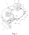
- the wiper motor device I is, as shown in FIG. 3, attached to the body side so that the tip end side of the output shaft 3 is extends obliquely upward when view in side elevational and the drive circuit portion 6 is located obliquely downwardly of the base end portion of the output shaft 3.
- the tip end side of the output shaft 3 will be referred to as "upward”
- the base end side will be referred to as "downward” in a situation where the wiper motor device I is not attached to the body side.
- the drive circuit portion 6 is accommodated in an accommodation casing 10, which is formed integrally with the gear frame 7, and wires (not illustrated) and a connector 9, etc., to which an electric motor is connected are attached to the circuit board 5.
- the upper side of the accommodation casing 10 is open, and the upper opening is closed by a cover 11.
- the cover 11 is formed to have a side portion 11b which depends downwardly from the outer circumferential edge of a plate-like upper surface portion 11a. Further, a plurality of tongues 11c are formed to depend downwardly from the lower edge of the side portion llb. Engagement holes 11d are provided to be open on the tongues lie. Engagement claws 10a corresponding to the engagement holes lid of the cover are provided on the upper portion of the accommodation casing so as to protrude therefrom. When the cover 11 is placed over the upper opening of the accommodation casing 10, the cover 11 is secured to the accommodation casing 10 by engaging the engagement claws 10a in the engagement holes lid.
- An extension portion lie is formed integrally with the upper surface portion 11a of the cover 11 and is located in a position in which it surrounds the outer circumference of the sleeve 8 that pivotally supports the output shaft 3.
- a cylindrical portion 11f locates closely around the outer circumference of the sleeve 8 and is integrally formed with the extension portion lie. The cylindrical portion 11f extends upwardly from the extension portion 11e. The upper end of the sleeve 8 protrudes from the upper end of the cylindrical portion 11f, and as described above, the output shaft 3 protrudes from the upper end of the sleeve 8.
- Reference numeral 12 indicates a waterproof cap.
- the waterproof cap 12 is generally cylindrical and has a diameter which increases stepwise downwardly (two steps in the present embodiment).
- the upper end portion of the cap 12 engages with a lower end portion of the protruding part of output shaft 3 and contacts the circumference of the shaft in a slightly pressure-fitted state.
- the lower portion of the waterproof cap 12 is located around the outer circumference of the upper part of the cylindrical portion 11f of the abovementioned cover 11, so that a labyrinth path is formed between the lower part of the waterproof cap 12 and the upper part of the cylindrical portion 11f.
- Guide ribs 11g are formed on the upper surface portion 11a of the cover 11 in a state where the wiper motor device 1 is attached at the body side.
- the guide ribs 11g can guide water flowing on the upper surface portion 11a so that the water does not flow into the engagement holes 11d.
- the guide ribs 11g are, as shown in FIG. 1, located inwardly of the engagement holes lid with respect to the output shaft 3.
- the configuration of the ribs is not limited to this arrangement.
- the guide ribs 11g may be arranged so as to surround the engagement holes 11d.
- the shape and/or position of the guide ribs 11g are not limited to any particular configuration.
- the accommodation casing 10 is disposed at the lower part of the main surface (hereinafter referred to the front elevation) at the side from which the output shaft 3 of the gear frame 7 protrudes, and is formed so as to define a rectangular opening which is similar in shape to the circuit board 5 but larger in size than the circuit board 5.
- An insertion hole 14 into which a connector 9 can be inserted is provided on the bottom wall of the accommodation casing 10 and a cut-away portion 15 is formed along three side walls of the insertion hole 14 of the accommodation casing 10.
- An external force receiving portion 16 that receives an external force applied to the connector 9 is formed on the rear of the cut-away portion 15.
- a twisting force receiving portion 17 that receives a twisting force applied to the connector 9 is formed at one side of the notched portion 15.
- a holder 18 for the wiper motor device 1 is made of resin and is, as shown in FIG. 8, integrally formed so as to be bifurcated like a fork in its front elevational view.
- the inner spacing of a pair of bifurcated insertion portions 19 and 20 is set to be almost equal to the outer diameter of the connector 9, wherein the pair of bifurcated insertion portions can be fitted onto the outer circumference of the connector 9.
- An engagement part 21 that looks roughly like an isosceles triangle in its front elevational view is formed to protrude inwardly at the tip end portion of the inside of one of the insertion portions (hereinafter referred to as a lower insertion portion).
- the engagement part 21 is arranged to engage with the lower corner of the coupler 9 when a holder 18 is fitted to the connector 9, whereby the holder 18 itself is prevented from disengaging therefrom.
- a fixing part 22 whose side elevational view is roughly rectangular is formed to extend at a right angle to both insertion portions 19 and 20 of the holder 18, and a bending part 23 is bent to form an intermediate portion of the fixing part 22 so that the tip end thereof can be moved in parallel to the direction of both insertion portions 19 and 20.
- the tip end portion of the fixing part 22 is set to be engaged with the cover 11 from the outside when the holder 18 is fitted to the connector 9.
- the bent part 23 is configured so that there is a gap between the inner circumferential side thereof and the outer wall of the accommodation casing 10, whereby it is possible to prevent it from interfering with the edge part of the external force receiving portion 16.
- the circuit board 5 When the connector 9 is accommodated in the accommodation casing 10, the circuit board 5 is positioned with respect to its forward, vertical and left and right directions since the front main surface (hereinafter referred to the front surface) is brought into contact with the bottom (rear surface) of the accommodation casing 10, and the outer circumference is brought into contact with the side wall internal surface of the four sides (hereinafter referred to the vertical and left and right sides) of the accommodation casing 10. Also, as shown in FIG. 10, the connector 9 protrudes from the notched portion of the gear frame 7, and the side (hereinafter referred to the left side) of a controller 24 is brought into contact with the twisting force receiving portion 17.
- the holder 18 closes the insertion hole 14 and assumes a state where it is engaged with a part of the rear surface of the connector 9. Therefore, the circuit board 5 is prevented by the holder 18 from coming off rearwardly.
- a wiper motor device 1 produced as described above is installed below the window of a vehicle, and when a mating coupler (not illustrated) wired at the vehicle side is connected to the connector 9, an insertion force generated by the mating coupler indicated by the arrow F in FIG. 11(A) is applied to the connector 9. If the insertion force F is applied to the circuit board 5, there is a risk that the circuit board 5 itself and the controller 24 (electric wires, electric components, and soldered parts) may be damaged, wherein the reliability of the circuit board 5 is reduced.
- the insertion force F of the mating coupler can be received by the external force receiving portion 16 of the gear frame 7 via the holder 18, wherein the insertion force F of the mating coupler can be prevented from being applied to the circuit board 5, and it is possible to prevent the circuit board 5 from being damaged by the insertion force of the mating coupler into the connector 9.
- the weight of the gear frame 7 can be further lightened in comparison with a type such as shown in dot-dash line in Fig. 11(A) in which a portion 10c surrounding the entire circumference of the connector 9 is formed at the insertion hole 14 of the coupler 9 of the accommodation casing 10 of the gear frame, and the connector 9 can be exposed at the cut-away portion 15. Therefore, the operation of coupling the mating coupler into the connector 9 can be facilitated.
- FIG. 13 A third embodiment is shown in FIG. 13.
- the circuit board 5A is inserted into the accommodation casing 10A, and the connector 9A extends at a right angle with respect to the axial direction of the output shaft 3.
- the connector 9A is fixed laterally of the circuit board 5A and is laterally inserted into the insertion hole 14A of the accommodation casing 10A from the rear.
- the circuit board 5A When the circuit board 5A is accommodated in the accommodation casing 10A, the circuit board 5A is positioned with respect to the forward and four sides (hereinafter called vertical and left and right directions) of the accommodation casing 10A since the front side main surface (hereinafter called the front side) is brought into contact with the bottom (rear side) of the accommodation casing 10A and the outer circumference is brought into contact with the four internal sides of the casing 10A. Thereafter, when the cover 11 is placed on the casing 10A, the cover 11 presses the circuit board 5A from the outside, wherein the circuit board 5A is completely prevented from coming out from the accommodation casing 10A. In this state.
- the gear frame 7 can directly receive such forces from the connector 9A because the flange portion 16A of the gear frame 7 is fitted in a retaining groove of the connector 9A. Therefore, such forces will not be applied to the circuit board 5A, and it is possible to prevent the circuit board 5A from being damaged by such forces.
- the wiper motor device 1 is attached to the body side in such a way that the drive circuit portion 6 is positioned downwardly of the output shaft 3.
- the extension portion lie is formed on the cover 11 to enclose the upper opening of the accommodation casing 10, in which the drive circuit portion 6 is accommodated, so as to extend to the sleeve 8 which pivotally supports the output shaft 3.
- the cylindrical portion 11f that is fitted to the outer circumference of the sleeve 8 is made to extend upwardly from the extension portion lie, and the lower end of the waterproof cap 12 pressure-fitted and attached to the output shaft 3 is externally fitted around the upper part of the cylindrical portion 11f.
- the cover 11 since the cover 11 is fixed to the accommodation casing 10, the cylindrical portion 11f will not move at all.
- the waterproof cap 12 is slightly pressure-fitted to the output shaft 3 and thus rotates along with the output shaft 3. Further, since a labyrinth path resulting from the edge of the cylindrical portion 11f overlapping that of the waterproof cap 12 is employed, no adverse influence is applied to the drive of an electric motor by using the waterproof cap 12, wherein it is possible to favorably provide a drip-proof effect.
- the present invention is not limited to the abovementioned embodiments.
- the upper end portion of the cover cylindrical portion 11f may he constructed as an integral structure in which it is fitted to the output shaft 3 protruding from the upper end of the sleeve 8 in a drip-proof state, wherein effects similar to the above can be achieved.
Abstract
Description
- The present invention relates to a wiper motor device which are used in vehicles such as automobiles and trucks, etc.
- There exists a type of a wiper motor device in which an output shaft, which is the pivot axis of the wiper, that outputs motive power via a reduction mechanism and a link mechanism, is disposed at a position adjacent to a drive circuit portion. The drive circuit portion (circuit board, etc.) incorporates circuits which control execution of various types of wiping actions such as intermittent wiping, etc. and is disposed inside a body sheet material (glass plate and body outer plate, etc.,). The tip end portion of the output shaft extends through an attaching hole formed in the body plate material so that it protrudes outside the body, and a wiper arm is connected to the protruding tip end portion of the shaft. In this type of device, the drive circuit portion is located in an accommodation casing which is closed by a cover in order to prevent foreign substances from adhering to the drive circuit portion. The cover is fixed to the accommodation casing by means of engagement claws projecting from the accommodation casing locating in holes opened in the cover.
- In such a wiper motor device, it is necessary to prevent water from seeping into the body interior through the attaching hole of the output shaft. Therefore, conventionally, a waterproof member, such as a grommet, has been attached to the attaching through holes of the output shaft, thereby acting as a seal to prevent water from seeping into the body interior.
- However, even when a waterproof member such as a grommet is attached, there are cases where water can seep into the body interior through a slight gap at the attaching through holes of the output shaft, for example during periods of heavy rain or washing the vehicle with high pressure water. Also, in the case where the drive circuit portion is disposed downwardly of the output shaft, there is a risk that water seeps into the body interior, flows into the drive circuit portion side and further invades the accommodation casing between the cover and accommodation casing or through the engagement holes. Therefore, if water or humidity that thus entered the accommodation casing comes into contact with the drive circuit portion, it may cause a failure (of the drive circuit portion, and this constitutes a problem. The present invention has been developed to solve this problem.
- The present invention was developed to solve these problems and shortcomings in view of the abovementioned situations. A drip-proof structure for a wiper motor device in which a drive circuit portion of a wiper motor is disposed adjacent to an output shaft of the wiper motor, wherein when providing a cover to shield an upper opening of an accommodation casing for accommodating said drive circuit portion, an extension portion fitted to the outer circumference of the abovementioned output shaft in a drip-proof state is formed on said cover and is caused to extend therefrom.
- By this construction, even though water may seep along the output shaft, that water will flow on the cover from the output shaft via the extension portion, wherein it is possible to prevent water from entering the accommodation casing, and the drive circuit portion can be effectively protected from water.
- In such a construction, a cylindrical portion fitted to the outer circumference of the output shaft is formed at the extension portion of the cover, by fitting the base end of the waterproof cap attached to the output shaft to the outer circumference of the tip end side of the corresponding cylindrical portion, it is possible to fit the extension portion to the output shaft in a drip-proof state.
- Also, since a guide rib is formed at the upper surface portion of the cover, which guides so as to prevent water flowing on the upper surface of the cover from reaching the fixing portion to fix the accommodation casing and cover, it is possible to prevent water from invading the accommodation casing from the fixing portion. Therefore, a still excellent drip-proof structure can be obtained.
- The invention will be described now by way of example only with particular reference to the accompanying drawings. In the drawings:
- FIG. 1 is a plan view of a wiper motor device according to a first embodiment;
- FIG. 2 is a side view of the wiper motor device;
- FIG. 3 is a side view, partly in cross-section, showing an assembled state of the wiper motor device;
- FIG. 4(A), (B), (C) and (D) are, respectively, a plan view, a front elevational view, a left side view, and right side view of a cover;
- FIG. 5 is plan view of a wiper motor device according to the second embodiment;
- FIG. 6 shows a circuit board provided with a coupler, where (A) is a front elevational view, (B) is a plan view, and (C) is a bottom view;
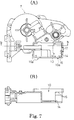
- FIG. 7 shows a gear frame, wherein (A) is a front elevational view and (B) is a cross-sectional bottom view taken along the line b-b in (A);
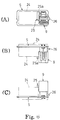
- FIG. 8 shows a holder, wherein (A) is a front elevational view, (B) is a side elevational view, and (C) is a bottom view;
- FIG. 9 is a partially disassembled perspective view showing the assembly process;
- FIG. 10 is a perspective view showing the state after the assembly is complete;
- FIG. 11 also shows a state after the assembling is completed, wherein (A) is a sectional bottom view, and (B) is a cross-sectional view taken along the line b-b in (A);
- FIG. 12 is a sectional view taken along the line X-X in FIG. 11;
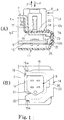
- FIG. 13 is a partially disassembled perspective view showing a wiper motor device according to the third embodiment; and
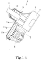
- FIG. 14 is a side elevational view, partly in section, of a wiper motor device according to a fourth embodiment.
-
- Referring to Figures 1 to 4 a
wiper motor device 1 is provided to wipe the rear window glass surface of a vehicle. Thewiper motor device 1 is disposed inside the body plate material of the vehicle (glass plate and body plate (not illustrated). The device comprises amotor portion 2 provided with an electric motor (not illustrated),gear portion 4 including a reduction mechanism (not illustrated), a link mechanism (not illustrated), an output shaft (which is the pivot axis of the wiper) 3, and adrive circuit portion 6 provided with acircuit board 5. etc. The electric motor is driven and controlled by circuits incorporated in thecircuit board 5, and the motive power of the motor is transmitted from theoutput shaft 3 via the reduction mechanism and the link mechanism. This basic construction is the same as that of conventional devices. - A
gear frame 7 accommodates theabovementioned gear portion 4. Theoutput shaft 3 is rotatably supported in asleeve 8 formed integrally with thegear frame 7, and the tip end of theoutput shaft 3, which protrudes from thesleeve 8, extends through an attaching hole (not illustrated) formed in the body plate material so that it protrudes outside the body (that is, outside the body plate material). The base end portion of a wiper arm (not illustrated) is connected to the protruding tip end portion of theshaft 3. Further, a grommet (not illustrated) is attached to the attaching hole through which theoutput shaft 3, extends and acts as a seal to prevent water from seeping into the through hole and into the body interior. - In the present embodiment, the wiper motor device I is, as shown in FIG. 3, attached to the body side so that the tip end side of the
output shaft 3 is extends obliquely upward when view in side elevational and thedrive circuit portion 6 is located obliquely downwardly of the base end portion of theoutput shaft 3. For convenience of explanation, the tip end side of theoutput shaft 3 will be referred to as "upward", and the base end side will be referred to as "downward" in a situation where the wiper motor device I is not attached to the body side. - The
drive circuit portion 6 is accommodated in anaccommodation casing 10, which is formed integrally with thegear frame 7, and wires (not illustrated) and aconnector 9, etc., to which an electric motor is connected are attached to thecircuit board 5. The upper side of theaccommodation casing 10 is open, and the upper opening is closed by acover 11. - The
cover 11 is formed to have aside portion 11b which depends downwardly from the outer circumferential edge of a plate-likeupper surface portion 11a. Further, a plurality oftongues 11c are formed to depend downwardly from the lower edge of the side portion llb.Engagement holes 11d are provided to be open on the tongues lie.Engagement claws 10a corresponding to the engagement holes lid of the cover are provided on the upper portion of the accommodation casing so as to protrude therefrom. When thecover 11 is placed over the upper opening of theaccommodation casing 10, thecover 11 is secured to theaccommodation casing 10 by engaging theengagement claws 10a in the engagement holes lid. - An extension portion lie is formed integrally with the
upper surface portion 11a of thecover 11 and is located in a position in which it surrounds the outer circumference of thesleeve 8 that pivotally supports theoutput shaft 3. Acylindrical portion 11f locates closely around the outer circumference of thesleeve 8 and is integrally formed with the extension portion lie. Thecylindrical portion 11f extends upwardly from theextension portion 11e. The upper end of thesleeve 8 protrudes from the upper end of thecylindrical portion 11f, and as described above, theoutput shaft 3 protrudes from the upper end of thesleeve 8. -
Reference numeral 12 indicates a waterproof cap. Thewaterproof cap 12 is generally cylindrical and has a diameter which increases stepwise downwardly (two steps in the present embodiment). The upper end portion of thecap 12 engages with a lower end portion of the protruding part ofoutput shaft 3 and contacts the circumference of the shaft in a slightly pressure-fitted state. The lower portion of thewaterproof cap 12 is located around the outer circumference of the upper part of thecylindrical portion 11f of theabovementioned cover 11, so that a labyrinth path is formed between the lower part of thewaterproof cap 12 and the upper part of thecylindrical portion 11f. -
Guide ribs 11g are formed on theupper surface portion 11a of thecover 11 in a state where thewiper motor device 1 is attached at the body side. Theguide ribs 11g can guide water flowing on theupper surface portion 11a so that the water does not flow into theengagement holes 11d. In the present embodiment, theguide ribs 11g are, as shown in FIG. 1, located inwardly of the engagement holes lid with respect to theoutput shaft 3. However, the configuration of the ribs is not limited to this arrangement. For example in a second embodiment as shown in FIG. 5, theguide ribs 11g may be arranged so as to surround theengagement holes 11d. That is, since theguide ribs 11g are provided, according to the attached state of thewiper motor device 1 and position of theengagement holes 11d, to guide water on the upper surface portion of the cover so that water flowing thereon does not flow into theengagement holes 11d, the shape and/or position of theguide ribs 11g are not limited to any particular configuration. - As shown in FIGS. 7 to 10, the
accommodation casing 10 is disposed at the lower part of the main surface (hereinafter referred to the front elevation) at the side from which theoutput shaft 3 of thegear frame 7 protrudes, and is formed so as to define a rectangular opening which is similar in shape to thecircuit board 5 but larger in size than thecircuit board 5. Aninsertion hole 14 into which aconnector 9 can be inserted is provided on the bottom wall of theaccommodation casing 10 and a cut-awayportion 15 is formed along three side walls of theinsertion hole 14 of theaccommodation casing 10. An externalforce receiving portion 16 that receives an external force applied to theconnector 9 is formed on the rear of the cut-awayportion 15. A twistingforce receiving portion 17 that receives a twisting force applied to theconnector 9 is formed at one side of the notchedportion 15. - In the first embodiment, a
holder 18 for thewiper motor device 1 is made of resin and is, as shown in FIG. 8, integrally formed so as to be bifurcated like a fork in its front elevational view. The inner spacing of a pair ofbifurcated insertion portions connector 9, wherein the pair of bifurcated insertion portions can be fitted onto the outer circumference of theconnector 9. Anengagement part 21 that looks roughly like an isosceles triangle in its front elevational view is formed to protrude inwardly at the tip end portion of the inside of one of the insertion portions (hereinafter referred to as a lower insertion portion). Theengagement part 21 is arranged to engage with the lower corner of thecoupler 9 when aholder 18 is fitted to theconnector 9, whereby theholder 18 itself is prevented from disengaging therefrom. A fixingpart 22 whose side elevational view is roughly rectangular is formed to extend at a right angle to bothinsertion portions holder 18, and a bendingpart 23 is bent to form an intermediate portion of the fixingpart 22 so that the tip end thereof can be moved in parallel to the direction of bothinsertion portions part 22 is set to be engaged with thecover 11 from the outside when theholder 18 is fitted to theconnector 9. In addition, as shown in FIG. 11(A), thebent part 23 is configured so that there is a gap between the inner circumferential side thereof and the outer wall of theaccommodation casing 10, whereby it is possible to prevent it from interfering with the edge part of the externalforce receiving portion 16. - When the
connector 9 is accommodated in theaccommodation casing 10, thecircuit board 5 is positioned with respect to its forward, vertical and left and right directions since the front main surface (hereinafter referred to the front surface) is brought into contact with the bottom (rear surface) of theaccommodation casing 10, and the outer circumference is brought into contact with the side wall internal surface of the four sides (hereinafter referred to the vertical and left and right sides) of theaccommodation casing 10. Also, as shown in FIG. 10, theconnector 9 protrudes from the notched portion of thegear frame 7, and the side (hereinafter referred to the left side) of acontroller 24 is brought into contact with the twistingforce receiving portion 17. - Subsequently, as the
holder 18 is fitted onto the outer circumference of theconnector 9 at the cut-awayportion 15, theholder 18 closes theinsertion hole 14 and assumes a state where it is engaged with a part of the rear surface of theconnector 9. Therefore, thecircuit board 5 is prevented by theholder 18 from coming off rearwardly. - In addition, as referred to in FIG. 11(B), since the
engagement part 21 of thelower insertion portion 20 of theholder 18 will be engaged with a part of the outer circumference of thecoupler 9, theholder 18 itself can be prevented from disengaging from the outer circumference of thecoupler 9. Further, the tip end portion of eachinsertion portions groove 15a secured downwardly of the twistingforce receiving portion 17 of the cut-awayportion 15, whereby theconnector 9 is prevented from moving out of theinsertion hole 14 even in the case where thegear frame 7 moves after theholder 18 is fitted to theconnector 9, and thecircuit board 5 can be prevented from falling out from theaccommodation casing 10. - A
wiper motor device 1 produced as described above is installed below the window of a vehicle, and when a mating coupler (not illustrated) wired at the vehicle side is connected to theconnector 9, an insertion force generated by the mating coupler indicated by the arrow F in FIG. 11(A) is applied to theconnector 9. If the insertion force F is applied to thecircuit board 5, there is a risk that thecircuit board 5 itself and the controller 24 (electric wires, electric components, and soldered parts) may be damaged, wherein the reliability of thecircuit board 5 is reduced. However, since, in the present embodiment, the externalforce receiving portion 16 of thegear frame 7 is engaged in theconnector 9 via theholder 18, the insertion force F of the mating coupler can be received by the externalforce receiving portion 16 of thegear frame 7 via theholder 18, wherein the insertion force F of the mating coupler can be prevented from being applied to thecircuit board 5, and it is possible to prevent thecircuit board 5 from being damaged by the insertion force of the mating coupler into theconnector 9. - Also, even though a twisting force indicated by the arrow X in FIG. 11(A) is applied when inserting the mating coupler into the
connector 9, the side of theconnector 9 is brought into contact with the twistingforce receiving portion 17, wherein theleft engagement piece 25 is brought into contact with the rear side of thegear frame 7, theright engagement piece 26 is brought into contact with the end portion of the accommodation casing opening 10b of thegear frame 7, and, as shown in FIG. 10, theextension portion 25a of theleft engagement piece 25 is engaged with the edge of the twistingforce receiving portion 17. As a result thegear frame 7 can receive stress applied to theconnector 9. Therefore, the twisting force X is prevented from being applied to thecircuit board 5. Also, thecircuit board 5 can be prevented in advance from being damaged by the twisting force X when inserting the mating coupler into theconnector 9. - When the mating coupler is disconnected from the
connector 9, the force F' is generated. Since theleft engagement piece 25 of theconnector 9 is brought into contact with the rear side of thegear frame 7 and theright engagement piece 26 is brought into contact with the end of the accommodation casing opening 10b of theconnector 9, thegear frame 7 does not directly receive the disconnecting force, whereby it is possible to prevent thecircuit board 5 in advance from being damaged. - Further, in this embodiment, since the cut-away
portion 15 is formed at the side wall of theinsertion hole 14 of theaccommodation casing 10, the weight of thegear frame 7 can be further lightened in comparison with a type such as shown in dot-dash line in Fig. 11(A) in which aportion 10c surrounding the entire circumference of theconnector 9 is formed at theinsertion hole 14 of thecoupler 9 of theaccommodation casing 10 of the gear frame, and theconnector 9 can be exposed at the cut-awayportion 15. Therefore, the operation of coupling the mating coupler into theconnector 9 can be facilitated. - A third embodiment is shown in FIG. 13. In this construction the
circuit board 5A is inserted into theaccommodation casing 10A, and theconnector 9A extends at a right angle with respect to the axial direction of theoutput shaft 3. Theconnector 9A is fixed laterally of thecircuit board 5A and is laterally inserted into theinsertion hole 14A of theaccommodation casing 10A from the rear. When thecircuit board 5A is accommodated in theaccommodation casing 10A, thecircuit board 5A is positioned with respect to the forward and four sides (hereinafter called vertical and left and right directions) of theaccommodation casing 10A since the front side main surface (hereinafter called the front side) is brought into contact with the bottom (rear side) of theaccommodation casing 10A and the outer circumference is brought into contact with the four internal sides of thecasing 10A. Thereafter, when thecover 11 is placed on thecasing 10A, thecover 11 presses thecircuit board 5A from the outside, wherein thecircuit board 5A is completely prevented from coming out from theaccommodation casing 10A. In this state. even though an insertion force and/or a twisting force are applied to thecoupler 9 when connector the mating coupler to theconnector 9A, thegear frame 7 can directly receive such forces from theconnector 9A because theflange portion 16A of thegear frame 7 is fitted in a retaining groove of theconnector 9A. Therefore, such forces will not be applied to thecircuit board 5A, and it is possible to prevent thecircuit board 5A from being damaged by such forces. - In a construction of the type described above, the
wiper motor device 1 is attached to the body side in such a way that thedrive circuit portion 6 is positioned downwardly of theoutput shaft 3. The extension portion lie is formed on thecover 11 to enclose the upper opening of theaccommodation casing 10, in which thedrive circuit portion 6 is accommodated, so as to extend to thesleeve 8 which pivotally supports theoutput shaft 3. Thecylindrical portion 11f that is fitted to the outer circumference of thesleeve 8 is made to extend upwardly from the extension portion lie, and the lower end of thewaterproof cap 12 pressure-fitted and attached to theoutput shaft 3 is externally fitted around the upper part of thecylindrical portion 11f. - As a result, even in the case where water seeps inside the body, for example, from the attaching hole portion of the body plate material along the
output shaft 3, such water flows, as shown in FIG. 3, onto theupper surface portion 11a along the outer circumferential side of thecylindrical portion 11f from the outer circumferential side of thewaterproof cap 12 and flows downward on theupper surface portion 11a. Accordingly, problems which might arise from water flowing between thegear frame 7 and theaccommodation casing 10 and invading theaccommodation casing 10 are prevented. Thus it is possible to effectively protect thecircuit board 5 in theaccommodation casing 10 from the effects of moisture. - In addition, since the
cover 11 is fixed to theaccommodation casing 10, thecylindrical portion 11f will not move at all. However, thewaterproof cap 12 is slightly pressure-fitted to theoutput shaft 3 and thus rotates along with theoutput shaft 3. Further, since a labyrinth path resulting from the edge of thecylindrical portion 11f overlapping that of thewaterproof cap 12 is employed, no adverse influence is applied to the drive of an electric motor by using thewaterproof cap 12, wherein it is possible to favorably provide a drip-proof effect. - Still further, in embodiments in accordance with the invention, since a construction is employed, in which water flowing downward on the
upper surface portion 11a of theabovementioned cover 11 is guided so as not to reach theengagement holes 11d by the guide rib llg formed on theupper surface portion 11a, it is possible to securely prevent water from seeping through theengagement holes 11d, wherein a further improved drip-proof structure can be achieved. - Also, it will be appreciated that the present invention is not limited to the abovementioned embodiments. Without providing a waterproof cap as a separate member, the upper end portion of the cover
cylindrical portion 11f may he constructed as an integral structure in which it is fitted to theoutput shaft 3 protruding from the upper end of thesleeve 8 in a drip-proof state, wherein effects similar to the above can be achieved.
Claims (3)
- A drip-proof structure for a wiper motor device in which a drive circuit portion of a wiper motor is disposed adjacent to an output shaft of the wiper motor, wherein the structure includes a cover for shielding an upper opening of an accommodation casing for accommodating said drive circuit portion, said cover having an extension portion which is arranged and configured to receive any moisture which drips from said output shaft.
- A drip-proof structure for a wiper motor device according to Claim 1, wherein a cylindrical portion fitted to the outer circumference of said output shaft is formed on said extension portion of said cover, and the base side of a waterproof cap attached to said output shaft is located around the tip end side of said cylindrical portion to create a drip-proof structure.
- A drip-proof structure for a wiper motor device according to Claim 1 or 2, wherein a guide rib or ribs is provided and formed on the upper surface of said cover, said guide rib or ribs being arranged to guide water flowing on said upper surface so as to prevent said water from flowing to a fixing portion which fixes said accommodation casing and cover.
Applications Claiming Priority (4)
| Application Number | Priority Date | Filing Date | Title |
|---|---|---|---|
| JP32119999A JP3836281B2 (en) | 1999-11-11 | 1999-11-11 | Drip-proof structure of wiper motor device |
| JP32119999 | 1999-11-11 | ||
| JP2000106144A JP3764839B2 (en) | 2000-04-07 | 2000-04-07 | Motor with worm gear speed reducer |
| JP2000106144 | 2000-04-07 |
Publications (3)
| Publication Number | Publication Date |
|---|---|
| EP1099608A2 true EP1099608A2 (en) | 2001-05-16 |
| EP1099608A3 EP1099608A3 (en) | 2003-04-16 |
| EP1099608B1 EP1099608B1 (en) | 2009-03-04 |
Family
ID=26570400
Family Applications (1)
| Application Number | Title | Priority Date | Filing Date |
|---|---|---|---|
| EP00309910A Expired - Lifetime EP1099608B1 (en) | 1999-11-11 | 2000-11-08 | Water-drop proof structure for wiper motor apparatus |
Country Status (3)
| Country | Link |
|---|---|
| US (1) | US6410849B1 (en) |
| EP (1) | EP1099608B1 (en) |
| DE (1) | DE60041683D1 (en) |
Cited By (1)
| Publication number | Priority date | Publication date | Assignee | Title |
|---|---|---|---|---|
| CN107640127A (en) * | 2016-07-22 | 2018-01-30 | 丰田自动车株式会社 | The mounting structure of waterproof cover and installation method, wiper device in wiper device |
Families Citing this family (9)
| Publication number | Priority date | Publication date | Assignee | Title |
|---|---|---|---|---|
| ITMI20010939A1 (en) * | 2001-05-08 | 2002-11-08 | Itw Ind Components Srl | TERMINAL BLOCK OF COMPLEX SHAPE, IN PARTICULAR FOR HIGH CURRENT APPLICATIONS |
| US7135801B2 (en) * | 2004-08-24 | 2006-11-14 | Asmo Co., Ltd. | Motor apparatus having rotational position detector |
| JP4319629B2 (en) * | 2005-01-21 | 2009-08-26 | アスモ株式会社 | Wiper motor and wiper device |
| CN101161514B (en) * | 2007-08-30 | 2010-06-16 | 奇瑞汽车股份有限公司 | A rain shaving electrical machine and its water-proof method |
| DE102007055642A1 (en) * | 2007-11-21 | 2009-05-28 | Robert Bosch Gmbh | wiper device |
| US8234746B2 (en) * | 2008-09-22 | 2012-08-07 | Robert Bosch Gmbh | Water blocker for wiper system |
| DE102009027521B4 (en) | 2009-07-08 | 2019-05-23 | Robert Bosch Gmbh | Drive unit of a windshield wiper device in a vehicle |
| JP5759909B2 (en) * | 2012-01-23 | 2015-08-05 | アンデン株式会社 | Frame structure |
| JP6462313B2 (en) * | 2014-10-27 | 2019-01-30 | 株式会社ミツバ | Drive device |
Family Cites Families (12)
| Publication number | Priority date | Publication date | Assignee | Title |
|---|---|---|---|---|
| DE3123859A1 (en) * | 1981-06-16 | 1982-12-30 | SWF-Spezialfabrik für Autozubehör Gustav Rau GmbH, 7120 Bietigheim-Bissingen | WINDOW WIPER, ESPECIALLY FOR MOTOR VEHICLES |
| US4487328A (en) * | 1982-10-29 | 1984-12-11 | Show-Pak, Incorporated | Container case |
| GB8614636D0 (en) * | 1986-06-16 | 1986-07-23 | Lundquist R | Electrical terminal box |
| DE3632694A1 (en) * | 1986-09-26 | 1988-04-07 | Swf Auto Electric Gmbh | Electric motor, especially a wiper motor for motor vehicles |
| US5177325A (en) * | 1989-12-20 | 1993-01-05 | A. J. Giammanco & Associates, Inc. | Housing for electric transformer |
| DE9206269U1 (en) * | 1992-05-09 | 1993-09-09 | Bosch Gmbh Robert | Electromotive drive device |
| JP2576190Y2 (en) | 1992-09-02 | 1998-07-09 | 自動車電機工業株式会社 | Wiper pivot mounting structure |
| FR2699758B1 (en) * | 1992-12-17 | 1995-02-03 | Valeo Systemes Dessuyage | Drive unit for a motor vehicle wiper. |
| DE19548829A1 (en) * | 1995-06-29 | 1997-01-09 | Teves Gmbh Alfred | Plastic housing |
| FR2748436B1 (en) * | 1996-05-07 | 1998-07-31 | Valeo Systemes Dessuyage | MOTOR REDUCER FOR WINDSCREEN WIPER WITHOUT SHAFT LOCKING STOP |
| DE19711980C2 (en) * | 1997-03-12 | 2001-11-08 | Krone Gmbh | Stationary housing with plastic wall elements |
| JP2000023423A (en) * | 1998-06-30 | 2000-01-21 | Ykk Corp | Brushless motor rotation angle detector and brushless motor employing the same |
-
2000
- 2000-11-08 DE DE60041683T patent/DE60041683D1/en not_active Expired - Lifetime
- 2000-11-08 EP EP00309910A patent/EP1099608B1/en not_active Expired - Lifetime
- 2000-11-09 US US09/708,481 patent/US6410849B1/en not_active Expired - Fee Related
Non-Patent Citations (1)
| Title |
|---|
| None |
Cited By (2)
| Publication number | Priority date | Publication date | Assignee | Title |
|---|---|---|---|---|
| CN107640127A (en) * | 2016-07-22 | 2018-01-30 | 丰田自动车株式会社 | The mounting structure of waterproof cover and installation method, wiper device in wiper device |
| CN107640127B (en) * | 2016-07-22 | 2020-05-01 | 丰田自动车株式会社 | Structure and method for attaching waterproof cover to wiper device, and wiper device |
Also Published As
| Publication number | Publication date |
|---|---|
| US6410849B1 (en) | 2002-06-25 |
| EP1099608B1 (en) | 2009-03-04 |
| DE60041683D1 (en) | 2009-04-16 |
| EP1099608A3 (en) | 2003-04-16 |
Similar Documents
| Publication | Publication Date | Title |
|---|---|---|
| KR101463132B1 (en) | Connector for flat cables | |
| US5063317A (en) | Electric motor, especially an electric small-power motor for driving wiper systems of motor vehicles | |
| US5528093A (en) | Commutator-motor gear/drive unit, in particular a window-lift drive for a motor vehicle | |
| KR20020096847A (en) | Ultrasonic obstacle detector and method of assembling the same | |
| EP1099608B1 (en) | Water-drop proof structure for wiper motor apparatus | |
| US7679236B2 (en) | Electric actuator | |
| JP2009541919A (en) | Electrical connector | |
| US7540749B1 (en) | Connector assemblies and systems | |
| JPH08192680A (en) | Connecting construction between drive unit and harness in motor-driven remote control mirror | |
| KR20230049041A (en) | Cable protection cover for increasing pull-out resistance | |
| US6689957B2 (en) | Liquid-blocking connector | |
| US4592611A (en) | Electrical connector intended for use in confined areas | |
| JPH11176511A (en) | Electric connector | |
| US6051794A (en) | Waterproofing member for wire harness connecting portion | |
| EP1804340B1 (en) | Fixation structure for rear cover | |
| JP3751769B2 (en) | Board connector connection structure | |
| US5944558A (en) | Connector with projected rib to guide the holder and the jig to control the connectivity of the terminal | |
| JPH11121076A (en) | Connector with terminal fixing tool | |
| US5842884A (en) | Male connector | |
| CN108808991B (en) | Watertight assembly for a vehicle window regulator | |
| WO2023008041A1 (en) | Charging connector | |
| JPH09237649A (en) | Connector | |
| JP2004363100A (en) | Electric connector | |
| JPH07296879A (en) | Electric connector | |
| JP4372970B2 (en) | motor |
Legal Events
| Date | Code | Title | Description |
|---|---|---|---|
| PUAI | Public reference made under article 153(3) epc to a published international application that has entered the european phase |
Free format text: ORIGINAL CODE: 0009012 |
|
| AK | Designated contracting states |
Kind code of ref document: A2 Designated state(s): AT BE CH CY DE DK ES FI FR GB GR IE IT LI LU MC NL PT SE TR |
|
| AX | Request for extension of the european patent |
Free format text: AL;LT;LV;MK;RO;SI |
|
| PUAL | Search report despatched |
Free format text: ORIGINAL CODE: 0009013 |
|
| AK | Designated contracting states |
Designated state(s): AT BE CH CY DE DK ES FI FR GB GR IE IT LI LU MC NL PT SE TR |
|
| AX | Request for extension of the european patent |
Extension state: AL LT LV MK RO SI |
|
| 17P | Request for examination filed |
Effective date: 20030530 |
|
| 17Q | First examination report despatched |
Effective date: 20030709 |
|
| AKX | Designation fees paid |
Designated state(s): DE GB |
|
| GRAP | Despatch of communication of intention to grant a patent |
Free format text: ORIGINAL CODE: EPIDOSNIGR1 |
|
| GRAS | Grant fee paid |
Free format text: ORIGINAL CODE: EPIDOSNIGR3 |
|
| GRAA | (expected) grant |
Free format text: ORIGINAL CODE: 0009210 |
|
| AK | Designated contracting states |
Kind code of ref document: B1 Designated state(s): DE GB |
|
| REG | Reference to a national code |
Ref country code: GB Ref legal event code: FG4D |
|
| REF | Corresponds to: |
Ref document number: 60041683 Country of ref document: DE Date of ref document: 20090416 Kind code of ref document: P |
|
| PLBE | No opposition filed within time limit |
Free format text: ORIGINAL CODE: 0009261 |
|
| STAA | Information on the status of an ep patent application or granted ep patent |
Free format text: STATUS: NO OPPOSITION FILED WITHIN TIME LIMIT |
|
| PGFP | Annual fee paid to national office [announced via postgrant information from national office to epo] |
Ref country code: DE Payment date: 20091105 Year of fee payment: 10 |
|
| 26N | No opposition filed |
Effective date: 20091207 |
|
| GBPC | Gb: european patent ceased through non-payment of renewal fee |
Effective date: 20091108 |
|
| PG25 | Lapsed in a contracting state [announced via postgrant information from national office to epo] |
Ref country code: GB Free format text: LAPSE BECAUSE OF NON-PAYMENT OF DUE FEES Effective date: 20091108 |
|
| REG | Reference to a national code |
Ref country code: DE Ref legal event code: R119 Ref document number: 60041683 Country of ref document: DE Effective date: 20110601 Ref country code: DE Ref legal event code: R119 Ref document number: 60041683 Country of ref document: DE Effective date: 20110531 |
|
| PG25 | Lapsed in a contracting state [announced via postgrant information from national office to epo] |
Ref country code: DE Free format text: LAPSE BECAUSE OF NON-PAYMENT OF DUE FEES Effective date: 20110531 |