TECHNICAL FIELD
-
The present invention relates to a network connection
recognition method suited for recognizing a device connected by
a bus line of, for example, the IEEE (The Institute of
Electrical and Electronics Engineers) 1394 scheme, and a
terminal device for network connection to which this network
recognition method has been applied.
BACKGROUND ART
-
AV devices capable of transmitting information to each
other via a network using a serial data bus of the IEEE 1394
scheme have been developed. In this network, an AV device
connected to the network can be controled by using a
predetermined command (AV/C Command Transaction Set). In the
ensuing description, this command is referred to as AV/C
command. Details of the AV/C Command will be described later.
-
As conventional AV devices connected via the bus line of
the IEEE 1394 scheme, there are digital video camera devices and
digital video tape recording and playback devices of, for
example, a standard called DV scheme. In other words, two
recording and playback devices are prepared and connected via a
bus line which conforms to the IEEE 1394 scheme. Digital video
data reproduced from one device is transmitted by this bus line
and recorded by the other device.
-
By thus connecting AV devices via the bus line of the
IEEE 1394 scheme, large capacity data such as digital video data
can be transmitted in real time and editing of video data or the
like can be conducted efficiently.
Data which can be transmitted via the bus line of the
-
IEEE 1394 scheme is not limited to the above described digital
video data, but various kinds of other digital data can be
transmitted. Various data handled by AV devices can be
transmitted. In other words, a large number of devices (for
example, 63 devices) can be connected to one network via the bus
line of the IEEE 1394 scheme. Among a large number of devices,
video data, audio data, and control data can be transmitted.
-
For example, it becomes possible to connect an IRD
(Integrated Receiver Decoder) serving as a receiving device for
receiving digital satellite broadcast to a digital video tape
recording and playback device referred to as DVCR (Digital Video
Cassette Recorder) using a magnetic tape as a recording medium
via the bus line of the IEEE 1394 scheme, and record video data
received by the IRD, by using the DVCR. Furthermore, it becomes
possible to connect a digital audio disc recording and playback
device using an magneto-optical disc called MD (Mini Disc) as a
recording medium to the same bus line, and record audio data
received by the IRD, by using the audio disc recording and
playback device (MD device).
-
In the case where a large number of devices are thus
connected to one network, a device for controlling data
transmission within the network in the IEEE 1394 scheme provides
all devices in the network with individual node IDs, and manages
the transmitting source and receiving destination by using the
node IDs. As a result, data transmission between specific
devices in the network becomes possible.
-
Besides provision of the above described node IDs, the
device for controlling the data transmission in the network
needs to discriminate the kind of each of connected devices and
effect control according to the discriminated kind. For
example, in the case of a device corresponding to a command such
as the above described AV/C command, it is necessary to transmit
a predetermined command or the like prescribed in the scheme,
transmit data concerning the function possessed by each device,
and collect the transmitted data.
-
The work of provision of the node ID and discrimination
of the device kind is conducted when the bus line included in
the network is reset. The bus line is reset when there is an
alteration in devices connected to the bus line, besides when a
new network is formed. In the case where the network
configuration is altered at any time, there is a possibility
that bus reset is applied frequently.
-
In the case where the number of devices connected to the
bus line included in the network is large as described above,
there is a problem that a heavy burden is cast upon the work of
collecting data of all devices and the time required for the
processing also becomes long.
DISCLOSURE OF THE INVENTION
-
An object of the present invention is to simplify the
work of discriminating a device at the time of bus resetting or
the like, in the case where a network of the IEEE 1394 scheme or
the like is formed.
- A first invention is a network connection recognition
method for recognizing a device connected to a predetermined
network, including: a device recognition step of recognizing a
device connected to the network; a data acquisition step of
acquiring predetermined data from the recognized device; and a
comparison step of comparing the predetermined data obtained
from the recognized device with predetermined data previously
collected and stored, wherein when in the comparison step the
predetermined data obtained from the recognized device has
coincided with the predetermined data previously collected and
stored, data concerning a device corresponding to the stored
predetermined data is utilized as data concerning the recognized
device. Therefore, by comparing predetermined data transmitted
from the recognized device With stored data, judging upon
coincidence the device to be a previously connected device, and
using data concerning the device previously collected and
stored, it becomes unnecessary to collect data concerning the
device from the device.
- A second invention is the network connection recognition
method of the first invention,
wherein the predetermined data is an identifier capable
of identifying each device individually. By doing so, a device
can be discriminated simply by using an identifier. - A third invention is the network connection recognition
method of the first invention,
including a data collection step of collecting data
concerning the device when the predetermined data obtained from
the recognized device has not coincided with predetermined data
previously collected and stored. By doing so, the step of
collecting data concerning the device is executed only for a
device newly connected to the network. The time and processes
required for data collection can thus be reduced. - A fourth invention is the network connection recognition
method of the third invention,
wherein the data collection step includes: an inquiry
command sending step of sending a command for inquiring a unit
type or a subunit type to the device; and
- a discriminating step of discriminating the unit type or
the subunit type of the device based on a response from the
device. By doing so, it becomes possible to certainly know the
unit type or subunit type implemented in the device.
- A fifth invention is the network connection recognition
method of the fourth invention,
wherein the data collection step further includes:
- a type corresponding command sending step of sending a
command corresponding to the discriminated type; and
- a device kind determining step for determining the
device kind based on a response obtained by the type
corresponding command sending step. By doing so, it becomes
possible to discriminate the device connected to the network
more certainly by the type corresponding command sending step
and device kind determining step.
- A sixth invention is the network connection recognition
method of the first invention, wherein the device recognition
step of recognizing a device connected to the network is
conducted when a bus line forming the network is reset. By
doing so, it becomes possible to conduct data collection of each
device at the time of bus resetting, for example, in the case
where the network configuration is changed, with a reduced
burden in a short time.
- A seventh invention is the network connection
recognition method of the first invention,
including data deleting step of deleting the stored
predetermined data when predetermined data previously collected
and stored does not coincide with any of the predetermined data
obtained from the recognized device. By doing so, storage of
predetermined data concerning devices which have been
disconnected from the network is deleted. Data which are not
required for control of devices in the network are thus deleted
efficiently. - An eighth invention is the network connection
recognition method of the first invention,
including data deleting step of deleting data concerning
a device corresponding to the stored predetermined data when
predetermined data previously collected and stored does not
coincide with any of the predetermined data obtained from the
recognized device. By doing so, storage of the data concerning
devices which have been disconnected from the network is
deleted. Data which are not required for control of devices in
the network are thus deleted efficiently. - A ninth invention is a network connection terminal
device connected to a predetermined network, the network
connection terminal device including:
- a storage section for storing data concerning a device
connected via the network; and
- a control section responsive to recognition of a device
connected via the network, for comparing predetermined data
transmitted from the device with data stored in the storage
section, causing data concerning devices incurring
noncoincidence in the comparison to be transmitted, and causing
stored data of the storage section to be updated. When a device
which does not coincide with predetermined data stored in the
storage section is recognized, therefore, data concerning the
device is acquired. It thus becomes possible to collect only
the data concerning newly connected devices efficiently and
simply.
- A tenth invention is a network connection terminal
device connected to a predetermined network, the network
connection terminal device including:
- device recognition means for recognizing a device
connected to the network;
- data acquisition means for acquiring predetermined data
from the recognized device; and
- comparison means for comparing the predetermined data
obtained from the recognized device with predetermined data
previously collected and stored,
wherein when in the comparison means the predetermined
data obtained from the recognized device has coincided with the
predetermined data previously collected and stored, data
concerning a device corresponding to the stored predetermined
data is utilized as data concerning the recognized device.
Therefore, by comparing predetermined data transmitted from the
recognized device with stored data, judging upon coincidence the
device to be a previously connected device, and using data
concerning the device previously collected and stored, it
becomes unnecessary to collect data concerning the device from
the device. Thus, the burden required for data collection from
the devices connected to the network can be reduced. In
addition, a terminal device capable of shortening the time
required for the processing is obtained. - An eleventh invention is the network connection terminal
device of the tenth invention, wherein the predetermined data is
an identifier capable of identifying each device individually.
By doing so, a device can be discriminated simply by using an
identifier.
- A twelfth invention is the network connection terminal
device of the tenth invention, including:
- command output means for generating and outputting a
first command to inquire of a device connected via the network
about a unit type or a subunit type; and
- discrimination means for receiving a response to the
first command, and discriminating a unit type or a subunit type
of the device based on the response. By doing so, it becomes
possible to certainly know the unit type or subunit type
implemented in the connected device.
- A thirteenth invention is the network connection
terminal device of the twelfth invention, including:
- command output means for generating and outputting a
second command corresponding to a unit type or a subunit type of
the device; and
- receiving means for receiving a response to the second
command from the device. By doing so, it becomes possible to
discriminate the device connected to the network more certainly
by generation of the first command and the second command in the
command output means.
- A fourteenth invention is the network connection
terminal device of the tenth invention,
wherein the device recognition means conducts processing
for recognizing a device connected via the network when the
device recognition means has detected that a bus line forming
the network is reset. By doing so, it becomes possible to
conduct data collection of each connected device at the time of
bus resetting, for example, in the case where the network
configuration to which the terminal device is connected is
changed, with a reduced burden in a short time. -
BRIEF DESCRIPTION OF DRAWINGS
-
- FIG. 1 is a block diagram showing a configuration
example of a whole system according to an embodiment of the
present invention.
- FIG. 2 is a block diagram showing a configuration
example of a digital satellite broadcast receiver.
- FIG. 3 is a block diagram showing a configuration
example of a video recording and playback device.
- FIG. 4 is a block diagram showing a configuration
example of an audio recording and playback device.
- FIG. 5 is a diagram showing an example of a frame
structure prescribed by the IEEE 1394 scheme.
- FIG. 6 is a diagram showing an example of a structure of
an address space of the CRS architecture.
- FIG. 7 is a diagram showing examples of positions,
names, and functions of principal CRSs.
- FIG. 8 is a diagram showing configuration examples of
plug control registers.
- FIG. 9 is a diagram showing configuration examples of
oMPR, oPCR, iMPR, and iPCR.
- FIG. 10 is a diagram showing an example of relations
among plugs, plug control registers, and transmission channels.
- FIG. 11 is a diagram showing an example of a data
structure using a hierarchical structure of descriptors.
- FIG. 12 is a diagram showing an example of a data
structure of descriptors.
- FIG. 13 is a diagram showing an example of a generation
ID of FIG. 12.
- FIG. 14 is a diagram showing an example of a list ID of
FIG. 12.
- FIG. 15 is a diagram showing an example of a stack model
of an AV/C command.
- FIG. 16 is a diagram showing an example of a relation
between commands and responses of an AV/C command.
- FIG. 17 is a diagram showing an example of a relation
between commands and responses of an AV/C command in more
detail.
- FIG. 18 is a diagram showing an example of a data
structure of an AV/C command.
- FIG. 19 is a diagram showing a concrete example of an
AV/C command.
- FIG. 20 is a diagram showing concrete examples of a
command and a response of an AV/C command.
- FIG. 21 is a flow chart showing an example of device
discrimination processing according to an embodiment of the
present invention.
- FIG. 22 is a flow chart showing an example of device
information acquisition processing according to an embodiment of
the present invention.
- FIG. 23 is a diagram showing an example of a device
information table according to an embodiment of the present
invention.
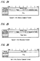
- FIG. 24 is a diagram showing an example of a format of a
subunit-info-command according to an embodiment of the present
invention.
- FIG. 25 is a diagram showing an example of a format of a
response to a subunit-info-command according to an embodiment of
the present invention.
- FIG. 26 is a diagram showing an example of a format of a
unit-info-command according to an embodiment of the present
invention.
- FIG. 27 is a diagram showing an example of a format of a
response to a unit-info-command according to an embodiment of
the present invention.
- FIG. 28 is a diagram showing an example of a subunit
type according to an embodiment of the present invention.
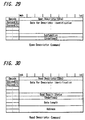
- FIG. 29 is a diagram showing an example of a format of
an open descriptor command according to an embodiment of the
present invention.
- FIG. 30 is a diagram showing an example of a format of a
read descriptor command according to an embodiment of the
present invention.
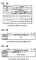
- FIG. 31 is a diagram showing an example of a descriptor
of a disc subunit according to an embodiment of the present
invention.
- FIG. 32 is a diagram showing a data configuration
example of a medium type of a disc subunit descriptor.
- FIG. 33 is a diagram showing an example of a format of a
tape playback command according to an embodiment of the present
invention.
- FIG. 34 is a diagram showing a format example of a
response to a tape playback command according to an embodiment
of the present invention.
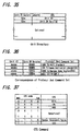
- FIG. 35 is a diagram showing an example of a unit
directory according to another embodiment of the present
invention.
- FIG. 36 is a diagram showing an example of
correspondence between protocols and command sets according to
another embodiment of the present invention.
- FIG. 37 is a diagram showing an example of a CTS code
according to another embodiment of the present invention.
- FIG. 38 is a diagram showing an example of key data
according to still another embodiment of the present invention.
-
BEST MODE FOR CARRYING OUT THE INVENTION
-
Hereafter, an embodiment of the present invention will
be described by referring to accompanying drawing.
-
A configuration example of a network system to which the
present invention has been applied will now be described by
referring to FIG. 1. In this network system, a plurality of
devices are connected via a serial data bus 1 (hereafter
referred to simply as bus 1) of the IEEE 1394 scheme. In FIG.
1, there is shown an example in which four AV devices 100, 200,
300 and 400 are prepared and three AV devices 100, 200 and 300
among them are connected. It is now assumed that devices
connected to the bus 1 are devices each having a terminal for
connection to a bus of the IEEE 1394 scheme, and the devices are
an IRD (Integrated Receiver Decoder) 100 serving as a digital
satellite broadcast receiver, a DVCR (Digital Video Cassette
Recorder) 200 serving as a digital video recording and playback
device, and an MD (Mini Disc) device 300 serving as a digital
audio recording and playback device. In the state shown in FIG.
1, two MD (Mini Disc) devices 300 and 400 are prepared, and only
the first MD device 300 is connected to the bus 1. The second
MD device 400 is not connected to the bus 1 at this time.
-
Here, electronic devices such as the IRD 100, DVCR 200,
and MD devices 300 and 400 which can be connected to the bus 1
are called units. Between units, information stored in the
units can be mutually read and written by using a command and a
descriptor prescribed by AV/C Digital Interface Command Set
General Specification (hereafter referred to as AV/C command) of
the AV/C Command Transaction Set. Details of the AV/C command
are described in AV/C Digital Interface Command Set General
Specification opened to the public in 1394 Trade Association.
In the AV/C command, each of functions that the unit has is
called subunit. Furthermore, each of functions that the unit
has is called subunit.
-
The IRD 100 for receiving and decoding digital satellite
broadcast or the like has a parabolic antenna 11 connected
thereto. A digital tuner 12 connected to the parabolic antenna
11 conducts processing for receiving a signal of a predetermined
channel and decoding it. In this case, a controller 13
incorporated in the IRD 100 effects control concerning the
receiving operation such as receiving and decoding.
-
As channels that the IRD 100 can receive, there are
audio channels from which only audio data such as tunes are
obtained, and data channels from which various data such as data
for web perusal of the Internet are obtained, besides video
channels (so-called channels for ordinary television broadcast)
from which video data and audio data annexed to the video data
are obtained. As audio data transmitted by audio channels,
there are audio data modulated by a typical method such as the
MPEG scheme, and channels from which audio data subjected to
high efficiency compression encoding such as ATRAC (Adaptive
Transform Acoustic Coding) scheme are obtained.
-
Furthermore, data transmission with the IRD 100 via the
bus 1 is also controlled by the controller 13. In data
transmission via the bus 1, the controller 13 is adapted to be
able to control operation of other devices 200 and 300 connected
by the bus 1 by using commands prescribed in the above described
AV/C command. For example, the controller 13 can transmit video
data and audio data of a video channel received by the IRD 100
to the DVCR 200, and control the recording operation in the DVCR
200 to record video data and the like on a video tape in a video
cassette mounted thereon. Thus video recording can be
performed. Furthermore, the controller 13 transmits audio data
of an audio channel received by the IRD 100 to the MD device
300, and controls audio recording operation in the MD device 300
to record audio data on a magneto-optical disc mounted thereon.
When conducting manual reservation operation for the video or
audio recording on the IRD 100, it is also possible to, for
example, display a program guide picture for EPG (Electric
Program Guide) on a television receiver (not shown) connected to
the IRD 100 and perform reservations by manually operating a GUI
(Graphical User Interface) on the basis of the display of the
program guide picture on the screen.
-
The DVCR 200 is a tape recording and playback device
capable of recording video data, audio data, and data annexed to
them on a videotape as digital data and reproducing those data
from the videotape. Herein, it is assumed that the DVCR 200 is
a recording and playback device using a medium having a format
called D-VHS. A controller 21 of the DVCR 200 accepts user's
manual operation for ordering video recording or playback or
manual operation for reserving video recording, and controls the
whole DVCR 200. On the basis of the control of the controller
21, an analog tuner 22 extracts a signal of a predetermined
channel from inputted analog signals, converts the signal to
digital data, and supplies the digital data to a tape recording
and playback section 23. The tape recording and playback
section 23 records video data and audio data supplied from the
analog tuner 22, or video data and audio data supplied from the
IRD 100 or the like via the bus 1 on a video tape.
-
The MD device 300 is a disc recording and playback
device capable of recording audio data and data annexed to the
audio data on a magneto-optical disc having a format called mini
disc (MD) as digital data and of reproducing the digital data
therefrom. A controller 31 of the MD device 300 accepts user's
manual operation for ordering audio recording or playback or
manual operation for reserving audio recording, and controls the
whole MD device 300. A disc recording and playback section 32
records audio data and so on inputted from the bus 1 or another
input section on a magneto-optical disc. As for recording on
the disc in this case, the audio data and so on are recorded as
data subjected to compression encoding by using the ATRAC
scheme. If audio data transmitted via the bus 1 is data of the
ATRAC scheme, therefore, the transmitted audio data is recorded
on the disc as it is.
-
The MD device 400 which is not connected to the bus 1 in
the state illustrated in FIG. 1 is also a disc recording and
playback device having basically the same configuration as that
of the MD device 300. In other words, the MD device 400 is a
disc recording and playback device capable of recording audio
data and data annexed to the audio data on a magneto-optical
disc having a format called mini disc (MD) as digital data and
of reproducing the digital data therefrom. The MD device 400
includes a controller 41 and a disc recording and playback
section 42. In addition, the MD device 400 includes a terminal
for connection to the bus 1. When this terminal is connected to
the bus 1, the MD device 400 can conduct data transmission via
the bus 1.
-
Each of the controllers 13, 21, 31 and 41 respectively
of the devices 100, 200, 300 and 400 includes a storage section
for storing an AV/C descriptor set for the device. In addition,
data such as a command required to read and write the descriptor
are also stored in the storage section.
-
FIG. 2 is a diagram showing a concrete configuration
example of the IRD 100. A broadcast radio wave from a satellite
is received by the antenna 8, inputted to a terminal 100a, and
supplied to a tuner 101 serving as program selection means
provided in the IRD 100. In the IRD 100, respective circuits
operate under the control of a central control unit (CPU) 111.
A signal of a predetermined channel is derived by the tuner 101.
The received signal derived by the tuner 101 is supplied to a
descramble circuit 102. On the basis of encryption key
information of a contracted channel stored in an IC card (not
shown) which has been inserted into the main body of the IRD
100, the descramble circuit 102 takes out only multiplexed data
of the contracted channel (or a channel which is not encrypted)
from among the received data, and supplies the multiplexed data
to a demultiplexer 103.
-
The demultiplexer 103 rearranges supplied multiplexed
data for each channel, takes out only a channel specified by the
user, sends a video stream formed of packets of video portions
to an MPEG video decoder 104, and sends an overlap stream formed
of packets of audio portions to an MPEG audio decoder 109.
-
The MPEG video decoder 104 restores video data before
being subjected to compression encoding by decoding the video
stream, and sends the video data to an NTSC encoder 106 via an
adder 105. The NTSC encoder 106 converts video data to a
luminance signal and a color difference signal of the NTSC
scheme, and sends the luminance signal and the color difference
signal to a digital to analog converter 107 as video data of the
NTSC scheme. The digital to analog converter 107 converts NTSC
data to an analog video signal, and supplies the analog video
signal to a connected television receiver (not shown).
-
The IRD 100 of the present example includes a GUI data
generation section 108 for generating various video data for
display for graphical user interface (GUI) under the control of
the CPU 111. The video data (display data) for GUI generated by
the GUI data generation section 108 is supplied to the adder
105, and superimposed on video data outputted from the MPEG
video decoder 104. Thus the image for GUI is superimposed on
the image of the received broadcast.
-
An MPEG audio decoder 109 restores PCM audio data before
being subjected to compression encoding by decoding the audio
stream, and sends the PCM audio data to a digital to analog
converter 110.
-
The digital to analog converter 110 converts PCM audio
data to an analog signal to generate an L-Ch audio signal and an
R-Ch audio signal. The L-Ch audio signal and the R-Ch audio
signal are outputted as a sound via a speaker (not shown) of a
connected audio playback system.
-
Furthermore, the IRD 100 of the present example has such
a configuration that the video stream and the audio stream
extracted by the demultiplexer 103 can be supplied to an IEEE
1394 interface section 112 and sent to the bus line 1 of the
IEEE 1394 scheme connected to the interface section 112. The
received video stream and audio stream are sent out in an
isochronous transfer mode. When the GUI data generation section
108 is generating video data for GUI, the video data is supplied
to the interface section 112 via the CPU 111 and the video data
for GUI can be sent out from the interface section 112 to the
bus line 1.
-
A work RAM 113 and a RAM 114 are connected to the CPU
111. Control processing is conducted by using these memories.
Furthermore, a manual operation order from a manual operation
panel 115 and a remote control signal from an infrared rays
receiving section 116 are supplied to the CPU 111, and operation
based upon various manual operations can be executed.
Furthermore, the CPU 111 can distinguish command and responses
transmitted from the bus line 1 to the interface section 112.
-
FIG. 3 is a block diagram showing a configuration
example of the DVCR 200.
-
As for the configuration of a recording system, digital
broadcast data obtained by receiving a predetermined channel in
a tuner 201 incorporated in the DVCR 200 is supplied to an MPEG
(Moving Picture Experts Group) encoder 202, and converted to
video data and audio data of a scheme suitable for recording,
such as the MPEG 2 scheme. If the received broadcast data is
data of the MPEG 2 scheme, the processing in the encoder 202 is
not conducted.
-
Data encoded by the MPEG encoder 202 is supplied to a
recording and playback section 203, and subjected to processing
for recording. The data to be recorded thus processed is
supplied to a recording head included in a rotary head drum 204,
and recorded on a magnetic tape in a tape cassette 205.
-
As for an analog video signal and audio signal inputted
from the outside, they are converted to digital data by an
analog to digital converter 206, converted to video data and
audio data of, for example, the MPEG 2 scheme, by the MPEG
encoder 202, supplied to the recording and playback section 203,
and subjected to processing for recording. The data to be
recorded thus processed is supplied to the recording head
included in the rotary head drum 204, and recorded on the
magnetic tape in the tape cassette 205.
-
As for the configuration of a playback system, a signal
obtained by playing back the magnetic tape in the tape cassette
tape 205 by using the rotary head drum 204 is subjected to
playback processing in the recording and playback section 203 to
produce video data and audio data. The video data and the audio
data are supplied to an MPEG decoder 207, and decoded from, for
example, the MPEG 2 scheme. The decoded data is supplied to a
digital to analog converter 208. An analog video signal and an
analog audio signal thus obtained are outputted to the outside.
-
The DVCR 200 includes an interface section 209 for
connection to a bus of the IEEE 1394 scheme. The DVCR 200 is
formed in order that video data and audio data supplied from the
bus side of the IEEE 1394 scheme to the interface section 209
may be supplied to the recording and playback section 203 and
recorded on the magnetic tape in the tape cassette 205.
Furthermore, the DVCR 200 is formed in order that video data and
audio data reproduced from the magnetic tape in the tape
cassette 205 may be supplied from the recording and playback
section 203 to the interface section 209 and sent out to the bus
side of the IEEE 1394 scheme.
-
When transmission is conducted via the interface section
209, and the scheme (such as the above described MPEG 2 scheme)
for recording data on a medium (magnetic tape) in the DVCR 200
is different from the scheme of the data transmitted on the bus
of the IEEE 1394 scheme, scheme conversion may be conducted in a
circuit in the DVCR 200.
-
The recording processing and playback processing
conducted in the DVCR 200 and the transmission processing
conducted via the interface section 209 are executed under the
control of a central control unit (CPU) 210. A memory 211
serving as a work RAM is connected to the CPU 210. Furthermore,
manual operation information from a manual operation panel 212
and control information issued by a remote control device and
received in the form of light by an infrared rays receiving
section 213 are supplied to the CPU 210. Action control
corresponding to the manual operation information and control
information is conducted. Furthermore, when the interface
section 209 has received control data such as an AV/C command
described later via the bus of the IEEE 1394 scheme, the data is
supplied to the CPU 210 in order that the CPU 210 may effect
corresponding operation control.
-
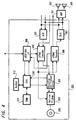
FIG. 4 is a block diagram showing a configuration
example of the MD device 300. The MD device 300 serving as an
audio recording and playback device is a device for recording
and reproducing an audio signal and so on as digital data by
using a magneto-optical disc or an optical disc housed in a
resin package and called MD (mini disc) as a recording medium.
-
As for the configuration of a recording system, an
analog audio signal of two channels inputted from the outside is
converted to digital audio data by an analog to digital
converter 301. The digital audio data thus obtained by the
conversion is supplied to an ATRAC encoder 302. Audio data
compressed in the ATRAC scheme is obtained by encoding. In the
case where digital audio data is directly inputted from the
outside, the inputted audio data is supplied directly to an
ATRAC encoder 302 without being passed via the analog to digital
converter 301. Data encoded by the encoder 302 is supplied to a
recording and playback section 303 and subjected to processing
for recording. On the basis of the data thus processed, an
optical pickup 304 is driven and data is recorded on a disc
(magneto-optical disc) 305. At the time of recording, magnetic
field modulation is conducted by a magnetic head which is not
illustrated.
-
As for the configuration of a playback system, data
recorded on a disc (magneto-optical disc or optical disc) 305 is
read out by the optical pickup 304, and subjected to playback
processing in the recording and playback section 303. Audio
data compressed in the ATRAC scheme is thus obtained. The
reproduced audio data is supplied to an ATRAC decoder 306 and
decoded to digital audio data of a predetermined scheme. The
decoded audio data is supplied to a digital to analog converter
307, converted to an analog audio signal of two channels, and
outputted. In the case where digital audio data is to be
outputted directly to the outside, audio data decoded by the
ATRAC decoder 306 is outputted directly without being passed via
the digital to analog converter 307. The example of FIG. 4 has
such a configuration that the output audio signal subjected to
analog conversion is supplied to an amplifier device 391 and
subjected to audio output processing such as amplification and
an audio output of two channels is emitted from connected
speakers 392 and 393.
-
The MD device 300 includes an interface section 308 for
connection to the bus of the IEEE 1394 scheme. The MD device
300 is formed in order that audio data supplied from the bus
side of the IEEE 1394 scheme to the interface section 308 may be
supplied to the recording and playback section 302 via the ATRAC
encoder 302 and recorded on the disc 305. Furthermore, the MD
device 300 is formed in order that audio data reproduced from
the disc 305 may be supplied from the recording and playback
section 302 to the interface section 308 via the ATRAC decoder
306 and sent out to the bus side of the IEEE 1394 scheme.
-
The recording processing and playback processing
conducted in the MD device 300 and the transmission processing
conducted via the interface section 308 are executed under the
control of a central control unit (CPU) 310. A memory 311
serving as a work RAM is connected to the CPU 310. Furthermore,
manual operation information from a manual operation panel 312
is supplied to the CPU 310. Action control corresponding to the
manual operation information is conducted. Furthermore, when
the interface section 308 received control data such as an AV/C
command described later via the bus of the IEEE 1394 scheme, the
data is supplied to the CPU 310 in order that the CPU 310 may
effect corresponding operation control.
-
A data transmission state on the bus 1 of the IEEE 1394
scheme connecting the devices 100, 200 and 300 to each other
will now be described.
-
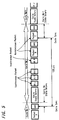
FIG. 5 is a diagram showing a cycle structure of data
transmission of devices connected by the IEEE 1394. According
to the IEEE 1394, data is divided into packets and the packets
are transmitted in a time division manner by taking a cycle
having a length of 125 µs as a reference. This cycle is
produced by a cycle start signal supplied from a node having a
cycle master function (some device connected to the bus).
Isochronous packets secure a band (which is called band although
it is a time unit) required for transmission from the head of
every cycle. In isochronous transmission, therefore,
transmission of data in a fixed time is ensured. However,
acknowledgment from the receiving side is not conducted. If a
transmission error occurs, there is no mechanism for protection
and data is lost. During time of each cycle which is not used
for isochronous transmission, a node which has secured the bus
as a result of arbitration sends out asynchronous packets. In
this asynchronous transmission, reliable transmission is ensured
by using acknowledgment and retry. However, the transmission
timing does not become fixed.
-
In order that a predetermined node may conduct
isochronous transmission, the node must correspond to the
jsochronous function. In addition, at least one of nodes
corresponding to the isochronous function must have a cycle
master function. In addition, at least one of nodes connected
to the IEEE 1394 serial bus must have an isochronous resource
manager function.
-
The IEEE 1394 conforms to a CSR (Control & Status
Register) architecture having an address space of 64 bits
prescribed by ISO/IEC 13213. FIG. 6 is a diagram showing the
structure of the address space of the CSR architecture. Sixteen
high-order bits are used for a node ID indicating each node on
the IEEE 1394. Forty-eight remaining bits are used to specify
an address space given to each node. The sixteen high-order
bits are further divided into ten bits of a bus ID and six bits
of a physical ID (a node ID of a narrow sense). A value having
1 in every bit is used for special purpose. Therefore, 1023
buses and 63 nodes can be specified. Upon bus reset, the node
IDs are provided again. The bus reset occurs when the
configuration of the devices connected to the bus 1 has changed.
For example, when it is recognized that any of the devices
connected to the bus 1 is removed or a device is newly connected
to the bus 1, bus reset is executed.
-
In an address space of 256 tera bytes prescribed by
forty-eight low-order bits, a space prescribed by twenty high-order
bits is divided into an initial register space of 2,048
bytes to be used for registers specific to CSR and registers
specific to the IEEE 1394, a private space, and an initial
memory space. In the case where the space prescribed by twenty
high-order bits is the initial register space, it is used as
configuration ROMs (read only memories), an initial unit space
to be used for application specific to the node, and plug
control registers (PCRs).
-
FIG. 7 is a diagram showing offset addresses, names, and
functions of principal CSRs. Offset of FIG. 7 denotes an offset
address compared with an address FFFFF0000000h where the initial
register space begins. (Numerals having h at their end are
expressed by hexadecimal notation.) A bandwidth available
register having an offset 220h indicates a band which can be
assigned to isochronous communication, and only the value of the
node operating as the isochronous resource manager is made
valid. That is, each node has CSRs shown in FIG. 6. As for the
bandwidth available register, however, only that of the
isochronous resource manager is made valid. In other words,
substantially only the isochronous resource manager has the
bandwidth available register. The bandwidth available register
holds a maximum value when no bands are assigned to isochronous
communication. Every time a band is assigned, the value is
decreased.
-
In channel available registers of offsets 224h to 228h,
respective bits correspond to channel numbers 0 to 63,
respectively. If a bit is 0, it is indicated that the channel
has already been assigned. Only the channel available register
of the node serving as the isochronous resource manager is
valid.
-
Referring back to FIG. 6, a configuration ROM based upon
a general ROM (read only memory) format is arranged in addresses
200h to 400h in the initial register space. In the
configuration ROM, a bus info-block, a route directory, and a
unit directory are arranged. In a company ID in the bus info-block,
an ID number indicating a manufacturer of the device is
stored. In a chip ID, there is stored an ID which is unique to
the device and the one and only in the world and which does not
have duplication with other devices.
-
In order to control the input and output of a device via
an interface, each node has a PCR (plug control register)
prescribed in IEC 1883, in addresses 900h to 9FFh in the initial
unit space of FIG. 6. This has been obtained by
substantializing the concept of a plug in order to logically
form a signal path similar to an analog interface. FIG. 8 is a
diagram showing a configuration of the PCR. The PCR has an oPCR
(output Plug Control Register) representing an output plug and
an iPCR (input Plug Control Register) representing an input
plug. Furthermore, each PCR has a register oMPR (output Master
Plug Register) and a register iMPR (input Master Plug Register)
respectively indicating information of an output plug or an
input plug specific to the device. Each device does not have a
plurality of oMPRs and iMPRs. However, each device is able to
have a plurality of oPCRs and iPCRs corresponding to individual
plugs, according to the capability thereof. Each of PCRs shown
in FIG. 8 has 31 oPCRs and 31 iPCRs. The flow of isochronous
data is controlled by operating registers corresponding to these
plugs.
-
FIG. 9 is a diagram showing configurations of the oMPR,
oPCR, iMPR and iPCR. FIG. 9A shows a configuration of the oMPR.
FIG. 9B shows a configuration of the oPCR. FIG. 9C shows a
configuration of the iMPR. FIG. 9D shows a configuration of the
iPCR. In a 2-bit "data rate capability" of the MSB side of each
of the oMPR and iMPR, there is stored a code indicating a
maximum transmission rate of isochronous data which can be
transmitted or received by the device. A broadcast channel base.
of the oMPR prescribes the number of a channel to be used for
broadcast output.
-
In a 5-bit "number of output plugs" of the LSB side of
the oMPR, there is stored the number of output plugs the device
has, i.e., a value indicating the number of oPCRS. In a 5-bit
"number of input plugs" of the LSB side of each iMPR, there is
stored the number of input plugs the device has, i.e., a value
indicating the number of iPCRs. A main extended field and a
subsidiary extended field are areas defined for future
extension.
-
An "on-line" of an MSB of each of the oPCRs and iPCRs
indicates the usage state of the plug. In other words, the on-line
value having "1" indicates that the plug is on-line and the
on-line value having "0" indicates that the plug is off-line. A
value of a "broadcast connection counter" of each of oPCRs and
iPCRs indicates whether there is broadcast connection (1) or not
(0). A value of a "point-to-point connection counter" having a
6-bit width in each of oPCRs and iPCRs represents the number of
point-to-point connections the plug has. The point-to-point
connection (so-called p-p connection) is a connection for
conducting transmission only between one specific node and
another specific node.
-
A value of a "channel number" having a 6-bit width in
each of oPCRs and iPCRs represents the number of isochronous
channel to which the plug is connected. A value of a "data
rate" having a 2-bit width in each of oPCRs indicates the actual
transmission rate of a packet of isochronous data outputted from
that plug. A code stored in an "overhead ID" having a 4-bit
width in each of oPCRs indicates the bandwidth of the overhead
of the isochronous communication. A value of a "payload" having
a 10-bit width in each of oPCRs indicates a maximum value of
data contained in an isochronous packet the plug can handle.
-
FIG. 10 is a diagram showing relations among plugs, plug
control registers, and isochronous channels. In FIG. 10,
devices connected to a bus of the IEEE 1394 scheme are shown as
AV devices 71 to 73. Isochronous data specified in channel by
an oPCR [1] among oPCR [0] to oPCR [2] prescribed in
transmission rate and the number of oPCRs by an oMPR of the AV
device 73 is sent out to a channel #1 of an IEEE 1394 serial
bus. Between iPCR [0] and iPCR [1] prescribed in transmission
rate and the number of iPCRs by an iMPR of the AV device 71, the
transmission rate and the iPCR [0] specify the input channel #1.
The AV device 71 reads isochronous data sent out on the channel
#1 of the IEEE 1394 serial bus. In the same way, the AV device
72 sends out isochronous data onto the channel #2 specified by
the oPCR [0]. The AV device 71 reads isochronous data from the
channel #2 specified by the iPCR [1].
-
In this way, data transmission is conducted between
devices connected by the IEEE 1394 serial bus. In the system of
the present example, however, control and state decision of
respective devices can be conducted by utilizing an AV/C command
set prescribed as commands for controlling devices connected via
the IEEE 1394 serial bus. The AV/C command set will now be
described.
-
First of all, a data structure of a subunit identifier
descriptor in the AV/C command set used in the system of the
present example will now be described by referring to FIGS. 1 to
14. FIG. 11 shows the data structure of the subunit identifier
descriptor. As shown in FIG. 11, the subunit identifier
descriptor is formed of lists each having a hierarchical
structure. In the case of a tuner, the lists represent
channels. In the case of a disc, the lists represent songs
recorded thereon. A list of the highest layer of a hierarchical
structure is called root list. For example, a list 0 becomes a
root for its subordinate lists. In the same way, other lists
become root lists. There are as many root lists as objects.
For example, in the case where AV devices connected to the bus
are tuners, objects are channels in digital broadcast.
Furthermore, all lists of one hierarchical class share common
information.
-
FIG. 12 shows a format of a general subunit identifier
descriptor. In the general subunit identifier descriptor,
attribute information concerning the function is described as
its contents. A "descriptor length field" does not contain the
value of its field itself. A "generation ID" indicates the
version of the AV/C command set. Its value is, for example,
"00h" (where h represents hexadecimal notation). As shown in
FIG. 13, for example, "00h" means that the data structure and
command conform to version 3.0 of the AV/C General
Specification. Furthermore, as shown in FIG. 13, all values
except "00h" are reserved and secured for future specifications.
-
A "size of list ID" indicates the number of bytes of a
list ID. A "size of object ID" indicates the number of bytes of
an object ID. A "size of object position" indicates the
position (the number of bytes) in a list to be used for
reference at the time of control. A "number of root object
list" indicates the number of root object lists. A "root object
list ID" indicates an ID for identifying a root object list of
the highest rank of each of independent hierarchical classes.
-
A "subunit dependent length" indicates the number of
bytes of a subsequent "subunit dependent information" field.
The "subunit dependent information" field is a field indicating
information peculiar to the function. A "manufacturer dependent
length" indicates the number of bytes of a subsequent "
manufacturer dependent information" field. The "manufacturer
dependent information" field is a field indicating specification
information of a vendor (manufacturer). If the descriptor does
not contain "manufacturer dependent information", the "
manufacturer dependent information" field is not present.
-
FIG. 14 indicates the assignment range of list IDs shown
in FIG. 12. As shown in FIG. 14, "0000h to 0FFFh" and "4000h to
FFFFh" are reserved and secured as assignment ranges for future
specifications. In order to identify dependent information of
the function type, "1000h to 3FFFh" and "10000h to maximum value
of list ID" are prepared.
-
By referring to FIGS. 15 to 20, the AV/C command set
used in the system of the present example will now be described.
FIG. 15 shows a stack model of the AV/C command set. As shown
in FIG. 15, a physical layer 81, a link layer 82, a transaction
layer 83, and a serial bus management 84 conform to the IEEE
1394. A FCP (Function Control Protocol) 85 conforms to IEC
61883. An AV/C command set 86 conforms to 1394 TA
specifications.
-
FIG. 16 is a diagram showing a command and a response of
the FCP 85 shown in FIG. 15. The FCP is a protocol for
effecting control of devices (nodes) on the bus of the IEEE 1394
scheme. As shown in FIG. 16, the controlling side is a
controller and the controlled side is a target. Command and
response transmission of the FCP are conducted between nodes by
using write transaction of asynchronous communication of the
IEEE 1394. Upon receiving data, the target returns an
acknowledge to the controller for acknowledging the reception.
-
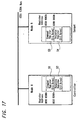
FIG. 17 is a diagram showing the relation between the
command and response of the FCP of FIG. 16 in more detail. A
node A and a node B are connected via an IEEE 1394 bus. The
node A is the controller, and the node B is the target. In both
the node A and the node B, a command register and a response
register each having 512 bytes are prepared. As shown in FIG.
17, the controller conveys an instruction by writing a command
message into a command register 93 of the target. On the other
hand, the target conveys a response by writing a response
message into a response register 92 of the controller. For the
two messages, control information is exchanged. The kind of a
command set sent by the FCP is described in CTS included in a
data field shown in FIG. 18 and described later.
-
FIG. 18 shows a data structure of a packet transmitted
in an asynchronous transfer mode of the AV/C command. The AV/C
command set is a command set for controlling an AV device, and
its CTS (ID of command set) = "0000". AV/C command frames and
response frames are exchanged between the nodes by using the
above described FCP. In order to prevent casting a burden upon
the bus and the AV device, a response to a command is defined to
be sent within 100 ms. As shown in FIG. 18, data of an
asynchronous packet has 32 bits (= 1 quadlet) in the horizontal
direction. Upper columns of FIG. 18 show a header portion of
the packet, and lower columns of FIG. 18 show a data block. A
destination ID indicates the destination.
-
The CTS indicates an ID of the command set. In the ÀV/C
command set, CTS = "0000". A C type/response field indicates a
function class of a command when the packet is a command, and a
processing result of a command when the packet is a response.
Commands are broadly divided into four kinds: (1) commands
(CONTROL) for controlling the function from the outside; (2)
commands (STATUS) for inquiring about the state from the
outside; (3) commands for inquiring whether support of a control
command is present, from the outside (GENERAL INQUIRY (whether
support of an opcode is present) and SPECIFIC INQUIRY (whether
support of an opcode and operands are present)); and (4)
commands (NOTIFY) for requesting the notice of a state change to
the outside.
-
A response is returned according to the command kind.
As responses to the CONTROL commands, there are "NOT
IMPLEMENTED", "ACCEPTED", "REJECTED" and "INTERIM". AS
responses to the STATUS commands, there are "NOT IMPLEMENTED",
"REJECTED", "IN TRANSACTION", and "STABLE". As responses to the
commands for inquiring whether support of a command is present,
from the outside (GENERAL INQUIRY and SPECIFIC INQUIRY), there
are "IMPLEMENTED" and "NOT IMPLEMENTED". As responses to the
commands for requesting the notice of a state change to the
outside, there are "NOT IMPLEMENTED", "REJECTED", "INTERIM", and
"CHANGED".
-
A "subunit type" is provided to specify a function in
the device. For example, "tape recorder/player", "tuner", or
the like is assigned. Besides the function corresponding to the
device, BBS (bulletin board subunit) which is a subunit opening
information to other devices is also assigned to the "subunit
type". In order to distinguish in the case where there are a
plurality of subunits of the same kind, addressing is conducted
by using a subunit ID as a distinguishing number. An "opcode"
which is a code of operation represents a command. An "operand"
represents a parameter of the command. Additional operands
which are added as occasion demands are also prepared. After
the operands, "0" data or the like are added. A Data CRC
(Cyclic Redundancy Check) is used for error check at the time of
data transmission.
-
FIG. 19 shows a concrete example of the AV/C command.
The left side of FIG. 19 shows concrete examples of c type/response.
Its upper column shows commands and its lower column
shows responses. "CONTROL" is assigned to "0000". "STATUS" is
assigned to "0001". "SPECIFIC INQUIRY" is assigned to "0010".
"NOTIFY" is assigned to "0011". "GENERAL INQUIRY" is assigned
to "0100". "0101 to 0111" are reserved and secured for future
specifications. "NOT IMPLEMENTED" is assigned to "1000".
"ACCEPTED" is assigned to "1001". "REJECTED" is assigned to
"1010" "IN TRANSITION" is assigned to "1011" "IMPLEMENTED/STABLE"
is assigned to "1100". "CHANGED" is assigned to "1101".
"INTERIM" is assigned to "1111". "1110" is reserved and secured
for future specifications.
-
The center of FIG. 19 shows concrete examples of the
subunit type. "Video monitor" is assigned to "00000". "Disc
recorder/player" is assigned to "00011". "Tape recorder/player"
is assigned to "00100". "Tuner" is assigned to "00101". "Video
camera" is assigned to "00111". A subunit called BBS (Bulletin
Board Subunit) and used as a bulletin board is assigned to
"01010". A manufacturer dependent subunit type (Vender unique)
is assigned to "11100". A specific subunit type (Subunit type
extended to next byte) is assigned to "11110". "Unit" is
assigned to "11111", and it is used when the command or response
is sent to the device itself. For example, turning on and off
of the power supply can be mentioned.
-
The right side of FIG. 19 shows concrete examples of
opcodes (operation codes). For each of the subunit types, a
table of opcodes exists. In FIG. 19, opcodes in the case where
the subunit type is the "tape recorder/player" are shown.
Furthermore, for each opcode, an operand is defined. Here, a
manufacturer dependent value (Vender dependent) is assigned to
"00h". "Search mode" is assigned to "50h". "Time code" is
assigned to "51h". "ATN" is assigned to "52h". "Open memory"
is assigned to "60h". "Memory reading" is assigned to "61h".
"Memory writing" is assigned to "62h". "Loading" is assigned to
"C1h". "Audio recording" is assigned to "C2h". "Reproducing"
is assigned to "C3h". "Rewinding" is assigned to "C4h".
-
FIG. 20 shows concrete examples of an AV/C command and
an AV/C response. For example, in the case where a playback
order is to be given to a playback device serving as the target
(consumer), the controller sends the command as shown in FIG.
20A to the target. In this command, CTS = "0000" because the
AV/C command set is used. Since the command (CONTROL) for
controlling a device from the outside is used, the c type
becomes c type = "0000" (see FIG. 19). Since the subunit type
is a tape recorder/player, it follows that subunit type =
"00100" (see FIG. 19). Furthermore, "id" indicates the case of
ID0, and id = 000. The opcode becomes "C3h" meaning the
playback (see FIG. 19). The operand becomes "75h" meaning the
forward direction (FORWARD). Upon playback, the target returns
a response as shown in FIG. 20B to the controller. Since
"accepted" is included in the response, it follows that response
= "1001" (see FIG. 19). Except the response, other fields are
the same as those of FIG. 20A, and description thereof will be
omitted.
-
It is now assumed that data transmission based upon the
AV/C command is conducted in the system of the present example
heretofore described. Processing of recognizing a device
connected to the bus 1 will now be described.
-
First, in the network system formed by connecting
devices with the bus 1 of the IEEE 1394 scheme, each device has
an individual node unique ID as already described. Apart from
the node unique ID, a node ID is set within the network. Upon
bus reset, the node ID is set individually for the device of
each node unique ID.
-
If there is bus reset, in the case of the present
example, the controller 13 in the IRD 100 conducts processing of
discriminating the kinds of other devices connected to the bus 1
(the DVCR 200 and the MD device 300) by using a command and a
descriptor prescribed in the AV/C command. Hereafter, the
processing of discriminating the kind of the connected device
will be described by referring to flow charts of FIGS. 21 and 22
and data configurations of FIG. 23 and subsequent drawing.
-
First, as shown in the flow chart of FIG. 21, the
controller 13 in the IRD 100 determines whether bus reset
processing of resetting the node unique ID and so on of the bus
1 has been conducted (step S11). Upon judging the bus reset to
have been conducted, the controller 13 transmits a SUBUNIT INFO
command prescribed in AV/C successively to devices connected to
the bus 1 (step S12). Details of the SUBUNIT INFO command will
be described later. The SUBUNIT INFO command is a command that
devices corresponding to AV/C need to have. When there is a
correct answer to this Command, the device of the opposite party
is known to be a device corresponding to the AV/C.
-
After the controller 13 in the IRD 100 has transmitted
the SUBUNIT INFO command, the controller 13 determines whether
answer data prescribed in AV/C has been returned to the IRD 100
(step S13). If answer data is not transmitted, the controller
13 judges discrimination of the pertinent device using the AV/C
command to be impossible (step S27).
-
When answer data is transmitted at step S13, the
controller 13 judges the subunit type indicated by the answer
data (step S14). Details of the subunit type which can be
discriminated will be described later. In the AV/C, however, it
is possible to discriminate at least a unit (device) of such a
type that a disc is handled as the medium, a unit (device) of
such a type that tape (magnetic tape) is handled as the medium,
and a unit (device) of another type.
-
If in decision of step S14 in the controller 13 it is
judged that the subunit that the unit of the opposite party of
communication has is a subunit of such a type that a disc is
handled as the medium, then the controller 13 conducts
processing of reading out a descriptor that the opposite party
has. In order to read out the descriptor, the controller 13
first transmits a command of OPEN descriptor control which is a
command for opening the descriptor of the pertinent unit (step
S15).
-
The controller 13 then determines whether there is a
return from the pertinent device, for the transmission of the
command (step S16). If there is a return, the controller 13
transmits a command of READ descriptor control which is a
command for reading out the opened descriptor (step S17).
-
Furthermore, the controller 13 determines whether there
is a return from the pertinent device, for the transmission of
the command (step S18). If there is a return, the controller 13
judges contents of data of the medium type included in data of
the returned descriptor, and determines whether the code has a
medium type of MD (mini disc) (step S19). Upon judging the code
to be an MD code, the controller 13 of the IRD 100 recognizes
the pertinent device as an MD device (step S20). If there is no
return command at the step S16 or S18, or if the medium type is
judged not to be MD at the step S19, the controller 13
recognizes the pertinent device as a disc device handling a disc
of another format (step S21).
-
If the subunit the unit of the opposite party of the
communication has is judged at the step S14 in the controller 13
to be one of the type handling tape as its medium, then the
controller 13 conducts processing of inquiring about the format
used by the opposite party to play back the tape. In other
words, the controller 13 transmits a status command of a TAPE
PLAYBACK FORMAT for inquiring about the tape playback format on
the bus 1 (step S22).
-
And the controller 13 determines whether there is a
return from the pertinent device for the transmission of the
command (step S23). If there is a return, the controller 13
determines whether the inquiry about the tape playback format is
valid. To be concrete, the controller 13 determines whether the
return is a response other than the response "NOT IMPLEMENTED"
which is a response being not able to respond to the
transmission of a status command conducted at the step S22 (step
S24).
-
When the controller 13 has judged the response to be a
command other than "NOT IMPLEMENTED", the controller 13
recognizes the pertinent unit as a DVCR of the D-VHS standards
(step S25). If there is no answer command at the step S23, or
if the response is judged to be a command of "NOT IMPLEMENTED"
at the step 24, the controller 13 recognizes the device as a
tape device which handles tape of a different format (step S26).
-
Furthermore, if in the decision of the subunit type at
the step S14 the subunit type is judged to be other than a disc
and tape, the controller 13 recognizes the device as a device of
a different type (step S28).
-
The IRD 100 executes the processing heretofore described
successively for respective devices connected to the bus 1,
discriminates the kinds and so on of all devices connected to
the bus 1, and stores and holds the data thus discriminated in a
storage section prepared in the controller 13. After the IRD
has thus discriminated the kinds and so on of respective
devices, the IRD 10 collects data concerning respective devices.
-
By referring to a flow chart of FIG. 22, processing of
collecting data concerning respective discriminated devices
executed in the controller 13 of the IRD 100 will now be
described.
-
First, it is determined whether there is a change in the
network topology (step S31). Here, the network topology is
judged to have changed when the bus resetting is conducted and
thereafter the processing of discriminating the kinds of
respective devices is conducted (i.e., the processing of the
flow chart of FIG. 21 is executed). If the network is judged to
have changed, then the controller 13 sends a command for
inquiring predetermined data peculiar to all devices connected
to the bus 1 included in the network, which are node unique IDs
here, of respective devices. The controller 13 of the IRD 100
judges responses for the command, and judges the node unique IDs
of respective devices (step S32). By the way, if the node
unique IDs of respective devices in the network have already
been acquired by, for example, the processing of the flow chart
of FIG. 21, the controller 13 reads out the acquired and stored
node unique IDs and judges them.
-
Here, the controller 13 determines whether data
concerning devices in the network configuration preceding the
detection of the network topology change conducted at the step
S31 are held in the storage section prepared in the controller
13 (step S33). If in this decision the previous device data are
judged not to have been held, then the controller 13 sends a
command successively to all devices on the network to make them
transmit data concerning the devices, and conducts processing
for storing data returned in response to the command in the
storage section prepared in the controller 13 (step S34). The
processing conducted at the step S34 is ordinary device
information acquisition processing conventionally conducted.
-
If in the decision of the step S33 the previous device
data are judged to have been held, the controller 13 determines
whether there is a device having an ID which is included in the
node unique IDs of respective devices judged at the step S32 and
which is different from the node unique ID of the device stored
in the storage section (step S35). If in this decision a device
having a node unique ID different from the stored ID is judged
to be present, the controller 13 sends a command to the device
having the pertinent node unique ID to make the device send data
concerning the device, and conducts processing for storing data
returned in response to the command in the storage section
prepared in the controller 13 (step S36).
-
Upon conducting the processing heretofore described, the
controller 13 causes only data concerning the devices currently
connected to the network to be held and other data to be
deleted, and thus causes the latest network data to be held
(step S37). In other words, if the information acquisition
processing is conducted at the step S34, the controller 13
causes all acquired data to be held as the network data. If a
device different from any of the devices data of which are held
is judged at the step S35 not to be present, the controller 13
causes the previously stored data to be held as they are as the
network data. (If a device previously connected disappears,
however, the controller 13 causes the data concerning the device
to be deleted.) If the presence of a differing device is
detected at the step S35 and if data of some devices are
acquired at the step S36, then the controller 13 causes network
data updated with the acquired data to be held.
-
By the way, the node unique IDs used as data peculiar to
respective devices in the processing heretofore described are
identification data respectively provided to the devices
connected to the bus 1 of the IEEE 1394 scheme, one by one. For
example, as shown in FIG. 23, the node unique ID of each device
is formed of a predetermined number of bits. From data of a
predetermined number of bits in the data, the device type of the
device (representing which type the device belongs to) and the
vendor name such as the manufacturing company name of the device
can be known. In addition, data corresponding to a serial code
such as a manufacturing number of each device is also inserted.
Even if devices have the same form and are manufactured by the
same company, their node unique IDs become data of different
values. A node unique ID as shown in FIG. 23 is stored in the
storage section in the controller 13 of the IRD 100 so as to be
associated with, for example, each node ID. (Since the node ID
is re-provided at the time of, for example, bus resetting, it is
not necessarily constant at all times.)
-
In this way, processing of collecting data from
respective devices connected to the network is conducted. In
the case where at least device data before bus resetting remain
and only some devices differ between the network before bus
resetting and the current network, therefore, it is necessary to
collect only data concerning the differing devices. The
processing quantity for collecting the device data on the
network is thus reduced. The burden of data collection can be
reduced. In addition, the time required for collection of the
device data can be shortened.
-
For example, it is assumed in the case of the network
configuration shown in FIG. 1 and already described that the MD
device 400 is newly connected to the bus 1 and bus resetting is
applied. Only data concerning the MD device 400 does not exist
in the storage section of the controller 13 of the IRD 100.
Data of other devices 200 and 300 are already stored therein.
Therefore, it is necessary to only request the controller 41 of
the MD device 400 to transmit data concerning the device 400.
As compared with the case where all devices are requested to
transmit data, the processing quantity and the processing time
required for updating the network data can be substantially
reduced.
-
Furthermore, in the case where some devices are removed
from the bus 1 and thereby bus resetting is applied, it is
necessary to only delete data concerning the removed devices.
In the same way, therefore, new network data are obtained by
simple processing.
-
The subunit info status command in the AV/C command is
defined by a format shown in FIG. 24. In FIG. 24, eight bits
are shown as one unit (a line illustrated in the lateral
direction). (This also holds true in format diagrams of FIG. 25
and subsequent drawing.) The subunit info response in the AV/C
command is defined by a format shown in FIG. 25. Data of
opcodes and operands shown in FIGS. 24 and 25 are disposed in
the fields of the opcode and operands in the FCP frame included
in the packet shown in FIG. 18. In the subunit info status
command shown in FIG. 24, subunit info data is disposed as the
opcode. Data of a page and an extension code are disposed in an
area of an operand [0]. In an area of an operand [1] and
subsequent operands, a specific value (here FF) is disposed. In
the response for this command, page data is disposed in an area
of an operand [1] and subsequent operands as shown in FIG. 25.
Areas of the opcode and an operand [0] of the response are the
same as those of the command.
-
In the example of the flow chart of FIG. 21, the subunit
type is inquired to judge the kind of the device. However, the
unit type may be inquired. A unit info status command for
inquiring about the unit type is defined by a format shown in
FIG. 26. A unit info response serving as its answer is defined
by a format shown in FIG. 27. In the unit info status command
shown in FIG. 26, unit info data is disposed as the opcode. In
an area of an operand [0] and subsequent operands, a specific
value (here FF) is disposed. In the response for this command,
data of the unit type and the unit are disposed in an area of an
operand [1] as shown in FIG. 27. Furthermore, in operands [2]
to [4], a company ID which is a code provided to each company
which has manufactured each device (unit) is disposed.
-
Some of codes concerning the subunit type prescribed in
the AV/C command are shown in FIG. 28. FIG. 28 shows some of
the subunit types already shown in FIG. 19, again. Here, video
monitor, disc recorder and/or player, tape recorder and/or
player, tuner, video camera, and so on are prescribed as subunit
types. Furthermore, a subunit type having a special format
prescribed for each company is prescribed as a vendor unique
value. By judging the data of this subunit type, the controller
13 of the IRD 100 can decide the type of the subunit the device
of the opposite party has.
-
In the case of the AV/C command, a command for opening
the descriptor (open descriptor command) required after a
decision of the subunit type has been made if the decided type
is "disc" is prescribed in a format shown in FIG. 29. In this
open descriptor command, data indicating an open descriptor is
disposed as the opcode, and data for descriptor identification
and data of subfunction are disposed as the operands. In the
case of the ÀV/C command, a command for reading out the
descriptor (read descriptor command) after the descriptor has
been opened by the open descriptor command is prescribed in a
format shown in FIG. 30. In this read descriptor command, data
indicating a read descriptor is disposed as the opcode, and data
for descriptor identification, data of read result status, data
length, and data of read address are disposed as the operands.
-
FIG. 31 is a diagram showing a configuration example of
a descriptor of a disc type subunit in the AV/C command read out
by the above described command. The descriptor has data of a
hierarchical structure. An example of a disc subunit identifier
descriptor is shown in FIG. 31. For example, a descriptor
length, a generation ID, a size of a list ID, a size of an
object ID, a size of an object position, the number of root
object lists, a root object list ID, a data length of data
unique to the disc subunit, information unique to the disc
subunit, a data length of data unique to a manufacturing maker,
and information unique to the manufacturing maker are disposed.
As for the root object list IDs, as many root object list IDs as
indicated by the data of the number of root object lists are
disposed.
-
As for data of disc subunit dependent information which
is information unique to a disk subunit contained in the disk
subunit identifier descriptor, it has a configuration shown in
FIG. 32. An address offset shown in FIG. 32 is an offset value
of an address from an operand in which the head portion of the
data of the disc subunit dependent information is disposed. As
the information, a data length of an information field unique to
the disk subunit, an attribute, a version of the disk subunit,
the number of supported medium types, and data of supported
medium type are disposed. As for the data of supported medium
type, as many data of supported medium type as indicated by the
number of supported medium types are disposed. In the data of
supported medium type, details of the medium format are
indicated. In the case of the present example, it is known from
the data that the device is a disc device which uses a disc
having a format of an MD (mini disc) as the medium.
-
Furthermore, a format of a data structure of a status
command having a TAPE PLAYBACK FORMAT for inquiring the tape
playback format required after the decision of the subunit type
if the decided type is tape is shown in FIG. 33. In this
command, data of the tape playback format is disposed in the
opcode, and a specific value (here FF) is disposed in the
operands.
-
And the format of a response for this status command is
shown in FIG. 34. In this response, a medium type and data of
format parameters are disposed in the area of the operands. The
response at this time is indicated by one of response types
already shown in FIG. 19. To be concrete, a response for a
status command in the AV/C command is one of "NOT IMPLEMENTED",
"REJECTED", "IN TRANSACTION", and "STABLE".
-
In the case of a DVCR having a format of a D-VHS
corresponding to the AV/C command, the response does not become
"NOT IMPLEMENTED" which is a response disabling the answer to
transmission of the status command. Depending on the device
state at that time, the response becomes one of "REJECTED", "IN
TRANSITION", and "STABLE". By judging the response to be other
than "NOT IMPLEMENTED", the device is known to be a DVCR having
a format of the D-VHS. In the case of a tape device of a
different format (such as a DVCR called DV standard), a status
command of the TAPE PLAYBACK FORMAT is not implemented in the
AV/C command, and consequently the response becomes "NOT
IMPLEMENTED" for which answering is impossible.
-
When a network system has been formed by connecting
devices controlled by the AV/C command to the bus 1, it is
possible to know details of the kinds, such as types and medium
formats, of the devices, without previously knowing which
protocols the devices connected to the network correspond to, by
conducting the processing described heretofore with reference to
the present embodiment. It becomes possible to execute
functions which can be executed only for devices having specific
medium formats connected to the network, without user's
operation of setting the device type and so on
-
After the kinds and so on of the devices have been
judged, it is necessary in some cases to collect detailed data
concerning the devices. If altered devices are judged to exist
in those devices by comparison with previously stored data, then
only data concerning the altered devices are read out. As a
result, the burden and the processing tune required to collect
data concerning the devices connected to the network can be
reduced.
-
In the above described embodiment, the subunit type is
first inquired by using the subunit info command, in order to
determine whether a device connected to the network corresponds
to the AV/C command. However, the protocol and command set used
by the device connected to the network may be ascertained by
different processing.
-
For example, it may be determined from the data of the
configuration ROM a node (unit) connected to the network has
whether the device corresponds to the AV/C command. In other
words, data concerning the unit attribute of the configuration
ROM prescribed by, for example, IEEE 1212 has a data
configuration of a format shown in FIG. 33. By a combination of
data of unit spec id and data of unit sw version included in the
data concerning the unit attribute, the corresponding protocol
and command set are determined as shown in FIG. 34. To be
concrete, it is known from these data which of, for example, the
standard of AV/C command standardized by 1394TA, standard of
common application language (CAL) standardized by 1394TA,
standard of Europe home system (EHS) standardized by 1394TA, and
standard of ANSI the protocol and command set conform to. When
it is known from the correspondence between data of the unit ID
and data of the unit SW version that the protocol and command
set correspond to the AV/C command, details of the unit may be
inquired.
-
Furthermore, after judging the protocol and command set
to correspond to the AV/C command from the correspondence shown
in FIG. 34, the processing of the step S12 and subsequent steps
of the flow chart shown in FIG. 21, i.e., the processing of
sending the status command of the subunit and subsequent
processing may be executed.
-
Furthermore, in the case where it is determined from
different data whether the connected device corresponds to the
AV/C command and in the decision the connected device is judged
to correspond to the AV/C command, the detailed subunit type and
medium format may be inquired. For example, as shown in FIG.
35, a code value of the CTS command is determined . It may be
determined whether the connected device corresponds to the AV/C
command on the basis of the code value of the CTS command. The
code value of the CTS command is disposed in a four-bit section
(a portion represented as 0000) located at head of a FCP frame
shown in FIG. 18. In this case, when the code value of the CTS
command is "0000", it is known that the connected device
corresponds to the AV/C command.
-
Furthermore, each data of the configuration ROM
prescribed by the IEEE 1212 is provided with a key ID as shown
in FIG. 36. By reading the data of the model ID included in the
key ID, details such as the type of the device may be judged
directly.
-
Furthermore, in the above described embodiment, the
processing is conducted when the IRD 100 connected to the bus 1
collects data of devices included in the network formed by the
bus 1. As a matter of course, however, the present invention
may also be applied to the case where any device collects data
in the network.
-
Furthermore, in the above described embodiment, the
device kind discrimination processing shown in the flow chart of
FIG. 21 is conducted and thereafter the device data collection
processing shown in the flow chart of FIG. 22 is conducted. Not
after the device kind discrimination processing is conducted,
but when data specifying the device connected to the network
(such as the node unique ID) is detected, the device data
collection processing shown in the flow chart of FIG. 22 may be
conducted.
-
Furthermore, in the above described embodiment, the case
of the network formed by the bus of the IEEE 1394 scheme has
been described. However, the present invention can also be
applied to the case where data concerning devices are collected
in a different network configuration.