EP1098124A1 - Klappenventil mit einer Betätigungsvorrichtung - Google Patents
Klappenventil mit einer Betätigungsvorrichtung Download PDFInfo
- Publication number
- EP1098124A1 EP1098124A1 EP00440293A EP00440293A EP1098124A1 EP 1098124 A1 EP1098124 A1 EP 1098124A1 EP 00440293 A EP00440293 A EP 00440293A EP 00440293 A EP00440293 A EP 00440293A EP 1098124 A1 EP1098124 A1 EP 1098124A1
- Authority
- EP
- European Patent Office
- Prior art keywords
- butterfly
- actuating rod
- butterfly valve
- housing
- rod
- Prior art date
- Legal status (The legal status is an assumption and is not a legal conclusion. Google has not performed a legal analysis and makes no representation as to the accuracy of the status listed.)
- Withdrawn
Links
Images


Classifications
-
- F—MECHANICAL ENGINEERING; LIGHTING; HEATING; WEAPONS; BLASTING
- F16—ENGINEERING ELEMENTS AND UNITS; GENERAL MEASURES FOR PRODUCING AND MAINTAINING EFFECTIVE FUNCTIONING OF MACHINES OR INSTALLATIONS; THERMAL INSULATION IN GENERAL
- F16K—VALVES; TAPS; COCKS; ACTUATING-FLOATS; DEVICES FOR VENTING OR AERATING
- F16K27/00—Construction of housing; Use of materials therefor
- F16K27/02—Construction of housing; Use of materials therefor of lift valves
- F16K27/0209—Check valves or pivoted valves
- F16K27/0218—Butterfly valves
-
- F—MECHANICAL ENGINEERING; LIGHTING; HEATING; WEAPONS; BLASTING
- F16—ENGINEERING ELEMENTS AND UNITS; GENERAL MEASURES FOR PRODUCING AND MAINTAINING EFFECTIVE FUNCTIONING OF MACHINES OR INSTALLATIONS; THERMAL INSULATION IN GENERAL
- F16K—VALVES; TAPS; COCKS; ACTUATING-FLOATS; DEVICES FOR VENTING OR AERATING
- F16K31/00—Actuating devices; Operating means; Releasing devices
- F16K31/12—Actuating devices; Operating means; Releasing devices actuated by fluid
- F16K31/16—Actuating devices; Operating means; Releasing devices actuated by fluid with a mechanism, other than pulling-or pushing-rod, between fluid motor and closure member
- F16K31/165—Actuating devices; Operating means; Releasing devices actuated by fluid with a mechanism, other than pulling-or pushing-rod, between fluid motor and closure member the fluid acting on a diaphragm
- F16K31/1655—Actuating devices; Operating means; Releasing devices actuated by fluid with a mechanism, other than pulling-or pushing-rod, between fluid motor and closure member the fluid acting on a diaphragm for rotating valves
Definitions
- the present invention relates to a butterfly valve provided with a device for control, said valve comprising a body through which a conduit for the passage of a fluid as well as a butterfly disposed in the duct and mounted pivoting around an axis of rotation so that the butterfly closes more or less completely the conduit according to its angular position, said device control comprising an actuating rod coupled to a control arranged to move it linearly in a guide hole formed in a side wall of the body, this actuating rod being coupled to said butterfly so that when the actuating rod is moved linearly, it rotates the butterfly about its axis of rotation.
- a control device for a butterfly valve
- a control device comprises an actuating rod rotary rigidly and coaxially linked to the butterfly.
- Rod rotation actuation causes the butterfly to rotate and therefore the opening or closing of the duct, according to the direction of rotation.
- This actuation rod rotating through the wall of the valve body and is coupled to a control of its rotation.
- means dynamic seals such as a rubbing O-ring, are required between the rotary actuating rod and the perforated wall of the body.
- the organ of control can be constituted by a handle, of the tap type, actuated by rotation manually. It can also include a rotary servomotor, such than a servo-driven rotary electric motor, in case the fluid flow in the valve duct must be adjusted precisely, continuously and so predefined according to determined parameters.
- the control member can also consist of an actuator pneumatic diaphragm as in publication EP-A-682,199.
- the pneumatic actuator is coupled to a transformation of a translational movement at the level of the rod actuation in a rotational movement at the level of the butterfly.
- the actuating rod is coupled at one of its ends to the membrane and has a transverse pin arranged at the other end to circulate in two helical grooves provided in a radial bore one-eyed butterfly. This radial bore has a depth which does not extend beyond of the throttle radius and the motion transmission forces between the rod and butterfly are concentrated at the ends of the pin.
- the rod actuation is guided in translation in a cylindrical bore of the body valve but is not locked in rotation. Only its connection with the membrane limits its rotational movement, which is clearly insufficient and risk damaging the membrane.
- the radial bore of the butterfly not being through, the actuating rod cannot play the role of axis of rotation for the butterfly. The latter is therefore guided in rotation by a span hemispherical provided in the body opposite the control member.
- the actuator to diaphragm is not integrated into the valve body but is arranged radially and at a distance from this body generating an annoying lateral bulk.
- the aim of the present invention is to resolve these drawbacks by providing a butterfly valve provided with a simplified control device, economical, compact, integrated into the valve, easy to assemble, reliable, including the chain kinematic allows a better distribution of forces and a precision of movement.
- a butterfly valve as defined in the preamble, characterized in that the butterfly has a central through bore provided with a threaded section extending over a length greater than the radius of said butterfly, in that the actuating rod extends over a length at least equal to the diameter of the butterfly and has a threaded section engaged with said threaded section of the butterfly, and in that said bore and said actuating rod are coaxial with the axis of rotation of the butterfly.
- the guide hole formed in the side wall of the body has a square section and the actuating rod has a section of square section in correspondence so that this rod actuator is guided in translation in said orifice and locked in rotation with respect to said body.
- the threads of the threaded section of the central bore and the outer section of the actuating rod comprise each several identical screw threads.
- the linear displacement of the actuating rod is limited between two extreme positions, and in that the stroke of the actuating rod between these two extreme positions corresponds to a 90 degree rotation of the butterfly respectively between a closed position, in which it completely closes the duct, and an open position, in which it opens the drove.
- the butterfly valve control device has a pneumatic actuator provided with an enclosure in which a mobile waterproof membrane rigidly linked to the actuating rod, this membrane hermetically dividing the enclosure into two chambers and being arranged to adopt a position inside the enclosure according to the pressure difference between the two chambers in order to control linear movement of said throttle actuating rod
- the control preferably includes a box closed on one side by a bottom and open on the other side by an opening, this housing being fixed to the valve body with the corresponding opening of the side wall of so that the housing defines with this side wall said enclosure and the periphery of the waterproof membrane being sandwiched between the flat side wall of the body and the end of the housing corresponding to the opening.
- One of the rooms can communicate with the conduit through a passage in the side wall and can be a reference chamber, and the other chamber can communicate with a source of control fluid through a passage formed in the housing and can be a control chamber.
- the controller includes a return spring arranged in one of the two chambers, this return spring being arranged to axially urge said actuating rod.
- the butterfly valve control device has a electric actuator provided with at least one induction coil mounted around a fixed cylinder head arranged to receive a movable core in translation, the movable core being coupled to said actuating rod, the assembly being housed in a case
- the case is advantageously mounted laterally on said body around a projecting part of said body, this projecting part comprising a housing coaxial with the axis of rotation of said butterfly, in extension of said guide hole and arranged to linearly guide said movable core.
- This movable core and actuating rod are preferably formed in one room.
- control device comprises a return spring arranged between said movable core and the bottom of said housing.
- control device can include a member for measuring the linear displacement of said rod actuation, this measuring member being mounted in said body opposite of said control device and being coupled to the free end of the rod actuation.
- This measuring device can include, for example, a linear potentiometer arranged to deliver a signal proportional to the linear displacement of said actuating rod.
- the butterfly valve 11 provided with a control 10 comprises a body 12 generally in shape cylindrical.
- a cylindrical conduit 13 is formed coaxially through the body 12 so that it opens on either side of it.
- This conduit 13 forms a passage to guide the flow of a fluid.
- a butterfly 14 having generally the shape of a disc is arranged in the duct 13, substantially in the middle of it.
- the butterfly 14 is pivotally mounted around an axis of rotation 15 fixed with respect to the body 12 and disposed substantially diametrically in the duct 13.
- This axis of rotation 15 is materialized, in this example, by a rod 15 'passing right through said conduit 13 and housed at its ends in said body 12.
- the butterfly 14 more or less closes the conduit 13 completely according to its angular position.
- the body 12 of the valve 11 further comprises a fixing flange lateral 16, approximately annular, for fixing the control device 10.
- This flange 16 is arranged around a side wall 17 of the body 12 in gaze of the butterfly 14, substantially perpendicular to the axis of rotation 15 of the butterfly 14.
- the control device 10 comprises a housing 18 of substantially shaped cylindrical, closed on the side opposite the valve 11 by a bottom 19 and open the other side, corresponding to the side wall 17, through an opening 20.
- the housing 18 comprises a fixing element such as an annular flange 21 disposed around the housing 18 in an area close to the opening 20. This flange 21 is fixed by means of fixing screws 22 for example to the flange of attachment 16 of the body 12.
- the outside diameter of the housing 18 is substantially equal to the inside diameter of the annular flange 16 so that the section end opening side of the housing 18 is positioned in the flange 16.
- the control device 10 comprises an actuating rod 23 of the butterfly 14 slidingly mounted through a through guide hole 24, of section square, formed in the center of the side wall 17.
- This square orifice 24 guides in linear displacement of the rod 23 which comprises for this purpose and in correspondence a square section section 25 and simultaneously blocks the rod 23 in rotation.
- the butterfly 14 and this actuating rod 23 are better represented by the figure 3.
- the butterfly 14 has a central through bore 26 provided with a section threaded 26 ', whose axis coincides with its axis of rotation 15. This threaded section 26 'extends over a length greater than the radius of the butterfly 14.
- the thread of this section 26 ′ has three internal screw threads for example, the pitch of which is relatively large.
- the actuating rod 23 extends over a length greater than the diameter of the butterfly 14 and has a threaded end section 27 complementary, comprising three external screw threads whose pitch is identical to that of the three internal screw threads in bore 26.
- This section threaded 27 is engaged with the threaded section 26 'of the butterfly 14 so that when the actuating rod 23 is moved linearly, it drives in rotation of the butterfly 14 around its axis 15.
- This mode of transmission of movement by thread over a length greater than the diameter of the butterfly 14 allows the forces to be distributed evenly to avoid breaking zones or blocking and makes possible the transmission of high torques.
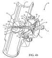
- the linear movement of the actuating rod 23 is limited between two extreme positions retract and exit so that the stroke of the rod 23 corresponds to a 90 degree rotation of the butterfly 14 respectively between its closed position, Figure 4a, and its open position, Figure 4b.
- the central through bore 26 of the butterfly 14 also includes a housing cylindrical 28 adapted to freely receive the square section section 25 of the actuating rod 23.
- This actuating rod 23 further comprises a through cylindrical guide hole 29 in which the rod 15 'is arranged of the butterfly 14 and whose internal diameter is slightly greater than the diameter outside of this rod 15 ′ in order to provide an operating clearance allowing a linear relative displacement between them.
- the actuating rod 23 is coupled to a control member 30 of its linear displacement between its two extreme positions inward and outward.
- this rod 23 has a cylindrical head 31, at its opposite end to the threaded end section 27, and an annular bead 32 disposed at its periphery between the square section 25 and the head 31.
- the end of the cylindrical hole 29 of rod 23 is threaded in an area approximately in correspondence of the head 31 and the bead 32.
- the control member 30 is consisting of a pneumatic actuator and comprises a membrane 33 having substantially the shape of a slightly curved disc whose outer diameter natural is substantially equal to the diameter of the side wall 17 of the body 12.
- This membrane 33 has a cylindrical central orifice 34 through which the head 31 of the actuating rod 23 whose outside diameter is substantially equal to the inside diameter of this orifice 34.
- the central area of the membrane 33 around the orifice 34 is fixed against the bead 32 of the axis 23 by a cap 35.
- This cap 35 is engaged around the axis head 31 and is fixed to the latter. by means of a fixing screw 36 screwed into the threaded end of the hole 29.
- the circular periphery of the membrane 33 is fixed and is sandwiched between the side wall 17 of the body 12 and the end of the housing 18 corresponding to the opening 20. This membrane 33 thus seals between the orifice of square guide 24 and the actuating rod 23. Thus, it is not necessary to provide additional seals.
- the housing 18 of the control device 10 and the side wall 17 of the body 12 together define an enclosure 37, this control device being by therefore integrated into said body 12.
- the membrane 33 hermetically separates this enclosure 37 into a reference chamber 38 and a control 39 which are arranged on either side of the membrane 33.
- the reference chamber 38 communicates with the conduit 13 through a passage 40 formed in the side wall 17.
- the control chamber 39 communicates with a control end piece 41 having a passage in the bottom 19 of the housing 18.
- the passage 40 makes it possible to deflect a small part of the fluid contained in the line 13 to the reference chamber 38 and to fix the pressure of this chamber 38 at the pressure of the fluid in the duct 13.
- the control end piece 41 is connected to an external source of control fluid, not shown, and allows the pressure of the control chamber 39 to be fixed to the pressure of the control fluid.
- the pressure of this control fluid determines the pressure difference around the membrane 33 or pressure transmembrane, which determines the position or the state of deformation of the membrane 33.
- a return spring 42 of substantially frustoconical shape, mounted between the cap 35 and the bottom 19 of the housing 18 urges the actuating rod 23 into return to its retracted position, corresponding to the closed position of the butterfly 14 and therefore at a zero flow rate in the conduit 13 of the valve 11.
- this avoids using the control fluid source in case of voluntary closure and prolonged the valve 11 and secondly to close the valve 11 in case of failure of the control fluid source for safety reasons.
- FIG. 5 illustrates another embodiment of a butterfly valve 11 provided with a control device 10 according to the invention.
- the actuating rod 23 extends beyond the throttle opposite the control member 30, its free end being guided in rotation in the body 12 of the valve.
- the actuating rod 23 is, therefore, arranged to control the rotation of the butterfly 14 and simultaneously guide it in rotation about its axis 15, which allows delete the rod 15 'and simplify the actuation rod 23.
- the butterfly 14 is guided axially between two flat surfaces provided in the conduit 13.
- the controller 30 is also slightly different.
- the side wall 17 of the body 12 has a frustoconical shape and the end of the rod actuator 23 coupled to the membrane 33 includes a housing for the return spring 42 which is supported in the bottom 19 of the housing 18.
- a screw adjustment 36 is provided in the bottom 19 of this case 18 to adjust the stroke of the actuating rod 23.
- the control chamber 39 communicates with a control end piece 41 surrounded by a protective casing 41 'to protect it against the risk of damage.
- the butterfly valve 11 comprises a member 50 for measuring the displacement of the actuating rod 23.
- This measuring member 50 comprises, in the example shown, a linear potentiometer 51 directly coupled to the free end of the actuating rod 23 and arranged to provide a variable voltage signal depending on the displacement of this rod. This signal is transmitted to a device servo control through a connection box 52.
- This assembly formed by the connection box 52 and the linear potentiometer 51 forms a module attached to the body 12 of the valve, for example by means of a pin fixing 53 housed in a slot 54 provided in said body.
- This potentiometer linear 51 (not shown in detail) in a known manner has a cursor in permanent contact with the actuating rod 23 under the action of a spring and a printed circuit forming a conductive track on which move the cursor.
- the voltage across the potentiometer varies.
- This organ of measurement 50 of the displacement allows, therefore, a control of the linear displacement of the actuating rod 23 and therefore of the rotation of the butterfly 14 to deduce the pressure drop in the engine, for example.
- This type of servo also provides a safety function being given that it allows to have a return of the order of order applied to the control device 10, 60 of the butterfly valve 11.
- This control allows, in other words, to work in closed loop and not in loop open, to check that the drive train is working properly and alert in the event of an anomaly.
- other types of displacement sensor can be considered.
- FIG. 6 illustrates a butterfly valve 11 provided with a control device 60.
- It has a case 61 laterally attached to the body 12 of the valve 11 around a part protruding radial 62 of this body.
- This case 61 has at least one coil induction 63 mounted around a fixed cylinder head 64 arranged to receive a mobile core 65 in translation.
- This mobile core 65 is coupled to or forms part of integral with the actuating rod 23. It is guided linearly in a housing 66 formed in said projecting part 62 of the body 12.
- the housing 66 and the movable core 65 have a section of complementary shape to ensure a guiding in translation of the actuating rod 23. The latter is blocked in rotation by its square section 25 guided in the square orifice 24. Furthermore, the housing 66 has a depth greater than the length of the movable core 65 to authorize its linear displacement.
- a return spring 67 is arranged in the bottom of the housing 66 to recall the actuating rod 23 which corresponds, in the example illustrated, to the open position of the butterfly 14.
- the projecting part 62 can be opened and closed by an attached plug and screwed for example.
- This type of electric actuator 60 makes it possible to control this butterfly valve 11 directly by a supply current since the field magnetic induced by the induction coil, which generates the linear displacement of the actuating rod 23, is proportional to the supply current of this coil.
- the butterfly valve 11 equipped with one or the other control device 10, 60 offers an original technical solution for controlling the throttle valve 14.
- the predicting the motion transformation mechanism in the butterfly 14 eliminates any dynamic sealing around a rotating axis necessary in most devices of the prior art.
- the tightness of the valve 11 at the level of the control device 10, 60 is now static and is improved because it is provided directly by the waterproof membrane 33 in the control device 10.
- this membrane 33 combines the control and sealing functions, reducing the overall cost of the control device.
- the movable core 65 moving in a radial housing 66 formed by a projecting part 62 of said body 12 no particular sealing is necessary.
- valve control can come from any parallel fluid circuit generating for example a depression, this depression being used as control energy. So, the cost of this energy is zero, which economically benefits the device
- control device 10 of this invention is very simple, perfectly waterproof, efficient, reliable and economic.
Landscapes
- Engineering & Computer Science (AREA)
- General Engineering & Computer Science (AREA)
- Mechanical Engineering (AREA)
- Lift Valve (AREA)
Applications Claiming Priority (2)
| Application Number | Priority Date | Filing Date | Title |
|---|---|---|---|
| FR9913843A FR2800434B1 (fr) | 1999-11-02 | 1999-11-02 | Dispositif de commande d'une vanne a papillon |
| FR9913843 | 1999-11-02 |
Publications (1)
| Publication Number | Publication Date |
|---|---|
| EP1098124A1 true EP1098124A1 (de) | 2001-05-09 |
Family
ID=9551732
Family Applications (1)
| Application Number | Title | Priority Date | Filing Date |
|---|---|---|---|
| EP00440293A Withdrawn EP1098124A1 (de) | 1999-11-02 | 2000-11-02 | Klappenventil mit einer Betätigungsvorrichtung |
Country Status (2)
| Country | Link |
|---|---|
| EP (1) | EP1098124A1 (de) |
| FR (1) | FR2800434B1 (de) |
Cited By (4)
| Publication number | Priority date | Publication date | Assignee | Title |
|---|---|---|---|---|
| CN104500826A (zh) * | 2014-11-27 | 2015-04-08 | 天津博信汽车零部件有限公司 | 用于车辆的水阀结构及具有其的车辆 |
| DE102013113357A1 (de) * | 2013-12-03 | 2015-06-03 | Dr. Ing. H.C. F. Porsche Aktiengesellschaft | Ventil |
| EP2966281A1 (de) * | 2014-07-09 | 2016-01-13 | Mahle International GmbH | Klappeneinrichtung |
| EP2775121B1 (de) * | 2013-03-08 | 2018-10-03 | Mahle International GmbH | Klappeneinrichtung |
Citations (5)
| Publication number | Priority date | Publication date | Assignee | Title |
|---|---|---|---|---|
| US2883144A (en) * | 1957-01-24 | 1959-04-21 | Westinghouse Air Brake Co | Fluid pressure operated flow control valve device |
| US3207468A (en) * | 1961-08-30 | 1965-09-21 | Orbit Valve Co | Valve or the like having a pressure fluid actuated transducer |
| US3602478A (en) * | 1969-05-22 | 1971-08-31 | Theordore F Cairns | Valve control unit |
| EP0682199A1 (de) | 1994-05-11 | 1995-11-15 | Magneti Marelli France | Klappe |
| EP0851106A2 (de) * | 1996-12-26 | 1998-07-01 | Nippon Thermostat Co., Ltd. | Betätigungsvorrichtung und Auspuffbremse mit solcher Vorrichtung |
-
1999
- 1999-11-02 FR FR9913843A patent/FR2800434B1/fr not_active Expired - Fee Related
-
2000
- 2000-11-02 EP EP00440293A patent/EP1098124A1/de not_active Withdrawn
Patent Citations (5)
| Publication number | Priority date | Publication date | Assignee | Title |
|---|---|---|---|---|
| US2883144A (en) * | 1957-01-24 | 1959-04-21 | Westinghouse Air Brake Co | Fluid pressure operated flow control valve device |
| US3207468A (en) * | 1961-08-30 | 1965-09-21 | Orbit Valve Co | Valve or the like having a pressure fluid actuated transducer |
| US3602478A (en) * | 1969-05-22 | 1971-08-31 | Theordore F Cairns | Valve control unit |
| EP0682199A1 (de) | 1994-05-11 | 1995-11-15 | Magneti Marelli France | Klappe |
| EP0851106A2 (de) * | 1996-12-26 | 1998-07-01 | Nippon Thermostat Co., Ltd. | Betätigungsvorrichtung und Auspuffbremse mit solcher Vorrichtung |
Cited By (8)
| Publication number | Priority date | Publication date | Assignee | Title |
|---|---|---|---|---|
| EP2775121B1 (de) * | 2013-03-08 | 2018-10-03 | Mahle International GmbH | Klappeneinrichtung |
| DE102013113357A1 (de) * | 2013-12-03 | 2015-06-03 | Dr. Ing. H.C. F. Porsche Aktiengesellschaft | Ventil |
| EP2966281A1 (de) * | 2014-07-09 | 2016-01-13 | Mahle International GmbH | Klappeneinrichtung |
| DE102014213372A1 (de) * | 2014-07-09 | 2016-01-14 | Mahle International Gmbh | Klappeneinrichtung |
| CN105257410A (zh) * | 2014-07-09 | 2016-01-20 | 马勒国际有限公司 | 活门装置 |
| CN105257410B (zh) * | 2014-07-09 | 2019-07-12 | 马勒国际有限公司 | 活门装置 |
| CN104500826A (zh) * | 2014-11-27 | 2015-04-08 | 天津博信汽车零部件有限公司 | 用于车辆的水阀结构及具有其的车辆 |
| CN104500826B (zh) * | 2014-11-27 | 2017-06-20 | 天津博信汽车零部件有限公司 | 用于车辆的水阀结构及具有其的车辆 |
Also Published As
| Publication number | Publication date |
|---|---|
| FR2800434A1 (fr) | 2001-05-04 |
| FR2800434B1 (fr) | 2002-01-25 |
Similar Documents
| Publication | Publication Date | Title |
|---|---|---|
| FR2921893A1 (fr) | Dispositif de controle d'un dispositif amortisseur hydraulique de suspension | |
| FR2517790A1 (fr) | Valve a levee equipee d'un soufflet entre l'obturateur et le corps, notamment pour fluides radioactifs ou toxiques | |
| WO2016124720A1 (fr) | Vanne electro-commandee pour fluide chaud | |
| EP2021664A1 (de) | Ventil | |
| FR2597954A1 (fr) | Raccord pneumatique coude pourvu de moyens de reglage de debit unidirectionnel | |
| EP1098124A1 (de) | Klappenventil mit einer Betätigungsvorrichtung | |
| EP0869310A1 (de) | Ventil mit Manometer für Drückgasflasche | |
| CA1211678A (fr) | Soupape de securite pilotee | |
| FR2528524A1 (fr) | Dispositif actionneur de vanne | |
| EP0884505A1 (de) | Vorrichtung mit einem drehbaren Hebel zur Bewegungsüberbringung und Ventil mit einer solchen Vorrichtung | |
| EP0970302B1 (de) | Steuervorrichtung zum öffnen und schliessen von mindestens einer luftzufuhrleitung eines zylinderkopfes einer brennkraftmaschine | |
| EP0165281B1 (de) | Druckluft-durchflussbegrenzer | |
| EP0306416A1 (de) | Pilot-gesteuertes Sicherheitsventil | |
| FR2719921A1 (fr) | Dispositif de dosage de fluide, à organe d'étranglement pivotant dans un conduit. | |
| FR2503319A1 (fr) | Soupape de surete | |
| FR2839164A1 (fr) | Vanne de commande a fonctionnement securise et circuit de fluide equipe d'une telle vanne | |
| FR2606095A1 (fr) | Appareil a clapet a battant pour faire varier l'aire de la section droite d'une buse | |
| FR2471539A1 (fr) | Vanne a commande etanche | |
| EP1052386B1 (de) | Drosselklappenvorrichtung, Saugrohranlage mit wenigstens einer solchen Vorrichtung und Verfahren zu deren Herstellung | |
| FR2815990A1 (fr) | Dispositif d'arret d'une porte d'un vehicule | |
| FR2519061A1 (fr) | Dispositif d'arret mecanique pour ferme-porte, en particulier ferme-porte de sol | |
| FR2511786A1 (fr) | Module regleur d'echappement pour un distributeur d'un fluide sous pression | |
| FR2618868A1 (fr) | Dispositif formant detendeur de regulation automatique de pression d'un fluide gazeux | |
| EP1108929B1 (de) | Vorrichtung zum Regeln des Durchflusses eines Fluids | |
| EP1600674A1 (de) | Ventil für Gasbehälter |
Legal Events
| Date | Code | Title | Description |
|---|---|---|---|
| PUAI | Public reference made under article 153(3) epc to a published international application that has entered the european phase |
Free format text: ORIGINAL CODE: 0009012 |
|
| AK | Designated contracting states |
Kind code of ref document: A1 Designated state(s): AT BE CH CY DE DK ES FI FR GB GR IE IT LI LU MC NL PT SE TR |
|
| AX | Request for extension of the european patent |
Free format text: AL;LT;LV;MK;RO;SI |
|
| AKX | Designation fees paid | ||
| REG | Reference to a national code |
Ref country code: DE Ref legal event code: 8566 |
|
| STAA | Information on the status of an ep patent application or granted ep patent |
Free format text: STATUS: THE APPLICATION IS DEEMED TO BE WITHDRAWN |
|
| 18D | Application deemed to be withdrawn |
Effective date: 20011110 |