EP1098073A2 - Motor vehicle having an oil cooler - Google Patents
Motor vehicle having an oil cooler Download PDFInfo
- Publication number
- EP1098073A2 EP1098073A2 EP00203695A EP00203695A EP1098073A2 EP 1098073 A2 EP1098073 A2 EP 1098073A2 EP 00203695 A EP00203695 A EP 00203695A EP 00203695 A EP00203695 A EP 00203695A EP 1098073 A2 EP1098073 A2 EP 1098073A2
- Authority
- EP
- European Patent Office
- Prior art keywords
- oil cooler
- cooler
- radiator
- oil
- hinge
- Prior art date
- Legal status (The legal status is an assumption and is not a legal conclusion. Google has not performed a legal analysis and makes no representation as to the accuracy of the status listed.)
- Granted
Links
Images

Classifications
-
- F—MECHANICAL ENGINEERING; LIGHTING; HEATING; WEAPONS; BLASTING
- F01—MACHINES OR ENGINES IN GENERAL; ENGINE PLANTS IN GENERAL; STEAM ENGINES
- F01P—COOLING OF MACHINES OR ENGINES IN GENERAL; COOLING OF INTERNAL-COMBUSTION ENGINES
- F01P11/00—Component parts, details, or accessories not provided for in, or of interest apart from, groups F01P1/00 - F01P9/00
- F01P11/08—Arrangements of lubricant coolers
-
- F—MECHANICAL ENGINEERING; LIGHTING; HEATING; WEAPONS; BLASTING
- F01—MACHINES OR ENGINES IN GENERAL; ENGINE PLANTS IN GENERAL; STEAM ENGINES
- F01P—COOLING OF MACHINES OR ENGINES IN GENERAL; COOLING OF INTERNAL-COMBUSTION ENGINES
- F01P3/00—Liquid cooling
- F01P3/18—Arrangements or mounting of liquid-to-air heat-exchangers
-
- B—PERFORMING OPERATIONS; TRANSPORTING
- B60—VEHICLES IN GENERAL
- B60K—ARRANGEMENT OR MOUNTING OF PROPULSION UNITS OR OF TRANSMISSIONS IN VEHICLES; ARRANGEMENT OR MOUNTING OF PLURAL DIVERSE PRIME-MOVERS IN VEHICLES; AUXILIARY DRIVES FOR VEHICLES; INSTRUMENTATION OR DASHBOARDS FOR VEHICLES; ARRANGEMENTS IN CONNECTION WITH COOLING, AIR INTAKE, GAS EXHAUST OR FUEL SUPPLY OF PROPULSION UNITS IN VEHICLES
- B60K11/00—Arrangement in connection with cooling of propulsion units
- B60K11/02—Arrangement in connection with cooling of propulsion units with liquid cooling
- B60K11/04—Arrangement or mounting of radiators, radiator shutters, or radiator blinds
-
- F—MECHANICAL ENGINEERING; LIGHTING; HEATING; WEAPONS; BLASTING
- F01—MACHINES OR ENGINES IN GENERAL; ENGINE PLANTS IN GENERAL; STEAM ENGINES
- F01P—COOLING OF MACHINES OR ENGINES IN GENERAL; COOLING OF INTERNAL-COMBUSTION ENGINES
- F01P11/00—Component parts, details, or accessories not provided for in, or of interest apart from, groups F01P1/00 - F01P9/00
- F01P11/06—Cleaning; Combating corrosion
- F01P2011/063—Cleaning
-
- F—MECHANICAL ENGINEERING; LIGHTING; HEATING; WEAPONS; BLASTING
- F01—MACHINES OR ENGINES IN GENERAL; ENGINE PLANTS IN GENERAL; STEAM ENGINES
- F01P—COOLING OF MACHINES OR ENGINES IN GENERAL; COOLING OF INTERNAL-COMBUSTION ENGINES
- F01P2060/00—Cooling circuits using auxiliaries
- F01P2060/04—Lubricant cooler
Definitions
- the present invention relates to a motor vehicle having an oil cooler disposed in front of a radiator as seen in the direction of flow of the cooling medium therethrough, said radiator having an inflow and an outflow surface, two side surfaces as well as top and bottom surfaces.
- Oil coolers are used in conjunction with motor vehicles for cooling the motor oil and/or the transmission oil. With utility vehicles, and especially agricultural vehicles, they are also used to cool the operating fluid of lifting devices or other systems. In most cases, these oil coolers are disposed immediately in front of or behind the radiator and parallel thereto, depending on whether the cooling fan is disposed in front of or behind the radiator.
- an oil cooler To maintain the cooling efficiency of an oil cooler at an acceptable level, even in a contaminated environment, it has to be cleaned periodically. This is usually done by blowing air or a liquid through the oil cooler in a direction opposite to the direction of flow of the cooling medium during normal operation. For this purpose, the oil cooler has to be moved sufficiently far away from the radiator so that it is accessible from the rear side, especially when it is mounted in front of the radiator.
- the oil cooler is pivotably mounted by means of at least one hinge to one of the side surfaces of the radiator and is pivotable away therefrom.
- the oil cooler therefore may be pivoted to the side - similar to a door. Even if it is pivoted only about a square angle, it is fully accessible for cleaning purposes. No oil conducts have to be removed if these are at least partially constituted by flexible tubes. In view of the hinge movement, there is only a small change of the length of these flexible tubes, such that a short loop is sufficient to accommodate the movement.
- the hinge axis of said at least one hinge is inclined at an angle relative to a vertical line.
- the path of movement of the pivoting oil cooler may be modified such that no collision will occur with components which would hinder this movement in case a vertical hinge axis would be employed.
- said angle is an acute angle directed relative to a vertical line in a combined forward and downward direction.
- the oil cooler On pivoting away, the oil cooler therefore initially follows a path directed upwardly such that it avoids obstacles in front of it.
- obstacles may be: frame portions, a bumper, parts of the front lift device, or ballast weights.
- the chassis or frame of a vehicle is only partly shown and indicated with reference number 1.
- This may represent the vehicle chassis, a front axle support body, or the support of a lifting unit. In the last mentioned case, the frame itself is not shown.
- This frame 1 ends at its front end in a head portion 2 which equally well may be a portion of the body of a vehicle, the bumper, or a support for the ballast weights.
- a radiator 8 or water cooler is fixedly mounted to this frame 1.
- the radiator is a plane, flat box having an inflow surface 4 (hidden) and an outflow surface 5 (see figure 2) which is partly hidden by a radiator cowling. In the embodiment shown, the plane of the inflow and outflow surfaces 4, 5 extends vertically, but it also might be inclined.
- a cooling fan 6 (see Fig. 2) is disposed in the cowling and provides a flow of the cooling medium (in the present case ambient air) along a direction as indicated by reference number 7.
- the radiator 3 is surrounded by top and bottom surfaces and side surfaces, only one top surface 10 and one side surface 11 being visible.
- an oil cooler 12 is provided in front of the radiator 3, i.e. in upstream direction relative to the direction of flow 7.
- the oil cooler is also a flat box extending mainly in a plane parallel to the inflow surface 4 of the radiator. Also only one side surface 13 of the oil cooler may be seen in the drawings. In Figure 1, the oil cooler is disposed in the operational position.
- the side surface 13 of the oil cooler 12 and the side surface 11 of the radiator 3 are disposed in the same plane and are pivotally connected with one another by means of two hinges 14, 15 having flanges welded or bolted to the two side surfaces 11, 13.
- the hinge axis indicated at 20 is disposed in a vertical plane wherein it is inclined under an angle 21 in a combined forward and downward direction.
- the oil cooler 12 is connected via flexible oil tubes 30 and oil pipes 31 to the components to be cooled (engine, transmission and so on).
- the flexible oil tubes 30 are provided between the oil pipes 31 guided along the radiator 3 and fittings 32 arranged on the oil cooler 12, respectively.
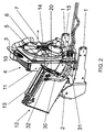
- FIG 2 shows the same arrangement in the cleaning position.
- the oil cooler 12 has been pivoted away from the radiator 3 over nearly a square angle about the hinge axis 20.
- the oil cooler 12 is no obstructed in its pivotal movement by the head portion 12. It is now possible to clean the oil cooler 12 on its exposed side by thoroughly blowing through it over its full surface.
- the flexible oil tubes 30 may accommodate the pivotal movement of the oil cooler 12 without any problem and without any substantial change of their position. If the oil cooler 12 is then pivoted back into its operational position according to Figure 1, it may be fixed in this position by means of a latch or catch or similar means not shown.
Landscapes
- Engineering & Computer Science (AREA)
- Chemical & Material Sciences (AREA)
- Combustion & Propulsion (AREA)
- Mechanical Engineering (AREA)
- General Engineering & Computer Science (AREA)
- Cooling, Air Intake And Gas Exhaust, And Fuel Tank Arrangements In Propulsion Units (AREA)
- Motor Or Generator Cooling System (AREA)
Abstract
Description
- The present invention relates to a motor vehicle having an oil cooler disposed in front of a radiator as seen in the direction of flow of the cooling medium therethrough, said radiator having an inflow and an outflow surface, two side surfaces as well as top and bottom surfaces.
- Oil coolers are used in conjunction with motor vehicles for cooling the motor oil and/or the transmission oil. With utility vehicles, and especially agricultural vehicles, they are also used to cool the operating fluid of lifting devices or other systems. In most cases, these oil coolers are disposed immediately in front of or behind the radiator and parallel thereto, depending on whether the cooling fan is disposed in front of or behind the radiator.
- To maintain the cooling efficiency of an oil cooler at an acceptable level, even in a contaminated environment, it has to be cleaned periodically. This is usually done by blowing air or a liquid through the oil cooler in a direction opposite to the direction of flow of the cooling medium during normal operation. For this purpose, the oil cooler has to be moved sufficiently far away from the radiator so that it is accessible from the rear side, especially when it is mounted in front of the radiator.
- In most cases it will be necessary to uninstall the oil-cooler, involving a substantial expense of time. From the STEYR-tractors of the series 91 it is known to pivot the oil cooler in its own plane parallel to the inflow surface about an axis extending along the direction of flow of the cooling medium. However, since the coolers are installed in a vehicle, this pivotal movement is possible only in a limited manner such that a portion of the surface to be cleaned always will remain inaccessible. The pivotal movement is not only limited by the wheels and the frame of the vehicle but also - in the case of an agricultural utility vehicle - also by the front lift device or by the ballast weights.
- It is therefore an object of the invention to propose an arrangement of the oil cooler which allows an unimpaired access to the complete surface to be cleaned with a minimum of time and constructional expenses.
- For this purpose and in accordance with the invention, the oil cooler is pivotably mounted by means of at least one hinge to one of the side surfaces of the radiator and is pivotable away therefrom. The oil cooler therefore may be pivoted to the side - similar to a door. Even if it is pivoted only about a square angle, it is fully accessible for cleaning purposes. No oil conducts have to be removed if these are at least partially constituted by flexible tubes. In view of the hinge movement, there is only a small change of the length of these flexible tubes, such that a short loop is sufficient to accommodate the movement.
- According to a further aspect of the present invention, the hinge axis of said at least one hinge is inclined at an angle relative to a vertical line. By inclining the hinge axis, the path of movement of the pivoting oil cooler may be modified such that no collision will occur with components which would hinder this movement in case a vertical hinge axis would be employed.
- According to a preferred embodiment of the invention, said angle is an acute angle directed relative to a vertical line in a combined forward and downward direction. On pivoting away, the oil cooler therefore initially follows a path directed upwardly such that it avoids obstacles in front of it. Such obstacles may be: frame portions, a bumper, parts of the front lift device, or ballast weights.
- A non-limiting embodiment of the present invention will now be described by way of example with reference to the accompanying drawings, in which:
- Figure 1 is a perspective view showing the subject of the present invention in a first position; and
- Figure 2 is a view similar to Figure 1 but showing the subject of the invention in a second position under a different angle of view.
-
- In Figure 1, the chassis or frame of a vehicle is only partly shown and indicated with
reference number 1. This may represent the vehicle chassis, a front axle support body, or the support of a lifting unit. In the last mentioned case, the frame itself is not shown. Thisframe 1 ends at its front end in ahead portion 2 which equally well may be a portion of the body of a vehicle, the bumper, or a support for the ballast weights. A radiator 8 or water cooler is fixedly mounted to thisframe 1. The radiator is a plane, flat box having an inflow surface 4 (hidden) and an outflow surface 5 (see figure 2) which is partly hidden by a radiator cowling. In the embodiment shown, the plane of the inflow andoutflow surfaces reference number 7. - Between its
inflow surface 4 andoutflow surface 5, theradiator 3 is surrounded by top and bottom surfaces and side surfaces, only onetop surface 10 and oneside surface 11 being visible. In front of theradiator 3, i.e. in upstream direction relative to the direction offlow 7, anoil cooler 12 is provided. The oil cooler is also a flat box extending mainly in a plane parallel to theinflow surface 4 of the radiator. Also only oneside surface 13 of the oil cooler may be seen in the drawings. In Figure 1, the oil cooler is disposed in the operational position. - The
side surface 13 of theoil cooler 12 and theside surface 11 of theradiator 3 are disposed in the same plane and are pivotally connected with one another by means of twohinges side surfaces angle 21 in a combined forward and downward direction. - The
oil cooler 12 is connected viaflexible oil tubes 30 andoil pipes 31 to the components to be cooled (engine, transmission and so on). Theflexible oil tubes 30 are provided between theoil pipes 31 guided along theradiator 3 andfittings 32 arranged on theoil cooler 12, respectively. - Figure 2 shows the same arrangement in the cleaning position. The
oil cooler 12 has been pivoted away from theradiator 3 over nearly a square angle about thehinge axis 20. As a result of the inclined installation of thehinge axis 20, theoil cooler 12 is no obstructed in its pivotal movement by thehead portion 12. It is now possible to clean theoil cooler 12 on its exposed side by thoroughly blowing through it over its full surface. Theflexible oil tubes 30 may accommodate the pivotal movement of theoil cooler 12 without any problem and without any substantial change of their position. If theoil cooler 12 is then pivoted back into its operational position according to Figure 1, it may be fixed in this position by means of a latch or catch or similar means not shown.
Claims (6)
- An oil cooler (12) for a motor vehicle which is disposed in front of a radiator (3) as seen in the direction of flow of a cooling medium, said radiator (3) having an inflow and an outflow surface (4, 5), two side surfaces (11), and a top and bottom surface (10, -), and
characterized in that said oil cooler (12) is pivotably mounted to one of the side surfaces (11) of the radiator (3) by means of at least one hinge (14, 15) and may be pivoted away from said radiator (3). - An oil cooler according to claim 1, characterized in that the hinge axis (20) of said at least one hinge (14, 15) is inclined relative to a vertical line by an angle (21).
- An oil cooler according to claim 2, characterized in that said angle (21) is an acute angle directed in a combined forward and downward direction relative to a vertical line.
- An oil cooler according to any of the preceding claims, characterized in that at least part of the oil conducts (30, 31) leading oil to and from the oil cooler (12) are flexible.
- A motor vehicle characterized in that it comprises an oil cooler (12) in accordance with any of the preceding claims.
- A motor vehicle according to claim 5, characterized in that a vehicle chassis part (2) is located in close proximity in front of said cooler (12) as seen in the flow direction of the cooling medium through the cooler (12) and comprises a top portion which extends above the bottom surface (-) of the cooler; said at least one hinge (14, 15) being arranged such that, upon pivoting the cooler (12) away from the radiator (3), part of the cooler (12) is lifted to procure unobstructed passage of at least part of the cooler (12) over and above said top portion of the vehicle chassis part (2).
Applications Claiming Priority (2)
| Application Number | Priority Date | Filing Date | Title |
|---|---|---|---|
| AT186999 | 1999-11-05 | ||
| AT186999 | 1999-11-05 |
Publications (3)
| Publication Number | Publication Date |
|---|---|
| EP1098073A2 true EP1098073A2 (en) | 2001-05-09 |
| EP1098073A3 EP1098073A3 (en) | 2003-03-19 |
| EP1098073B1 EP1098073B1 (en) | 2006-12-13 |
Family
ID=3522766
Family Applications (1)
| Application Number | Title | Priority Date | Filing Date |
|---|---|---|---|
| EP00203695A Expired - Lifetime EP1098073B1 (en) | 1999-11-05 | 2000-10-24 | Motor vehicle having an oil cooler |
Country Status (3)
| Country | Link |
|---|---|
| EP (1) | EP1098073B1 (en) |
| AT (1) | ATE348252T1 (en) |
| DE (1) | DE60032318T2 (en) |
Cited By (6)
| Publication number | Priority date | Publication date | Assignee | Title |
|---|---|---|---|---|
| EP1450019A1 (en) * | 2003-02-21 | 2004-08-25 | SAME DEUTZ-FAHR GROUP S.p.A. | Cooling system for a farm machine |
| GB2444505A (en) * | 2006-12-04 | 2008-06-11 | Cnh Uk Ltd | Heat exchanger mounting |
| EP2543775A4 (en) * | 2010-12-24 | 2013-11-13 | Komatsu Mfg Co Ltd | Construction vehicle |
| US8672071B2 (en) | 2011-09-21 | 2014-03-18 | Deere & Company | Fluid cooler arrangement for a cooling package in a work vehicle |
| US8960342B2 (en) | 2011-02-22 | 2015-02-24 | Deere & Company | Swing-out coolers and cooling fans |
| US9441892B2 (en) * | 2006-12-11 | 2016-09-13 | Deere & Company | Stacked heat exchanger system with swing-out heat exchangers |
Family Cites Families (5)
| Publication number | Priority date | Publication date | Assignee | Title |
|---|---|---|---|---|
| US3297080A (en) * | 1965-03-04 | 1967-01-10 | Int Harvester Co | Swing out oil cooler mounting |
| US3334704A (en) * | 1965-06-11 | 1967-08-08 | Int Harvester Co | Vehicle heat exchanger assembly |
| JPH0392525U (en) * | 1990-01-12 | 1991-09-20 | ||
| JPH1182023A (en) * | 1997-09-04 | 1999-03-26 | Hitachi Constr Mach Co Ltd | Construction machine |
| JP2001041043A (en) * | 1999-07-23 | 2001-02-13 | Shin Caterpillar Mitsubishi Ltd | Cleaning facilitating structure for cooler |
-
2000
- 2000-10-24 EP EP00203695A patent/EP1098073B1/en not_active Expired - Lifetime
- 2000-10-24 AT AT00203695T patent/ATE348252T1/en active
- 2000-10-24 DE DE60032318T patent/DE60032318T2/en not_active Expired - Lifetime
Non-Patent Citations (1)
| Title |
|---|
| None |
Cited By (8)
| Publication number | Priority date | Publication date | Assignee | Title |
|---|---|---|---|---|
| EP1450019A1 (en) * | 2003-02-21 | 2004-08-25 | SAME DEUTZ-FAHR GROUP S.p.A. | Cooling system for a farm machine |
| US7089994B2 (en) | 2003-02-21 | 2006-08-15 | Same Deutz-Fahr Group S.P.A. | Cooling system for a farm machine |
| GB2444505A (en) * | 2006-12-04 | 2008-06-11 | Cnh Uk Ltd | Heat exchanger mounting |
| US8096347B2 (en) | 2006-12-04 | 2012-01-17 | Cnh America Llc | Pivotable heat exchanger mounting |
| US9441892B2 (en) * | 2006-12-11 | 2016-09-13 | Deere & Company | Stacked heat exchanger system with swing-out heat exchangers |
| EP2543775A4 (en) * | 2010-12-24 | 2013-11-13 | Komatsu Mfg Co Ltd | Construction vehicle |
| US8960342B2 (en) | 2011-02-22 | 2015-02-24 | Deere & Company | Swing-out coolers and cooling fans |
| US8672071B2 (en) | 2011-09-21 | 2014-03-18 | Deere & Company | Fluid cooler arrangement for a cooling package in a work vehicle |
Also Published As
| Publication number | Publication date |
|---|---|
| EP1098073A3 (en) | 2003-03-19 |
| EP1098073B1 (en) | 2006-12-13 |
| ATE348252T1 (en) | 2007-01-15 |
| DE60032318D1 (en) | 2007-01-25 |
| DE60032318T2 (en) | 2007-03-29 |
Similar Documents
| Publication | Publication Date | Title |
|---|---|---|
| US6880656B2 (en) | Cooler arrangement for agricultural implements | |
| US6105660A (en) | Oil cooler movably supported on a vehicle and method for same | |
| US7255189B2 (en) | Radiator mounting system | |
| US8162087B2 (en) | Construction machine | |
| CA2787814C (en) | Radiator configuration | |
| US6435264B1 (en) | Cooling system for working vehicle | |
| CA1109456A (en) | Modular heat exchanger with pivotal cores | |
| EP1968813B1 (en) | Tractor cooling installation | |
| US20140056729A1 (en) | Radiator Configuration | |
| AU599873B2 (en) | Air cooling of radiator mounted in the rear of a powered implement | |
| US20110277961A1 (en) | Vehicle Cooling System | |
| CA1195361A (en) | Engine compartment enclosure | |
| EP1098073B1 (en) | Motor vehicle having an oil cooler | |
| JP2000212995A (en) | Oil cooler open and close mechanism for construction vehicle | |
| EP3022416B1 (en) | Fan shroud on an agricultural vehicle | |
| US9676271B1 (en) | Vehicle cooling arrangement | |
| US5881479A (en) | Apparatus for cooling a vehicle carrying a snowplow | |
| USRE30766E (en) | Modular heat exchanger with pivotal cores | |
| CA3011658C (en) | Dump truck | |
| WO2016012030A1 (en) | Cooling arrangement on an agricultural vehicle | |
| JP3735012B2 (en) | Construction machinery | |
| WO2019197790A1 (en) | Air inlet module in particular for a motor vehicle | |
| JPH024770B2 (en) | ||
| JP2026068266A (en) | Work vehicles | |
| JP2026068263A (en) | Work vehicles |
Legal Events
| Date | Code | Title | Description |
|---|---|---|---|
| PUAI | Public reference made under article 153(3) epc to a published international application that has entered the european phase |
Free format text: ORIGINAL CODE: 0009012 |
|
| AK | Designated contracting states |
Kind code of ref document: A2 Designated state(s): AT BE CH CY DE DK ES FI FR GB GR IE IT LI LU MC NL PT SE |
|
| AX | Request for extension of the european patent |
Free format text: AL;LT;LV;MK;RO;SI |
|
| RAP1 | Party data changed (applicant data changed or rights of an application transferred) |
Owner name: CNH OESTERREICH GMBH |
|
| PUAL | Search report despatched |
Free format text: ORIGINAL CODE: 0009013 |
|
| AK | Designated contracting states |
Kind code of ref document: A3 Designated state(s): AT BE CH CY DE DK ES FI FR GB GR IE IT LI LU MC NL PT SE |
|
| AX | Request for extension of the european patent |
Extension state: AL LT LV MK RO SI |
|
| 17P | Request for examination filed |
Effective date: 20030909 |
|
| AKX | Designation fees paid |
Designated state(s): AT BE CH CY DE DK ES FI FR GB GR IE IT LI LU MC NL PT SE |
|
| GRAP | Despatch of communication of intention to grant a patent |
Free format text: ORIGINAL CODE: EPIDOSNIGR1 |
|
| GRAS | Grant fee paid |
Free format text: ORIGINAL CODE: EPIDOSNIGR3 |
|
| GRAA | (expected) grant |
Free format text: ORIGINAL CODE: 0009210 |
|
| AK | Designated contracting states |
Kind code of ref document: B1 Designated state(s): AT BE CH CY DE DK ES FI FR GB GR IE IT LI LU MC NL PT SE |
|
| PG25 | Lapsed in a contracting state [announced via postgrant information from national office to epo] |
Ref country code: BE Free format text: LAPSE BECAUSE OF FAILURE TO SUBMIT A TRANSLATION OF THE DESCRIPTION OR TO PAY THE FEE WITHIN THE PRESCRIBED TIME-LIMIT Effective date: 20061213 Ref country code: FI Free format text: LAPSE BECAUSE OF FAILURE TO SUBMIT A TRANSLATION OF THE DESCRIPTION OR TO PAY THE FEE WITHIN THE PRESCRIBED TIME-LIMIT Effective date: 20061213 Ref country code: CH Free format text: LAPSE BECAUSE OF FAILURE TO SUBMIT A TRANSLATION OF THE DESCRIPTION OR TO PAY THE FEE WITHIN THE PRESCRIBED TIME-LIMIT Effective date: 20061213 Ref country code: DK Free format text: LAPSE BECAUSE OF FAILURE TO SUBMIT A TRANSLATION OF THE DESCRIPTION OR TO PAY THE FEE WITHIN THE PRESCRIBED TIME-LIMIT Effective date: 20061213 Ref country code: NL Free format text: LAPSE BECAUSE OF FAILURE TO SUBMIT A TRANSLATION OF THE DESCRIPTION OR TO PAY THE FEE WITHIN THE PRESCRIBED TIME-LIMIT Effective date: 20061213 Ref country code: LI Free format text: LAPSE BECAUSE OF FAILURE TO SUBMIT A TRANSLATION OF THE DESCRIPTION OR TO PAY THE FEE WITHIN THE PRESCRIBED TIME-LIMIT Effective date: 20061213 |
|
| REG | Reference to a national code |
Ref country code: GB Ref legal event code: FG4D |
|
| REG | Reference to a national code |
Ref country code: CH Ref legal event code: EP |
|
| REG | Reference to a national code |
Ref country code: IE Ref legal event code: FG4D |
|
| REF | Corresponds to: |
Ref document number: 60032318 Country of ref document: DE Date of ref document: 20070125 Kind code of ref document: P |
|
| PG25 | Lapsed in a contracting state [announced via postgrant information from national office to epo] |
Ref country code: SE Free format text: LAPSE BECAUSE OF FAILURE TO SUBMIT A TRANSLATION OF THE DESCRIPTION OR TO PAY THE FEE WITHIN THE PRESCRIBED TIME-LIMIT Effective date: 20070313 |
|
| PG25 | Lapsed in a contracting state [announced via postgrant information from national office to epo] |
Ref country code: ES Free format text: LAPSE BECAUSE OF FAILURE TO SUBMIT A TRANSLATION OF THE DESCRIPTION OR TO PAY THE FEE WITHIN THE PRESCRIBED TIME-LIMIT Effective date: 20070324 |
|
| PG25 | Lapsed in a contracting state [announced via postgrant information from national office to epo] |
Ref country code: PT Free format text: LAPSE BECAUSE OF FAILURE TO SUBMIT A TRANSLATION OF THE DESCRIPTION OR TO PAY THE FEE WITHIN THE PRESCRIBED TIME-LIMIT Effective date: 20070514 |
|
| ET | Fr: translation filed | ||
| NLV1 | Nl: lapsed or annulled due to failure to fulfill the requirements of art. 29p and 29m of the patents act | ||
| REG | Reference to a national code |
Ref country code: CH Ref legal event code: PL |
|
| PLBE | No opposition filed within time limit |
Free format text: ORIGINAL CODE: 0009261 |
|
| STAA | Information on the status of an ep patent application or granted ep patent |
Free format text: STATUS: NO OPPOSITION FILED WITHIN TIME LIMIT |
|
| 26N | No opposition filed |
Effective date: 20070914 |
|
| PG25 | Lapsed in a contracting state [announced via postgrant information from national office to epo] |
Ref country code: GR Free format text: LAPSE BECAUSE OF FAILURE TO SUBMIT A TRANSLATION OF THE DESCRIPTION OR TO PAY THE FEE WITHIN THE PRESCRIBED TIME-LIMIT Effective date: 20070314 |
|
| PG25 | Lapsed in a contracting state [announced via postgrant information from national office to epo] |
Ref country code: MC Free format text: LAPSE BECAUSE OF NON-PAYMENT OF DUE FEES Effective date: 20071031 |
|
| PG25 | Lapsed in a contracting state [announced via postgrant information from national office to epo] |
Ref country code: IE Free format text: LAPSE BECAUSE OF NON-PAYMENT OF DUE FEES Effective date: 20071024 |
|
| PG25 | Lapsed in a contracting state [announced via postgrant information from national office to epo] |
Ref country code: LU Free format text: LAPSE BECAUSE OF NON-PAYMENT OF DUE FEES Effective date: 20071024 Ref country code: CY Free format text: LAPSE BECAUSE OF FAILURE TO SUBMIT A TRANSLATION OF THE DESCRIPTION OR TO PAY THE FEE WITHIN THE PRESCRIBED TIME-LIMIT Effective date: 20061213 |
|
| PGFP | Annual fee paid to national office [announced via postgrant information from national office to epo] |
Ref country code: AT Payment date: 20131021 Year of fee payment: 14 |
|
| REG | Reference to a national code |
Ref country code: DE Ref legal event code: R082 Ref document number: 60032318 Country of ref document: DE Representative=s name: PATENTANWAELTE WALLACH, KOCH & PARTNER, DE |
|
| REG | Reference to a national code |
Ref country code: DE Ref legal event code: R081 Ref document number: 60032318 Country of ref document: DE Owner name: CNH INDUSTRIAL OESTERREICH GMBH, AT Free format text: FORMER OWNER: CNH OESTERREICH GMBH, SANKT VALENTIN, AT Effective date: 20140422 Ref country code: DE Ref legal event code: R082 Ref document number: 60032318 Country of ref document: DE Representative=s name: PATENTANWAELTE WALLACH, KOCH, DR. HAIBACH, FEL, DE Effective date: 20140422 Ref country code: DE Ref legal event code: R082 Ref document number: 60032318 Country of ref document: DE Representative=s name: PATENTANWAELTE WALLACH, KOCH & PARTNER, DE Effective date: 20140422 |
|
| REG | Reference to a national code |
Ref country code: AT Ref legal event code: MM01 Ref document number: 348252 Country of ref document: AT Kind code of ref document: T Effective date: 20141024 |
|
| PG25 | Lapsed in a contracting state [announced via postgrant information from national office to epo] |
Ref country code: AT Free format text: LAPSE BECAUSE OF NON-PAYMENT OF DUE FEES Effective date: 20141024 |
|
| REG | Reference to a national code |
Ref country code: FR Ref legal event code: PLFP Year of fee payment: 16 |
|
| PGFP | Annual fee paid to national office [announced via postgrant information from national office to epo] |
Ref country code: DE Payment date: 20151009 Year of fee payment: 16 Ref country code: IT Payment date: 20151005 Year of fee payment: 16 Ref country code: GB Payment date: 20151008 Year of fee payment: 16 |
|
| PGFP | Annual fee paid to national office [announced via postgrant information from national office to epo] |
Ref country code: FR Payment date: 20151006 Year of fee payment: 16 |
|
| REG | Reference to a national code |
Ref country code: DE Ref legal event code: R119 Ref document number: 60032318 Country of ref document: DE |
|
| GBPC | Gb: european patent ceased through non-payment of renewal fee |
Effective date: 20161024 |
|
| REG | Reference to a national code |
Ref country code: FR Ref legal event code: ST Effective date: 20170630 |
|
| PG25 | Lapsed in a contracting state [announced via postgrant information from national office to epo] |
Ref country code: FR Free format text: LAPSE BECAUSE OF NON-PAYMENT OF DUE FEES Effective date: 20161102 Ref country code: GB Free format text: LAPSE BECAUSE OF NON-PAYMENT OF DUE FEES Effective date: 20161024 Ref country code: DE Free format text: LAPSE BECAUSE OF NON-PAYMENT OF DUE FEES Effective date: 20170503 |
|
| PG25 | Lapsed in a contracting state [announced via postgrant information from national office to epo] |
Ref country code: IT Free format text: LAPSE BECAUSE OF NON-PAYMENT OF DUE FEES Effective date: 20161024 |