EP1098045A1 - A curtain wall with panels suspended at points - Google Patents
A curtain wall with panels suspended at points Download PDFInfo
- Publication number
- EP1098045A1 EP1098045A1 EP99830694A EP99830694A EP1098045A1 EP 1098045 A1 EP1098045 A1 EP 1098045A1 EP 99830694 A EP99830694 A EP 99830694A EP 99830694 A EP99830694 A EP 99830694A EP 1098045 A1 EP1098045 A1 EP 1098045A1
- Authority
- EP
- European Patent Office
- Prior art keywords
- panels
- wall according
- support elements
- panel
- wall
- Prior art date
- Legal status (The legal status is an assumption and is not a legal conclusion. Google has not performed a legal analysis and makes no representation as to the accuracy of the status listed.)
- Withdrawn
Links
Images


Classifications
-
- E—FIXED CONSTRUCTIONS
- E06—DOORS, WINDOWS, SHUTTERS, OR ROLLER BLINDS IN GENERAL; LADDERS
- E06B—FIXED OR MOVABLE CLOSURES FOR OPENINGS IN BUILDINGS, VEHICLES, FENCES OR LIKE ENCLOSURES IN GENERAL, e.g. DOORS, WINDOWS, BLINDS, GATES
- E06B3/00—Window sashes, door leaves, or like elements for closing wall or like openings; Layout of fixed or moving closures, e.g. windows in wall or like openings; Features of rigidly-mounted outer frames relating to the mounting of wing frames
- E06B3/54—Fixing of glass panes or like plates
- E06B3/5436—Fixing of glass panes or like plates involving holes or indentations in the pane
- E06B3/5445—Support arms engaging the holes or indentations
-
- E—FIXED CONSTRUCTIONS
- E04—BUILDING
- E04B—GENERAL BUILDING CONSTRUCTIONS; WALLS, e.g. PARTITIONS; ROOFS; FLOORS; CEILINGS; INSULATION OR OTHER PROTECTION OF BUILDINGS
- E04B2/00—Walls, e.g. partitions, for buildings; Wall construction with regard to insulation; Connections specially adapted to walls
- E04B2/88—Curtain walls
- E04B2/885—Curtain walls comprising a supporting structure for flush mounted glazing panels
-
- E—FIXED CONSTRUCTIONS
- E06—DOORS, WINDOWS, SHUTTERS, OR ROLLER BLINDS IN GENERAL; LADDERS
- E06B—FIXED OR MOVABLE CLOSURES FOR OPENINGS IN BUILDINGS, VEHICLES, FENCES OR LIKE ENCLOSURES IN GENERAL, e.g. DOORS, WINDOWS, BLINDS, GATES
- E06B3/00—Window sashes, door leaves, or like elements for closing wall or like openings; Layout of fixed or moving closures, e.g. windows in wall or like openings; Features of rigidly-mounted outer frames relating to the mounting of wing frames
- E06B3/54—Fixing of glass panes or like plates
- E06B3/5436—Fixing of glass panes or like plates involving holes or indentations in the pane
Definitions
- the present invention relates to curtain walls with panels suspended at points, according to the preamble to Claim 1.
- Walls of this type which are known, for example, from EP-A-0 201 212, are used to produce facades of particularly light structure, constituted wholly or partly by glazed elements, and also characterized by particular transparency and brightness.
- a disadvantage which may be encountered in these structures is due to an absence of ventilation openings in the wall formed by the panels. This is a considerable disadvantage in countries in which the health and hygiene standards in force deem ventilation of areas exclusively by means other than an ability to open the walls defining the areas to be unsatisfactory except in certain conditions.
- the object of the present invention is therefore to provide curtain walls with suspended panels by means of which it is possible to ventilate the rooms selectively.
- a wall constituted by panels suspended at points is generally indicated 1.
- the wall in question is a facade delimiting a portion of a building E shown in the drawings as comprising a plurality of slabs S supported by one or more columns P. It is, however, quite clear that the characteristics of the building per se do not influence the characteristics of the wall according to the invention.
- the wall 1 comprises a load-bearing structure 2 configured as a structure of the type currently known (perhaps not entirely correctly) as a "tension structure".
- this is a structure constituted by a plurality of generally arcuate tubular ribs 3 extending between respective anchoring structures 31 and 32 situated at the bottom and at the top of the wall, respectively, for connection to the slabs S and/or to the columns P.
- the ribs in question have respective associated ties 4 and 5 extending between respective anchorage regions 41, 42 and 51, 52, on the outer and inner surfaces of the wall 1, respectively.
- outer and inner refer to the location of the wall relative to the building E.
- the ties 4 and 5 cooperate with the ribs 3 by means of respective struts 43 (outer tie 4) and 53 (inner tie 5).
- Inner struts 53 are also visible in Figure 2 in which their head portions 53a, which are split so that the tie 5 (not shown in Figure 2) can extend through them, are clearly visible.
- the fork-like elements 6 are intended to support a set of panels 7 which are suspended at points on the structure 2 (in accordance with the criteria described further below) and constitute the actual curtain of the wall 1.
- the panels 7 are made of transparent material, preferably of the type currently known as double glazing.
- this solution is not essential; it is in fact possible, for example, to provide for the opening movement to take place outwardly and/or as a result of a pivoting movement about an axis located at the upper edge or in the centre of the panel and/or as a result of an orientation movement about an axis which, instead of being horizontal as in the embodiment illustrated, is oriented vertically (thus being located adjacent one of the vertical sides of the panel 7) and/or is inclined.
- the orientation movement takes place about horizontal axes X7 located at the lower edges of the panels 7, the axes X7 in fact being identified by two "fixed" support elements 8 carried by respective limbs of the support forks 6.
- the forks 6 extend from the respective ribs 3 towards the panels 7 with two diverging limbs extending on either side of the strut 53 located in the same position. Since the ribs 6 extend practically on the boundary between two adjacent columns of panels 7 disposed one above another, the limbs extend towards one and towards the other of the two adjacent columns of panels 7, respectively.
- the embodiment illustrated herein - which is described by way of example - relates to a solution in which the opening movement affects alternate columns of panels 7 disposed one above another.
- the swivels 8 carried by the fork-like structure 81 are intended to support panels 7 which are not involved in the opening movement.
- each swivel 8 is constituted basically by a stem 10 which carries at one end an orientable head 11 connected to the stem 10 by means of a ball and socket joint (hence the name "swivel") which can be oriented so as to permit the desired opening movement of the panels 7.
- the stem 10 is configured substantially in the form of a threaded pin which extends through an eye 821 provided at the distal end of each arm of the fork 81, or of each arm 82, so that it can be locked in the desired position by means of two nuts 822, preferably with the interposition of rings of vibration-damping material.
- the orientable head 11 is usually in the form of a cylindrical body which can extend through a bore 12 provided in the body of the panel 7 so as to define a corresponding suspension point.
- the bore 12 can house a locking element 13 substantially comparable to a screw with a conical and milled head which restrains the panel 7 relative to the head 11.
- the structure of the swivels 8 may be considered known per se and hence does not require a detailed description herein.
- the solution described herein is given purely by way of example since the function described may be performed with the use of functionally equivalent solutions.
- the heads 11 could be connected to the panels 7 without the panels 7 being drilled and the heads 11 consequently extending through the bores 12, for example, by gluing the panels 7 to the articulated head portions of the swivels 8, or by means of functionally equivalent solutions.
- the embodiment described provides for the entire set of parts of the wall 1 which are intended to provide for the support of the panels 7 (and hence also for the relative movement, in the terms explained further below) to be located on the outer side of the wall 1.
- This solution has been found advantageous since it leaves the inner side of the wall 1, which is in fact defined by the curtain of panels 7, completely clear, and/or since it allows, for example, sun-screens such as the fins indicated 30 solely in Figure 1, to be mounted on the outside of the wall. Again, however, this is not an essential solution since a precisely complementary solution could be considered.
- swivels 8' generally similar to the swivels 8 described above.
- the main difference between the swivels 8 and the swivels 8' is that the swivels 8 are mounted in fixed positions relative to the forks 6 (and hence to the rest of the structure 2), whereas the swivels 8' can move relative to this portion of the structure.
- the limbs 6 which carry the upwardly extending arms 82 are arranged also to carry, extending downwardly and preferably away from the panels 7 (for obvious reasons of space), further arms 14 the distal ends of which support, preferably by means of an articulated joint 15 (for reasons which will become clearer from the following), a linear actuator 16 constituted, for example, by an electromagnetic actuator the cylinder 17 of which is articulated to the arm 14, for example by means of a bracket 18, and the rod 19 of which cooperates, for example, with the stem 10 of a respective swivel 8' by means of an adjustment sleeve 20.
- the reference L indicates the supply line for the driving means (electricity, but it could be air or pressurized fluid for fluid actuators 16) coming from a drive source, not shown, which enables the fluid for actuating the actuator 16 to be supplied and withdrawn.
- the two actuators 16 acting on the swivels 8' associated with the same panel are kinematically coupled to one another so as to move precisely in synchronism, preventing the application of undesired torsion/bending stresses to the panel 7 controlled thereby.
- connection is achieved (see Figure 2 in particular) by arranging for the two actuators 16 in question to be coupled to one another by means of a shaft 21 extending parallel to the lower edge of the respective panel.
- the solution according to the invention is characterized in that the support elements cooperating with at least one of the panels comprise a first set of support elements (the swivels 8) defining an orientation axis for the respective panel and a second set of support elements (the swivels 8') which are associated with the load-bearing structure with a capability for selective movement relative to the load-bearing structure.
- a first set of support elements the swivels 8
- the swivels 8' which are associated with the load-bearing structure with a capability for selective movement relative to the load-bearing structure.
- adjustment sleeves 20 enables the set of elements described to be adjusted precisely by ensuring that an identical positioning of the actuators 16 corresponds to an absence of stresses applied to the panels 7 by means of the swivels 8 carried thereby.
- Figure 3 relates to the closure condition in which the swivel 8' shown in the lower position in fact behaves (except for the different connection of the fork 6) in the same manner as the swivel 8 shown in the upper position.
- Figure 4 shows that, if the actuator 16 is activated by means of the line L, the rod 19 can be extracted from the body 17 causing the swivel 8' carried by the rod 19 to move the upper edge of the respective panel 7 (inwardly relative to the wall 1 in the embodiment shown), away from the lower edge of the panel 7 disposed in a position above it.
- FIG. 3 and 4 show how, in a preferred embodiment of the invention, the fact that the panels 7 are in the form of double-glazing panels enables an effective seal to be achieved when the panels 7 are in the closure position.
- each panel in question in the form of so-called double-glazing panels means that each panel is in fact constituted by two sheets of glass 70, 71.
- Sealing elements 32, 33 are interposed in the peripheral regions (and around the edges of the bores 12 if they are present) for ensuring that the internal cavities of the panels 7 are sealed against penetration of moisture, etc.
- the sheets 70, 71 are preferably connected to one another so as to be offset at least at the sides which are to cooperate with the sides of adjacent panels during the opening and closure movement, so as to permit coupling between the juxtaposed sides of adjacent panels 7 in an overlapping configuration, that is, in an at least partially superimposed arrangement.
- Sealing elements such as tubular weatherstrips 34 are usually interposed between the cooperating edges of adjacent panels (both vertically and horizontally), and are usually fixed by snap-coupling with the sealing elements 33 of the panels.
- At least one further lipped sealing element 35 may advantageously be provided along one or more of the sides of the panels 7.
- This element is formed, for example, so as to be generally Y-shaped and hence with two top portions which are intended to extend around one of the sheets (such as the sheet 71) and a projecting leg for cooperating with an adjacent panel 7 (see Figure 3).
Abstract
The wall (1) comprises a plurality of panels (7) each having
respective suspension points, as well as a load-bearing
structure (2), usually constituted by a tension structure,
with a plurality of support elements (8, 8') which cooperate
with the panels (7) at the suspension points. At least some
of the panels (7), which are preferably constituted by
glazed panels, have associated support elements (8') which
are mounted on the load-bearing structure with a capability
for movement so as to enable the respective panel (7) to be
oriented between a closure position in which the panel is
flush with the adjacent panels and at least one open
position in which the respective panel is displaced relative
to the adjacent panels, thus defining an opening in the wall
(1).
Description
- The present invention relates to curtain walls with panels suspended at points, according to the preamble to Claim 1.
- Walls of this type, which are known, for example, from EP-A-0 201 212, are used to produce facades of particularly light structure, constituted wholly or partly by glazed elements, and also characterized by particular transparency and brightness.
- A disadvantage which may be encountered in these structures is due to an absence of ventilation openings in the wall formed by the panels. This is a considerable disadvantage in countries in which the health and hygiene standards in force deem ventilation of areas exclusively by means other than an ability to open the walls defining the areas to be unsatisfactory except in certain conditions.
- The object of the present invention is therefore to provide curtain walls with suspended panels by means of which it is possible to ventilate the rooms selectively.
- According to the present invention, this object is achieved by a curtain wall with suspended panels having the specific characteristics recited in the appended claims.
- The invention will now be described, purely by way of nonlimiting example, with reference to the appended drawings, in which:
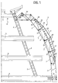
- Figure 1 is a general view showing a wall formed in accordance with the invention, in vertical section,
- Figure 2 is a perspective view, reproduced on an enlarged scale in comparison with Figure 1, showing in greater detail the criteria used to achieve the orientation of the panels in the wall of Figure 1, and
- Figures 3 and 4 show, on a further enlarged scale and from a viewpoint approximately corresponding to that identified by the arrow III of Figure 2, a first relative position and a second relative position, respectively, which can be reached by two panels included in the wall shown in Figures 1 and 2.
-
- In the appended drawings, a wall constituted by panels suspended at points is generally indicated 1.
- Specifically, the wall in question is a facade delimiting a portion of a building E shown in the drawings as comprising a plurality of slabs S supported by one or more columns P. It is, however, quite clear that the characteristics of the building per se do not influence the characteristics of the wall according to the invention.
- In the embodiment shown - which is illustrated by way of example - the wall 1 comprises a load-bearing structure 2 configured as a structure of the type currently known (perhaps not entirely correctly) as a "tension structure". In particular, in the embodiment shown, this is a structure constituted by a plurality of generally arcuate
tubular ribs 3 extending betweenrespective anchoring structures - The ribs in question have respective associated
ties respective anchorage regions - According to a known solution, the
ties ribs 3 by means of respective struts 43 (outer tie 4) and 53 (inner tie 5). - Some of the
inner struts 53 are also visible in Figure 2 in which theirhead portions 53a, which are split so that the tie 5 (not shown in Figure 2) can extend through them, are clearly visible. - Fork-like elements 6, projecting inwardly relative to the wall 1 from the
ribs 3 are also clearly visible in Figure 2. - The fork-like elements 6 are intended to support a set of
panels 7 which are suspended at points on the structure 2 (in accordance with the criteria described further below) and constitute the actual curtain of the wall 1. In the preferred embodiment of the invention, thepanels 7 are made of transparent material, preferably of the type currently known as double glazing. - Before describing the methods adopted for the connection of the
panels 7 to the structure 3 (with the further capability for at least some of the panels to be oriented towards an open position), it should be pointed out once more that the embodiment illustrated is only one possible example. - In particular, although the following list is not intended in any way to be exhaustive, experts in the art will easily appreciate that the solution according to the invention may be subjected to many possible variations with regard to various aspects such as:
- the external nature of the wall 1: it can readily be seen that, although the wall 1 is illustrated herein as an external wall of the building E, the same solution could be used in an internal wall, for example, a wall which is intended to face into a multi-storey hall;
- the general arrangement and shape of the wall: in the embodiment illustrated, the wall 1 is generally curved and inclined so that the respective outer and inner surfaces have the character of external and internal curved surfaces of an arcuate wall; clearly, the wall could be flat and/or curved differently and/or could have a horizontal or inclined orientation instead of being vertical or substantially vertical;
- the nature of the structure used for the point support of the panels 7: as already stated, the example given herein of a so-called tension structure is in no way limiting of the scope of the invention since the structure could have quite different characteristics, for example, it could be configured as a lattice structure;
- the nature of the panels 7: although the preferred field of application of the invention is for glazed walls, this is clearly not an essential requirement; the solution according to the invention may in fact be used in conjunction with panels of any type, and hence also with non-transparent panels and/or, in particular, to form walls comprising both transparent panels and non-transparent panels;
- the technology for the production of the panels: the following description refers, as the currently-preferred solution, (for reasons which will become clearer from the following), to the production of glazed panels of the type currently known as double-glazing panels; however, the technology for the production of the panels may clearly be of a different type, for example, providing for the use of moulded (transparent or non-transparent) panels;
- the fitting of the orientation mechanism: the embodiment
described further below relates to a solution in which the
wall 1 comprises a matrix-like array of
panels 7 in which thepanels 7 are divided theoretically into adjacent columns of panels disposed one above another, in which the opening mechanism is fitted alternately on the panels of one in every two columns; however, the solution according to the invention may clearly be implemented extremely freely with any combination of panels between the two extremes represented by an embodiment in which only one panel is orientable whilst all of the other panels are fixed, and an embodiment of a wall in which all of the panels are orientable, - the shape of the panels: the embodiment described herein
relates to substantially square or
rectangular panels 7; the solution according to the invention may, however, also be implemented in conjunction withpanels 7 of different shapes, such as, for example, parallelogram-shaped or rhombus-shaped panels or panels with mixtilinear outlines, particularly when the opening movement is provided for in only some panels of the wall; - the type of orientation movement, which is represented herein as a pivoting movement about a horizontal axis situated in the lower portion of the respective panel; clearly quite different selections, such as orientation about a vertical axis and/or about a side, upper or central region of the panel, are possible, and
- the use, for the point support of the panels, of support elements cooperating with the panels in an articulated (swivel) arrangement; the orientation of the panels brought about by the opening movement may in fact be allowed for differently, for example, by the provision of play between the panel or panels subject to the opening movement and the respective point support elements and/or by arranging for the latter to be orientable relative to the load-bearing structure 2 which supports them.
- It is also clear that the various alternatives given by way of example above may be combined with one another with the greatest freedom.
- With reference to Figures 2 to 4, it will be seen in the first place that, in the embodiment illustrated, the above-mentioned orientation (opening) movement of the
panels 7 takes place from a closure position (shown in Figure 3 and schematically by broken lines in Figure 2) towards an open position (shown by continuous lines in Figure 4 and in Figure 2), as a result of a movement of thepanels 7 inwardly relative to the wall 1. This orientation movement also takes place as a result of a pivoting of thepanel 7 involved about a horizontal axis located in the region of the lower edge of thepanel 7. This solution is currently preferred since, amongst other things, it means that the upper edge of eachpanel 7 is in fact protected against possible rain penetration in the open position by the lower side of the panel disposed above it. However, this solution is not essential; it is in fact possible, for example, to provide for the opening movement to take place outwardly and/or as a result of a pivoting movement about an axis located at the upper edge or in the centre of the panel and/or as a result of an orientation movement about an axis which, instead of being horizontal as in the embodiment illustrated, is oriented vertically (thus being located adjacent one of the vertical sides of the panel 7) and/or is inclined. - In the embodiment shown, the orientation movement takes place about horizontal axes X7 located at the lower edges of the
panels 7, the axes X7 in fact being identified by two "fixed"support elements 8 carried by respective limbs of the support forks 6. - The structure of these support elements (usually known as "swivels" in current terminology for panels with point suspension) is shown in greater detail in Figures 3 and 4.
- With reference to the perspective view of Figure 2, it will be appreciated that the forks 6 extend from the
respective ribs 3 towards thepanels 7 with two diverging limbs extending on either side of thestrut 53 located in the same position. Since the ribs 6 extend practically on the boundary between two adjacent columns ofpanels 7 disposed one above another, the limbs extend towards one and towards the other of the two adjacent columns ofpanels 7, respectively. - As already stated in the introductory portion of the present description, the embodiment illustrated herein - which is described by way of example - relates to a solution in which the opening movement affects alternate columns of
panels 7 disposed one above another. - This explains why, in the perspective view of Figure 2, two pairs of
swivels 8 are visible in an outer position relative to the column ofpanels 7 shown, with each pair of vertically alignedswivels 8 carried by a respective associated vertical fork-shaped structure 81 which in turn is associated with the distal end (supported by a wind-bracing tie 9 connected to the respective rib 3) of one of the limbs of the fork 6. - The
swivels 8 carried by the fork-like structure 81 are intended to supportpanels 7 which are not involved in the opening movement. - With regard to the
panels 7 which are involved in the opening movement, their lower ends are intended to be supported by swivels 8 (those which are visible in Figures 3 and 4 and are located in inner positions relative to the perspective view of Figure 2) carried byrespective arms 82 fixed to the distal ends (each supported by a respective tie 9) of the other limbs of the forks 6 already referred to above. Thearms 82 may be regarded to a certain extent simply as being equivalent to the above-describedforks 81, without the lower arms. - Without wishing to enter into a detailed description of a known structure (see for example EP-A-0 201 212), each
swivel 8 is constituted basically by astem 10 which carries at one end anorientable head 11 connected to thestem 10 by means of a ball and socket joint (hence the name "swivel") which can be oriented so as to permit the desired opening movement of thepanels 7. - In the embodiment shown, the
stem 10 is configured substantially in the form of a threaded pin which extends through aneye 821 provided at the distal end of each arm of thefork 81, or of eacharm 82, so that it can be locked in the desired position by means of twonuts 822, preferably with the interposition of rings of vibration-damping material. - Similarly, the
orientable head 11 is usually in the form of a cylindrical body which can extend through abore 12 provided in the body of thepanel 7 so as to define a corresponding suspension point. Thebore 12 can house alocking element 13 substantially comparable to a screw with a conical and milled head which restrains thepanel 7 relative to thehead 11. - As already stated, the structure of the
swivels 8 may be considered known per se and hence does not require a detailed description herein. In any case, the solution described herein is given purely by way of example since the function described may be performed with the use of functionally equivalent solutions. To give an example, theheads 11 could be connected to thepanels 7 without thepanels 7 being drilled and theheads 11 consequently extending through thebores 12, for example, by gluing thepanels 7 to the articulated head portions of theswivels 8, or by means of functionally equivalent solutions. - It should also be noted that the embodiment described provides for the entire set of parts of the wall 1 which are intended to provide for the support of the panels 7 (and hence also for the relative movement, in the terms explained further below) to be located on the outer side of the wall 1. This solution has been found advantageous since it leaves the inner side of the wall 1, which is in fact defined by the curtain of
panels 7, completely clear, and/or since it allows, for example, sun-screens such as the fins indicated 30 solely in Figure 1, to be mounted on the outside of the wall. Again, however, this is not an essential solution since a precisely complementary solution could be considered. - The upper sides of the
panels 7 involved in the opening movement are supported by thestructure 3 by means of swivels 8' generally similar to theswivels 8 described above. - This applies in particular with regard to the structure of the
orientable heads 11 which are connected to theglazed panels 7 by being inserted throughbores 12, thepanels 7 then being locked by means of thescrews 13. - Naturally, this also applies with regard to the possible variants mentioned above (the possible fixing of the
heads 11 to thepanels 7 by gluing, etc.) but does not mean that the swivels 8' necessarily have to be identical to theswivels 8 with regard to the parts indicated by the same reference numerals. - The main difference between the
swivels 8 and the swivels 8' is that theswivels 8 are mounted in fixed positions relative to the forks 6 (and hence to the rest of the structure 2), whereas the swivels 8' can move relative to this portion of the structure. - In particular, in the embodiment shown, the limbs 6 which carry the upwardly extending
arms 82 are arranged also to carry, extending downwardly and preferably away from the panels 7 (for obvious reasons of space),further arms 14 the distal ends of which support, preferably by means of an articulated joint 15 (for reasons which will become clearer from the following), alinear actuator 16 constituted, for example, by an electromagnetic actuator thecylinder 17 of which is articulated to thearm 14, for example by means of abracket 18, and therod 19 of which cooperates, for example, with thestem 10 of a respective swivel 8' by means of anadjustment sleeve 20. - The reference L indicates the supply line for the driving means (electricity, but it could be air or pressurized fluid for fluid actuators 16) coming from a drive source, not shown, which enables the fluid for actuating the
actuator 16 to be supplied and withdrawn. - It will be appreciated, however, that the arrangement of the
actuators 16 could be reversed, that is, with therod 19 connected to thearm 14 and the cylinder ofbody 17 connected to thepin 10. - It is also clear that the reference to an electromagnetic actuator (which is currently considered the preferable selection for reasons of reliability and precision of movement) is not essential since the function required, that is, that of selectively varying the distance between the arms 14 (and the
structure 3 in general) and theheads 11 of the swivels 8' connected to the upper ends of thepanels 7 which are subjected to the opening movement could be achieved by actuators of another type such as, for example, fluid jacks or motors. - Whatever solution is adopted, the two
actuators 16 acting on the swivels 8' associated with the same panel are kinematically coupled to one another so as to move precisely in synchronism, preventing the application of undesired torsion/bending stresses to thepanel 7 controlled thereby. - In the embodiment illustrated, the above-mentioned connection is achieved (see Figure 2 in particular) by arranging for the two
actuators 16 in question to be coupled to one another by means of ashaft 21 extending parallel to the lower edge of the respective panel. - It can thus be understood that, although the embodiment described herein refers to the upper edge of the
panel 7 being supported by means of two swivels 8' with respective associatedactuators 16, the same result could also be achieved with the use of only oneactuator 16 acting on a pair of swivels 8' by means of a transmission mechanism (such as theshaft 21 shown in Figure 2), or simply by supporting eachpanel 7 at its upper edge by means of a single swivel 8', for example, located in a central position, with a respective associated actuator; any necessary structural adaptations are within the capabilities of an expert in the art and do not need to be described herein. - Basically, the solution according to the invention is characterized in that the support elements cooperating with at least one of the panels comprise a first set of support elements (the swivels 8) defining an orientation axis for the respective panel and a second set of support elements (the swivels 8') which are associated with the load-bearing structure with a capability for selective movement relative to the load-bearing structure. This brings about the movement of the respective panel between:
- a closure position (shown in Figure 3) in which the respective panel is flush with the adjacent panels, and
- at least one second position (shown in Figure 4) in which, as a result of pivoting about the orientation axis, the respective panel is displaced relative to the adjacent panels, thus defining an opening in the wall.
- The presence of the
adjustment sleeves 20 enables the set of elements described to be adjusted precisely by ensuring that an identical positioning of theactuators 16 corresponds to an absence of stresses applied to thepanels 7 by means of theswivels 8 carried thereby. - The mechanism for opening the
panels 7 can be understood easily from a comparison of Figures 3 and 4. - Figure 3 relates to the closure condition in which the swivel 8' shown in the lower position in fact behaves (except for the different connection of the fork 6) in the same manner as the
swivel 8 shown in the upper position. - Figure 4, on the other hand, shows that, if the
actuator 16 is activated by means of the line L, therod 19 can be extracted from thebody 17 causing the swivel 8' carried by therod 19 to move the upper edge of the respective panel 7 (inwardly relative to the wall 1 in the embodiment shown), away from the lower edge of thepanel 7 disposed in a position above it. - It will also be appreciated from a comparison of Figures 3 and 4 that the lower edge has also undergone a slight angular movement (anticlockwise with reference to the viewpoint of the drawings) resulting from the opening movement which is assumed here to have been imparted simultaneously to the upper edge (not shown) of the
same panel 7. As already stated - the opening movement may, however, also involve only onepanel 7. - The detail views of Figures 3 and 4 show how, in a preferred embodiment of the invention, the fact that the
panels 7 are in the form of double-glazing panels enables an effective seal to be achieved when thepanels 7 are in the closure position. - In particular, the production of the panels in question in the form of so-called double-glazing panels means that each panel is in fact constituted by two sheets of
glass Sealing elements bores 12 if they are present) for ensuring that the internal cavities of thepanels 7 are sealed against penetration of moisture, etc. - The
sheets adjacent panels 7 in an overlapping configuration, that is, in an at least partially superimposed arrangement. - In the case of double-glazing panels, the above-mentioned result can be achieved, as can be seen in Figures 3 and 4, simply by offsetting the
sheets sheet 70 situated on the inner side of the wall 1 is slightly "higher" than thesheet 71 situated on the outer side. This is because the opening movement of thepanels 7 takes place as a result of an inward movement of the upper region of thepanel 7 concerned. If the direction of movement were different (for example, outward) the relative positions of thesheets - It should also be stated that the same arrangement could be reproduced on the sides of the
panel 7, particularly when the opening movement takes place as a result of a pivoting movement about a vertical axis. - In any case, when the opening movement takes place as described, it is also possible to provide for an overlapping superimposition arrangement (such as that described with reference to the upper and lower sides of two superimposed panels 7) to be formed between the vertical sides of each panel and the vertical sides of the panels which are adjacent thereto in a horizontal direction and which are not involved (in the embodiment shown) in the opening movement. This lateral projection is shown schematically in the view of Figure 2.
- Sealing elements such as
tubular weatherstrips 34 are usually interposed between the cooperating edges of adjacent panels (both vertically and horizontally), and are usually fixed by snap-coupling with the sealingelements 33 of the panels. - At least one further lipped sealing
element 35 may advantageously be provided along one or more of the sides of thepanels 7. This element is formed, for example, so as to be generally Y-shaped and hence with two top portions which are intended to extend around one of the sheets (such as the sheet 71) and a projecting leg for cooperating with an adjacent panel 7 (see Figure 3). - It will also be appreciated that the above-mentioned overlapping cooperation arrangement described herein as taking place with panels made of double glazing and hence comprising two
sheets solid panels 7 by a peripheral grooving operation, or withpanels 7 made of a sheet material (for example, a plastics material, transparent if necessary) which can be shaped, for example, by thermoforming so as to achieve the coupling configuration of the desired shape. - Naturally, the principle of the invention remaining the same, the details of construction and forms of embodiment may be varied widely with respect to those described and illustrated, without thereby departing from the scope of the present invention, as defined by the appended claims.
Claims (20)
- A curtain wall with panels suspended at points, comprising:characterized in that the support elements (8, 8') cooperating with at least one of the panels (7) comprise a first set of support elements (8) defining an orientation axis (X7) for the respective panel (7) and a second set of support elements (8') associated with the load-bearing structure (2) with a capability for selective movement (16) relative to the load-bearing structure (3) so as to bring about the movement of the respective panel (7) between:a plurality of adjacent panels (7) each having respective suspension points (12), anda load-bearing structure (2) with a plurality of support elements (8, 8') cooperating with the panels (7) in the region of the suspension points (12),a closure position (Figure 3) in which the respective panel (7) is flush with the adjacent panels (7), andat least one second position (Figure 4) in which, as a result of pivoting about the orientation axis (X7), the respective panel is moved relative to the adjacent panels, thus defining an opening in the wall.
- A wall according to Claim 1, in which the support elements of at least one of the first set (8) and the second set (8') cooperate with the respective panel in an articulated arrangement (10, 11).
- A wall according to Claim 1 or Claim 2, in which the suspension points are defined by bores (12) in the panels, through which the support elements (8, 8') extend.
- A wall according to any one of the preceding claims, characterized in that the first set of support elements (8) is located in the lower portion of the respective panel (7).
- A wall according to any one of the preceding claims, characterized in that the second set of support elements (8') is located in the upper portion of the respective panel (7).
- A wall according to any one of the preceding claims, characterized in that it comprises two sides, an outer side (4) and an inner side (5), respectively, and in that the orientation movement of the at least one panel (7) from the first position to the at least one second position takes place as a result of a movement of the panel (7) towards the inner side of the wall (1).
- A wall according to Claim 6, characterized in that the second set of support elements (8) has associated drive means (16) located on the outer side of the wall (1), relative to the respective panel (7).
- A wall according to any one of the preceding claims, characterized in that the support elements of the second set (8') have associated drive means for bringing about the orientation movement, the drive means acting on a plurality of support elements (8') of the second set, and in that kinematic coupling means (21) are provided for bringing about coordinated movement of the support elements (8') of the plurality so that the orientation movement takes place with an absence of deformation stresses applied to the respective panel (7).
- A wall according to any one of the preceding claims, characterized in that the support elements (8') of the second set have associated drive means (16) constituted by electromagnetic actuators.
- A wall according to any one of the preceding claims, characterized in that it comprises a set of panels (7) carrying associated respective first sets (8) and second sets (8') of support elements for bringing about the orientation movement.
- A wall according to Claim 10, characterized in that the panels (7) of the set are disposed one above another so as to form a column within the wall (1).
- A wall according to Claim 11, characterized in that the column of panels (7) is disposed beside at least one further column of panels (7) disposed one above another and not involved in the orientation movement.
- A wall according to Claim 11 or Claim 12, characterized in that the load-bearing structure (2) comprises at lest one pair of support elements (3) extending side by side in the region of the sides of the column of panels (7).
- A wall according to Claim 12 and Claim 13, characterized in that the support elements (3) bear associated fork-shaped elements (6) extending towards the panels with a pair of limbs (6) of which one extends towards a panel (7) involved in the opening movement and the other extends towards an adjacent panel (7) not involved in the opening movement.
- A wall according to Claim 14, characterized in that, of the limbs (6), one carries a support element (8) of the first set and another support element (8') of the second set, and the other limb carries a pair of support elements of the first set (8).
- A wall according to any one of the preceding claims, characterized in that the load-bearing structure is a tension structure comprising at least one tie element (4, 5, 9).
- A wall according to any one of the preceding claims, characterized in that the at least one panel (7) and at least one other panel of the plurality adjacent thereto comprise edge portions which are shaped so as to permit overlapping coupling.
- A wall according to Claim 17, characterized in that sealing elements (34, 35) are interposed between the shaped edge portions.
- A wall according to Claim 18, characterized in that the sealing elements comprise at least one of a first and a second set of sealing elements, the first set (34) comprising sealing elements substantially aligned with the plane of the panels (7) and the second set (35) of sealing elements comprising sealing elements cooperating with the panels (7) in a lateral position.
- A wall according to any one of Claims 17 to 19, characterized in that the panels (7) are constituted, at least partially, by double-glazing panels defined by two sheets (70, 71) with interposed cavity-sealing elements (32, 33), and in that the overlapping coupling is achieved by a relative offset of at least one edge of the sheets (70, 71).
Priority Applications (1)
| Application Number | Priority Date | Filing Date | Title |
|---|---|---|---|
| EP99830694A EP1098045A1 (en) | 1999-11-04 | 1999-11-04 | A curtain wall with panels suspended at points |
Applications Claiming Priority (1)
| Application Number | Priority Date | Filing Date | Title |
|---|---|---|---|
| EP99830694A EP1098045A1 (en) | 1999-11-04 | 1999-11-04 | A curtain wall with panels suspended at points |
Publications (1)
| Publication Number | Publication Date |
|---|---|
| EP1098045A1 true EP1098045A1 (en) | 2001-05-09 |
Family
ID=8243659
Family Applications (1)
| Application Number | Title | Priority Date | Filing Date |
|---|---|---|---|
| EP99830694A Withdrawn EP1098045A1 (en) | 1999-11-04 | 1999-11-04 | A curtain wall with panels suspended at points |
Country Status (1)
| Country | Link |
|---|---|
| EP (1) | EP1098045A1 (en) |
Cited By (4)
| Publication number | Priority date | Publication date | Assignee | Title |
|---|---|---|---|---|
| EP1275793A1 (en) * | 2001-07-09 | 2003-01-15 | Santiago Dr. Calatrava Valls | Device with adjustable elements |
| CN103266739A (en) * | 2013-05-02 | 2013-08-28 | 上海龙人建设集团有限公司 | Z-shaped metal claw part for fixing twist deformation bodies |
| CN103266740A (en) * | 2013-05-02 | 2013-08-28 | 上海龙人建设集团有限公司 | Herringbone metal claw part for fixing twist deformation bodies |
| CN110565856A (en) * | 2019-08-20 | 2019-12-13 | 金刚幕墙集团有限公司 | quick installation method for double-curved-surface metal plate curtain wall |
Citations (4)
| Publication number | Priority date | Publication date | Assignee | Title |
|---|---|---|---|---|
| EP0201212A1 (en) | 1985-04-16 | 1986-11-12 | Hugh John Dutton | Architectural mounting for plate glass |
| DE9206081U1 (en) * | 1992-05-05 | 1992-09-10 | Glasbau Seele Gmbh, 8906 Gersthofen, De | |
| WO1998016701A1 (en) * | 1996-10-16 | 1998-04-23 | Stefanos Tambakakis | Curtain walls with suspended glassed panels |
| DE19815063A1 (en) * | 1997-04-03 | 1998-10-08 | Peter Birke | Building, especially dwelling, with roof surface, ridge and double frontage |
-
1999
- 1999-11-04 EP EP99830694A patent/EP1098045A1/en not_active Withdrawn
Patent Citations (4)
| Publication number | Priority date | Publication date | Assignee | Title |
|---|---|---|---|---|
| EP0201212A1 (en) | 1985-04-16 | 1986-11-12 | Hugh John Dutton | Architectural mounting for plate glass |
| DE9206081U1 (en) * | 1992-05-05 | 1992-09-10 | Glasbau Seele Gmbh, 8906 Gersthofen, De | |
| WO1998016701A1 (en) * | 1996-10-16 | 1998-04-23 | Stefanos Tambakakis | Curtain walls with suspended glassed panels |
| DE19815063A1 (en) * | 1997-04-03 | 1998-10-08 | Peter Birke | Building, especially dwelling, with roof surface, ridge and double frontage |
Non-Patent Citations (1)
| Title |
|---|
| WITTMANN J: "DER STOLZ VON PLYMOUTH EINE DRUCKEREI IN PLYMOUTH", DEUTSCHE BAUZEITSCHRIFT - DBZ,DE,BERTELSMANN FACHVERLAG. GUTERSLOH, vol. 42, no. 2, 1 February 1994 (1994-02-01), pages 41 - 46, XP000430287, ISSN: 0011-4782 * |
Cited By (5)
| Publication number | Priority date | Publication date | Assignee | Title |
|---|---|---|---|---|
| EP1275793A1 (en) * | 2001-07-09 | 2003-01-15 | Santiago Dr. Calatrava Valls | Device with adjustable elements |
| CN103266739A (en) * | 2013-05-02 | 2013-08-28 | 上海龙人建设集团有限公司 | Z-shaped metal claw part for fixing twist deformation bodies |
| CN103266740A (en) * | 2013-05-02 | 2013-08-28 | 上海龙人建设集团有限公司 | Herringbone metal claw part for fixing twist deformation bodies |
| CN103266740B (en) * | 2013-05-02 | 2016-04-06 | 上海龙人建设集团有限公司 | A kind of herringbone metal claw part for fixing torsional deformation body |
| CN110565856A (en) * | 2019-08-20 | 2019-12-13 | 金刚幕墙集团有限公司 | quick installation method for double-curved-surface metal plate curtain wall |
Similar Documents
| Publication | Publication Date | Title |
|---|---|---|
| EP0201212B1 (en) | Architectural mounting for plate glass | |
| JPH05141152A (en) | Structure of mounting-section for fixing glass pane | |
| EP1098045A1 (en) | A curtain wall with panels suspended at points | |
| US11764724B2 (en) | Solar tracker with orientable solar panels arranged in rows | |
| CN203514588U (en) | Building curtain wall | |
| EP1468161B1 (en) | Glazing system for buildings | |
| CN110565850B (en) | Concave glass and convex metal plate combined type assembled curtain wall and construction method | |
| KR101006408B1 (en) | Mechanical connecting device, and wall fixed to a structure or a framework by means of the same | |
| KR102433263B1 (en) | Node joint for grid shell structure | |
| CN102817427A (en) | Component type curtain wall system provided with vertical keel at outdoor side | |
| JP3936634B2 (en) | Tension truss structure and curtain wall | |
| CA2041746C (en) | Structures | |
| KR200413016Y1 (en) | Rib glass and patch type glass structure comprised of the same glass material | |
| JPH11324198A (en) | Wall body support device | |
| JP3357221B2 (en) | Tension curtain wall | |
| CN201411978Y (en) | Lock and shed with the same | |
| KR102100316B1 (en) | Finishing panel installation structure | |
| ES2202048T3 (en) | ADJUSTABLE FACADE COVER WITH A SUPPORT FRAME FOR A BUILDING. | |
| JPH09111933A (en) | Double glazing and its mounting structure | |
| JP2000345646A (en) | Curtain wall structure | |
| JP3003770B2 (en) | Connection structure of lattice material for truss | |
| JPH07305438A (en) | External wall structure of building | |
| CN101571018B (en) | Tent house with lockset | |
| JPH0540224Y2 (en) | ||
| JP3487762B2 (en) | Wall support device |
Legal Events
| Date | Code | Title | Description |
|---|---|---|---|
| PUAI | Public reference made under article 153(3) epc to a published international application that has entered the european phase |
Free format text: ORIGINAL CODE: 0009012 |
|
| AK | Designated contracting states |
Kind code of ref document: A1 Designated state(s): AT BE CH CY DE DK ES FI FR GB GR IE IT LI LU MC NL PT SE |
|
| AX | Request for extension of the european patent |
Free format text: AL;LT;LV;MK;RO;SI |
|
| STAA | Information on the status of an ep patent application or granted ep patent |
Free format text: STATUS: THE APPLICATION HAS BEEN WITHDRAWN |
|
| 18W | Application withdrawn |
Withdrawal date: 20011119 |