EP1097947A1 - Device and method for removing unreacted monomer from polymer latex - Google Patents
Device and method for removing unreacted monomer from polymer latex Download PDFInfo
- Publication number
- EP1097947A1 EP1097947A1 EP00919147A EP00919147A EP1097947A1 EP 1097947 A1 EP1097947 A1 EP 1097947A1 EP 00919147 A EP00919147 A EP 00919147A EP 00919147 A EP00919147 A EP 00919147A EP 1097947 A1 EP1097947 A1 EP 1097947A1
- Authority
- EP
- European Patent Office
- Prior art keywords
- latex
- plate
- tower
- chamber
- plates
- Prior art date
- Legal status (The legal status is an assumption and is not a legal conclusion. Google has not performed a legal analysis and makes no representation as to the accuracy of the status listed.)
- Ceased
Links
- 239000004816 latex Substances 0.000 title claims abstract description 602
- 229920000126 latex Polymers 0.000 title claims abstract description 602
- 239000000178 monomer Substances 0.000 title claims abstract description 132
- 229920000642 polymer Polymers 0.000 title claims abstract description 91
- 238000000034 method Methods 0.000 title claims abstract description 40
- 238000007599 discharging Methods 0.000 claims abstract description 179
- 238000005192 partition Methods 0.000 claims abstract description 16
- 239000007788 liquid Substances 0.000 claims description 74
- 238000007789 sealing Methods 0.000 claims description 46
- 239000006260 foam Substances 0.000 claims description 30
- 239000002518 antifoaming agent Substances 0.000 claims description 8
- 238000005187 foaming Methods 0.000 abstract description 9
- XLYOFNOQVPJJNP-UHFFFAOYSA-N water Substances O XLYOFNOQVPJJNP-UHFFFAOYSA-N 0.000 description 30
- BZHJMEDXRYGGRV-UHFFFAOYSA-N Vinyl chloride Chemical compound ClC=C BZHJMEDXRYGGRV-UHFFFAOYSA-N 0.000 description 29
- 239000004800 polyvinyl chloride Substances 0.000 description 19
- 229920000915 polyvinyl chloride Polymers 0.000 description 18
- 239000002245 particle Substances 0.000 description 15
- 230000000052 comparative effect Effects 0.000 description 8
- 239000011347 resin Substances 0.000 description 8
- 229920005989 resin Polymers 0.000 description 8
- 238000006116 polymerization reaction Methods 0.000 description 6
- 238000007720 emulsion polymerization reaction Methods 0.000 description 5
- 239000002932 luster Substances 0.000 description 5
- 238000002156 mixing Methods 0.000 description 5
- 230000003247 decreasing effect Effects 0.000 description 4
- 230000000694 effects Effects 0.000 description 4
- 238000010992 reflux Methods 0.000 description 4
- 238000013441 quality evaluation Methods 0.000 description 3
- 238000010557 suspension polymerization reaction Methods 0.000 description 3
- 241000220317 Rosa Species 0.000 description 2
- 230000005587 bubbling Effects 0.000 description 2
- 238000005345 coagulation Methods 0.000 description 2
- 230000015271 coagulation Effects 0.000 description 2
- 230000007613 environmental effect Effects 0.000 description 2
- 230000005484 gravity Effects 0.000 description 2
- 238000004519 manufacturing process Methods 0.000 description 2
- 239000000203 mixture Substances 0.000 description 2
- 238000011084 recovery Methods 0.000 description 2
- 229920006395 saturated elastomer Polymers 0.000 description 2
- 239000010409 thin film Substances 0.000 description 2
- 238000005406 washing Methods 0.000 description 2
- 238000006243 chemical reaction Methods 0.000 description 1
- 239000011248 coating agent Substances 0.000 description 1
- 238000000576 coating method Methods 0.000 description 1
- -1 covering Substances 0.000 description 1
- 238000009792 diffusion process Methods 0.000 description 1
- 239000003995 emulsifying agent Substances 0.000 description 1
- 239000000839 emulsion Substances 0.000 description 1
- 239000010408 film Substances 0.000 description 1
- 239000010419 fine particle Substances 0.000 description 1
- 238000010097 foam moulding Methods 0.000 description 1
- 238000010438 heat treatment Methods 0.000 description 1
- 238000000465 moulding Methods 0.000 description 1
- 239000003505 polymerization initiator Substances 0.000 description 1
- 239000000843 powder Substances 0.000 description 1
- 230000000630 rising effect Effects 0.000 description 1
- 238000005070 sampling Methods 0.000 description 1
- 238000000926 separation method Methods 0.000 description 1
- 239000007787 solid Substances 0.000 description 1
- 238000003756 stirring Methods 0.000 description 1
- 239000004094 surface-active agent Substances 0.000 description 1
Images


Classifications
-
- C—CHEMISTRY; METALLURGY
- C08—ORGANIC MACROMOLECULAR COMPOUNDS; THEIR PREPARATION OR CHEMICAL WORKING-UP; COMPOSITIONS BASED THEREON
- C08F—MACROMOLECULAR COMPOUNDS OBTAINED BY REACTIONS ONLY INVOLVING CARBON-TO-CARBON UNSATURATED BONDS
- C08F6/00—Post-polymerisation treatments
- C08F6/24—Treatment of polymer suspensions
-
- B—PERFORMING OPERATIONS; TRANSPORTING
- B01—PHYSICAL OR CHEMICAL PROCESSES OR APPARATUS IN GENERAL
- B01D—SEPARATION
- B01D19/00—Degasification of liquids
- B01D19/02—Foam dispersion or prevention
- B01D19/04—Foam dispersion or prevention by addition of chemical substances
-
- B—PERFORMING OPERATIONS; TRANSPORTING
- B01—PHYSICAL OR CHEMICAL PROCESSES OR APPARATUS IN GENERAL
- B01D—SEPARATION
- B01D19/00—Degasification of liquids
- B01D19/02—Foam dispersion or prevention
-
- B—PERFORMING OPERATIONS; TRANSPORTING
- B01—PHYSICAL OR CHEMICAL PROCESSES OR APPARATUS IN GENERAL
- B01D—SEPARATION
- B01D3/00—Distillation or related exchange processes in which liquids are contacted with gaseous media, e.g. stripping
- B01D3/14—Fractional distillation or use of a fractionation or rectification column
-
- B—PERFORMING OPERATIONS; TRANSPORTING
- B01—PHYSICAL OR CHEMICAL PROCESSES OR APPARATUS IN GENERAL
- B01D—SEPARATION
- B01D3/00—Distillation or related exchange processes in which liquids are contacted with gaseous media, e.g. stripping
- B01D3/14—Fractional distillation or use of a fractionation or rectification column
- B01D3/16—Fractionating columns in which vapour bubbles through liquid
- B01D3/18—Fractionating columns in which vapour bubbles through liquid with horizontal bubble plates
- B01D3/20—Bubble caps; Risers for vapour; Discharge pipes for liquid
-
- B—PERFORMING OPERATIONS; TRANSPORTING
- B01—PHYSICAL OR CHEMICAL PROCESSES OR APPARATUS IN GENERAL
- B01D—SEPARATION
- B01D3/00—Distillation or related exchange processes in which liquids are contacted with gaseous media, e.g. stripping
- B01D3/14—Fractional distillation or use of a fractionation or rectification column
- B01D3/16—Fractionating columns in which vapour bubbles through liquid
- B01D3/22—Fractionating columns in which vapour bubbles through liquid with horizontal sieve plates or grids; Construction of sieve plates or grids
-
- B—PERFORMING OPERATIONS; TRANSPORTING
- B01—PHYSICAL OR CHEMICAL PROCESSES OR APPARATUS IN GENERAL
- B01D—SEPARATION
- B01D3/00—Distillation or related exchange processes in which liquids are contacted with gaseous media, e.g. stripping
- B01D3/34—Distillation or related exchange processes in which liquids are contacted with gaseous media, e.g. stripping with one or more auxiliary substances
- B01D3/38—Steam distillation
-
- C—CHEMISTRY; METALLURGY
- C08—ORGANIC MACROMOLECULAR COMPOUNDS; THEIR PREPARATION OR CHEMICAL WORKING-UP; COMPOSITIONS BASED THEREON
- C08F—MACROMOLECULAR COMPOUNDS OBTAINED BY REACTIONS ONLY INVOLVING CARBON-TO-CARBON UNSATURATED BONDS
- C08F6/00—Post-polymerisation treatments
- C08F6/001—Removal of residual monomers by physical means
- C08F6/003—Removal of residual monomers by physical means from polymer solutions, suspensions, dispersions or emulsions without recovery of the polymer therefrom
Definitions
- the present invention relates to an apparatus and a process used for removing unreacted monomer from a polymer latex which is typified by a latex of a vinyl chloride polymer and contains the unreacted monomer. Further, the present invention relates an apparatus and a process for removing unreacted monomer from a polymer latex containing the unreacted monomer and then recovering the removed unreacted monomer. Specifically, the present invention relates to an apparatus and a process for removing unreacted monomer from a polymer latex which contains the unreacted monomer and is continuously supplied, by contacting steam with the polymer latex, and then recovering the removed unreacted monomer. (In the present specification and claims, the term "monomer" is intended to mean a monomer or monomers, for brevity.)
- Polymer latexes typified by a vinyl chloride polymer latex are usually produced by subjecting vinyl chloride monomer to an emulsion polymerization, seed emulsion polymerization, or fine suspension polymerization in the presence of a surface active agent called emulsifier, and a polymerization initiator.
- emulsifier a surface active agent
- polymerization initiator a polymerization initiator
- polymers having a particle diameter of 0.1 to 10 ⁇ m exist in emulsion.
- the latexes are dried at a subsequent step and then supplied as powders of fine particles for such uses as coating, covering, and paste molding.
- Vinyl chloride polymer latex is likely to coagulate by mechanical shear or heat. Further, when unreacted monomer is recovered from a vinyl chloride polymer latex, the latex is apt to cause foaming from liquid surface, and washing away of a product sometimes occurs by the foaming. Then, addition of a defoaming agent in the latex can be conceived. However, since a product obtained by adding a defoaming agent brings about such problems that thermal stability of the product deteriorates and that the product is unsuitable for foam molding, the amount of the defoaming agent to be used must be limited to a very small amount. Thus, it was unable to fully suppress the foaming.
- a vinyl chloride polymer latex is generally employed are those wherein unsuitability of a product particularly caused by addition of a defoaming agent is not tolerated as acceptable. Accordingly, methods are adopted heretofore in which a polymer latex is temporarily stored in an evaporator, unreacted monomer is then removed by quietly heating the latex over time, and further the removed monomer is recovered.
- Laid-open Japanese Patent Publication No. Hei 8-325321 discloses a method in which unreacted monomer is evaporated while foaming of a latex being repressed by supplying the latex through a nozzle, when a vinyl chloride polymer latex having a high foaming property is supplied to an evaporator.
- the apparatus of the present invention can be applied for removing unreacted monomer from a polymer latex obtained by, for example, an emulsion polymerization, seed emulsion polymerization, and fine suspension polymerization
- a polymer latex obtained by, for example, an emulsion polymerization, seed emulsion polymerization, and fine suspension polymerization
- the apparatus is hereinafter described, as a typical example, with respect to a case where unreacted monomer is removed from a latex of a polyvinyl chloride (PVC) obtained by an emulsion polymerization from vinyl chloride monomer.
- PVC polyvinyl chloride
- Fig. 1 shows a vertical cross-section of an embodiment of the apparatus of the present invention used for removing unreacted monomer from a polymer latex.
- This apparatus is principally composed of
- each of plates 13 and 22 has many small perforated holes 40, and partition walls 19 and 26 are formed on each of the plates, respectively. Partition walls are arranged on each of the plates so that a latex introduced or flowed down forms on each of the plates a meandering (or zigzag) flow passage partitioned with the partition walls and interior wall of the tower.
- Latex introducing port 16 is connected to latex supplying tank 1 through latex supplying pipe 3 and pump 2.
- Defoaming tank 6 has defoaming plate 35 as an example of defoaming means therein, deaerating port 32 at its top portion, and liquid discharging port 33 at its bottom portion.
- the liquid discharging port 33 is connected to latex introducing chamber 10 in the tower through refluxing pipe 34 and refluxing port 18. Further, deaerating port 32 of defoaming tank 6 is connected to vacuum pump 9 through piping 38, condenser 7, and condensed water separating tank 8.
- Overflow wall 27 is formed on plate 22 of latex discharging chamber 11, and it is arranged so that the latex overflowed from the overflow wall 27 flows down by a predetermined rate to latex withdrawing tank 4 from latex discharging port 28 through latex discharging pipe 29 (comprising a U-shape sealing pipe as its part).
- Total of the height of overflow walls formed on each of the plates is preferably 25 to 1500 mm, more preferably 50 to 1400 mm, and desirably 100 to 1000 mm in particular. When the total is less than 25 mm, it is difficult to maintain a uniform depth of latex all over the surface of the plate.
- Reference numeral 30 indicates the exit of a latex discharging pipe.
- a vacuum pump alternatively, a piping connecting to a latex discharging chamber in the tower, and valves are provided above latex withdrawing tank 4. While the pressure in the latex withdrawing tank is controlled lower than atmospheric pressure by using the vacuum pump, piping, and valves when required, it is maintained at about the same as or lower than the pressure in the latex discharging chamber in principle.
- exit 39 is provided at the bottom of latex withdrawing tank 4 so that a latex can be withdrawn with latex discharging pump 5.
- pressure detecting device 41 and pressure control device 36 While being connected to the top portion 15 of the tower, pressure detecting device 41 and pressure control device 36 are provided, and the pressure in the tower is maintained at a predetermined value by adjustment of valve 42 of a by-passing pipe which connects a main pipe between before and behind vacuum pump 9.
- 19 and 26 indicate partition walls, 20: an overflow wall, 21: the inlet of a downcomer, 23: a downcomer, and 24: the exit of a downcomer.
- Apparatus of the present invention can easily be produced by assembling units each having a plate, for example, plate 13 or 22 into the apparatus.
- a PVC latex is introduced from PVC latex supplying tank 1 to latex introducing chamber 10 in the tower through latex supplying pipe 3 and latex introducing port 16 at a predetermined flow rate by using transfer means such as pump 2.
- Flow rate of a PVC latex introduced within the tower 14 is usually 0.01 to 100 m 3 /h, and preferably 0.1 to 10 m 3 /h per 1 m 2 of area of plate 13 shown in Fig. 2.
- PVC latex introduced in the tower 14 is preferably preheated. When the latex is preheated, removal efficiency of unreacted monomer is increased.
- defoaming plate 35 in defoaming tank 6 connected to deaerating port 17 is used to prevent foams (bubbles) generated in the latex introducing chamber from entering into condensed water separating tank 8 and vacuum pump 9.
- Defoaming means may be provided inside the tower, for instance, between the uppermost plate and a deaerating port, and even in this case, the entry of the foams into the condensed water separating tank and the vacuum pump can be prevented.
- the defoaming means may be a device for adding a liquid containing a defoaming agent, steam ejecting device, cyclone, or foam crushing blade.
- the number of plate is preferably 1 to 4 and desirably 2 to 4 in particular. When the number of plate is 5 or more, the resistance with which the steam meets when it passes through the small holes perforated each of the plates, a liquid layer of a latex on each of the plates, and a foam layer of the latex tend to become excessively large.
- Temperature of a latex flowing on the plate directly above the chamber at which a steam introducing port is provided in particular is adjusted usually at 30 to 90°C, preferably 40 to 80°C, and more desirably 40 to 75°C in the case of a PVC latex.
- Temperature of a latex on a plate can be adjusted by the temperature and amount of steam to be blown from a lower part, and the pressure in tower 14. Pressure within tower 14, particularly that in the chamber in which a latex is introduced is preferably adjusted in the range of 0.004 to 0.07 MPa.
- Plates 13 and 22 are provided in tower 14 and have several partition walls 19 and 26 formed in vertical direction on one side thereof, respectively.
- the plates also have many holes, and the holes are perforated so that a latex contacts with steam at a high efficiency when it flows on the plate while being stirred with the steam blown through the small holes, and unreacted monomer is removed.
- Linear velocity of the steam passing through the small holes is preferably 10 to 100 m/sec. When the velocity is smaller than a predetermined one, stir of a latex on a plate is insufficient, PVC particles settle, contact of steam with the latex is insufficient, and unreacted monomer in the latex can not efficiently be removed. When linear velocity of steam is still smaller, a situation where a PVC latex leaks from plates occurs.
- the chamber below a plate is a steam introducing chamber
- a situation where a latex is accumulated in the steam introducing chamber occurs and the properties of the latex is changed by the contact with steam for many hours.
- monomer removal efficiency is remarkably reduced since the latex staying on the upper plate and containing a larger amount of monomer than the latex staying on the lower plate mixes with the latex staying on the lower plate.
- the diameter of the small holes can satisfactorily selected in the range of 0.5 to 5 mm, it is necessary that the total area of the small holes formed in one plate which serves as bottom surface of a chamber (hereinafter, the total area of the small holes is sometimes referred to as "small hole total area”) is selected to be 1/50 to 1/100 of the cross-sectional area of the tower at the position where the plate is provided (hereinafter the cross-sectional area of the tower is sometimes referred to as "tower cross-sectional area). In other words, tower cross-sectional area/small hole total area must be 50 to 1000.
- Partition walls 19 and 26 are to secure on a plate treating passages through which a PVC latex can flow.
- Overflow walls 20 and 27 are to maintain a certain amount of a PVC latex on a plate. With these walls, a PVC latex flows on a plate for a fixed time period and subjected to a treatment with steam for removing unreacted monomer during that time.
- Fig. 2 shows the plane view of a plate, specifically plate 13 on which partition walls 19 and overflow wall 20 are formed.
- Latex maintained at a certain depth with an overflow wall on a plate is stirred by the steam blown in through the small holes to contact with the steam at a high efficiency, and thereby unreacted monomer is efficiently removed from the latex.
- Height of a chamber formed on a plate with the plate being its bottom surface is 3 to 300 times and preferably 5 to 200 times as high as the overflow wall.
- the foamed latex offers a resistance to the flow of the steam to be passed through the small holes of an upper plate, control of the pressure is precluded, the temperature in the tower increases up to one higher than a predetermined operating temperature, and thus operation of the apparatus becomes impossible.
- the height of a latex introducing chamber is set to a sufficiently large value, a situation where a large quantity of foams are discharged from a deaerating port provided at an upper portion of the latex introducing chamber can be avoided.
- the height of a chamber exceeds 300 times as high as an overflow wall, only about the same effect as in the case where the ratio of height of chamber/height of overflow wall is 3 to 300 in spite of increase in production cost of the apparatus.
- a deaerating port is provided at a position higher than a latex introducing port and at an upper portion of a latex introducing chamber, it is sufficient that a deaerating port is provided at a position where a large quantity of the foams generated in a latex introducing chamber do not discharged from the deaerating port. Accordingly, the position of a deaerating port is not specifically limited.
- Shape of treating passages is decided by a method in which partition walls 19 and 26 are formed.
- Shape of the passages is desirably a meandering (or zigzag) form, and a spiral form, arrow wheel form, and star form (radial) can be selected as other shapes.
- Apparatus of the present invention comprises steam introducing chamber 12 at its bottom portion, and steam introducing port 37 is provided at the steam introducing chamber. Steam introduced through steam introducing port 37 is blown in a PVC latex which flows on each of the plates through small holes of the plate.
- a device for washing the inside the tower, particularly the lower surface of a plate, with hot water may be provided.
- PVC latex is supplied from latex supplying tank 1 into tower 14 through latex introducing port 16 with pump 2.
- the latex supplied in the tower contacts during the time that the latex flows on plates 13 and 22 of latex introducing chamber 10 and latex discharging chamber 11, respectively, with the steam introduced through steam introducing port 37 provided at a bottom portion of the tower at a high efficiency in cross current while being stirred on a plate, and thus unreacted monomer is efficiently removed from the latex.
- the latex from which unreacted monomer was removed is flowed down from latex discharging port 28, passed through latex discharging pipe 29 (comprising a U-shape sealing pipe as its part), discharged from exit 30 of the latex discharging pipe into latex withdrawing tank 4, and then temporarily stored in the tank 4.
- U-shape sealing pipe stores the latex at its U-shape portion to form liquid sealing portion.
- a different and additional liquid sealing portion may be formed by arranging the latex discharging pipe and latex withdrawing tank such that exit 30 of the latex discharging pipe is positioned below the liquid surface of the latex stored in latex withdrawing tank 4 as shown in Fig. 1.
- the apparatus is preferably operated under the condition that flow speed of a latex in a latex discharging pipe is in the range of 0.01 to 5 m/sec.
- the term "the length of a liquid sealing portion formed by a U-shape liquid sealing pipe” as used in this specification is intended to mean the distance from the bottom portion to the top portion of the U-shape portion (in other words, height of the U-shape portion).
- Latex withdrawn in a latex withdrawing tank is discharged outside from exit 39 with pump 5.
- Monomer gas removed in the tower is introduced in defoaming tank 6 through deaerating port 17, defoamed with defoaming plate 35, passed through piping for deaeration 38, cooled with condenser 7, and then supplied to condensed water supplying tank 8.
- Condensed water is separated from gas in this condensed water separating tank, remaining gas is removed to a step for liquefaction and recovery of gas through vacuum pump 9, and the monomer recovered in this step is recycled to a vinyl chloride polymerization step.
- the condensed water may be introduced in the tower again to conduct monomer recovery.
- the apparatus and process of the present invention When the apparatus and process of the present invention are used, it is possible to efficiently reduce the concentration of unreacted residual monomer particularly in a vinyl chloride polymer latex down to a level of about 10 ppm. When considered the fact that efficient reduction of unreacted residual monomer down to even an extent of 1000 ppm was difficult according to conventional apparatuses and methods, the apparatus and process of the present invention are extremely useful in these days and future in which environmental standards are strictly controlled.
- a polymer latex immediately after a treatment for removing residual monomer was sampled from a latex discharging pipe, the concentration of residual vinyl chloride monomer in the latex was determined by Head Space method using a gas chromatograph 9A (trade name) produced by Shimadzu Corp., and the concentration of residual monomer per resin component was calculated from the concentration of residual vinyl chloride monomer and the concentration of a resin component in the latex determined in a separate step. Determination of monomer concentration in a latex supplied was conducted by sampling a latex from the exit of a latex supplying pump and repeating the same procedures as described above.
- Determination conditions were in accordance with those of ASTM D4443, and FID was used for the detecting section.
- Average diameter of polymer particles in a latex was obtained by using a device for determining particle diameter distribution of laser diffraction/diffusion type (trade name: LA-910) produced by Horiba, Ltd.
- Vinyl chloride was polymerized by a fine suspension polymerization. Subsequently, a vinyl chloride polymer latex in which polymerization reaction was terminated was removed to a blow-down tank and then removed to latex supplying tank 1 shown in Fig. 1.
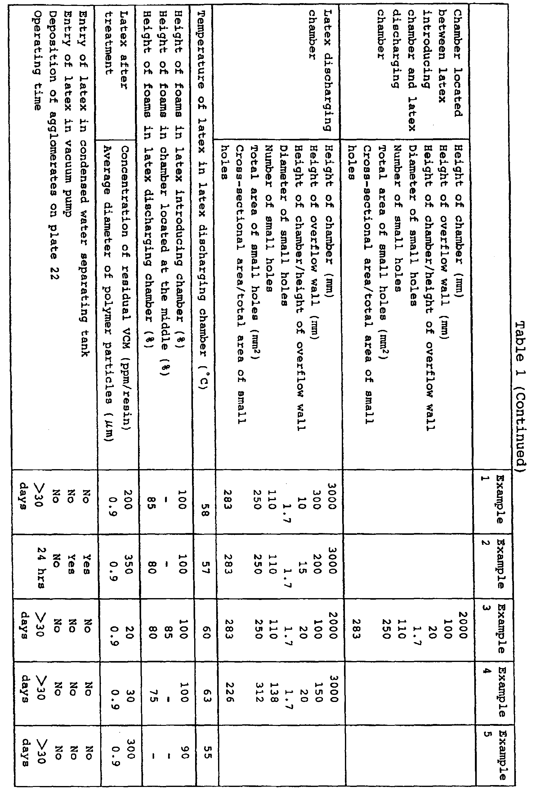
- Latex in latex supplying tank 1 contained 50.0 % by weight of water, 48.5 % by weight of solids mainly comprising vinyl chloride polymer, and 1.5 % by weight of unreacted vinyl chloride monomer. Average diameter of the vinyl chloride polymer particles was 0.9 ⁇ m. This polymer latex was supplied to such an apparatus as shown in Fig. 1 to remove unreacted monomer from the polymer latex.
- Average diameter of polymer particles in the polymer latex discharged from latex withdrawing tank 4 with latex discharging pump 5 was 0.9 ⁇ m without changing between before and after the monomer removing treatment. Coagula did not exist in the latex. Concentration of residual vinyl chloride monomer was 200 ppm on resin base.
- Latex used in Example 1 was treated in such an apparatus as shown in Fig. 1 in the same operational procedures as in the Example under the following apparatus specifications and operating conditions:
- Average diameter of polymer particles in the polymer latex discharged from latex withdrawing tank 4 with latex discharging pump 5 was 0.9 ⁇ m without changing between before and after the monomer removing treatment. Coagula did not exist in the latex. Concentration of residual vinyl chloride monomer was 350 ppm on resin base.
- Latex used in Example 1 was treated in an apparatus similar to that shown in Fig. 1 with the exception that the number of plates is 3, in the same operational procedures as in Example 1 under the following apparatus specifications and operating conditions:
- Average diameter of polymer particles in the polymer latex discharged from latex withdrawing tank 4 with latex discharging pump 5 was 0.9 ⁇ m without changing between before and after the monomer removing treatment. Coagula did not exist in the latex. Concentration of residual vinyl chloride monomer was 20 ppm on resin base.
- Latex used in Example 1 was treated in such an apparatus as shown in Fig. 1 in the same operational procedures as in the Example under the following apparatus specifications and operating conditions:
- Average diameter of polymer particles in the polymer latex discharged from latex withdrawing tank 4 with latex discharging pump 5 was 0.9 ⁇ m without changing between before and after the monomer removing treatment. Coagula did not exist in the latex. Concentration of residual vinyl chloride monomer was 30 ppm on resin base.
- Latex used in Example 1 was treated in an apparatus similar to that shown in Fig. 1 with the exception that the number of plate is 1, in the same operational procedures as in the Example under the following apparatus specifications and operating conditions:
- Average diameter of polymer particles in the polymer latex discharged from latex withdrawing tank 4 with latex discharging pump 5 was 0.9 ⁇ m without changing between before and after the monomer removing treatment. Coagula did not exist in the latex. Concentration of residual vinyl chloride monomer was 300 ppm on resin base.
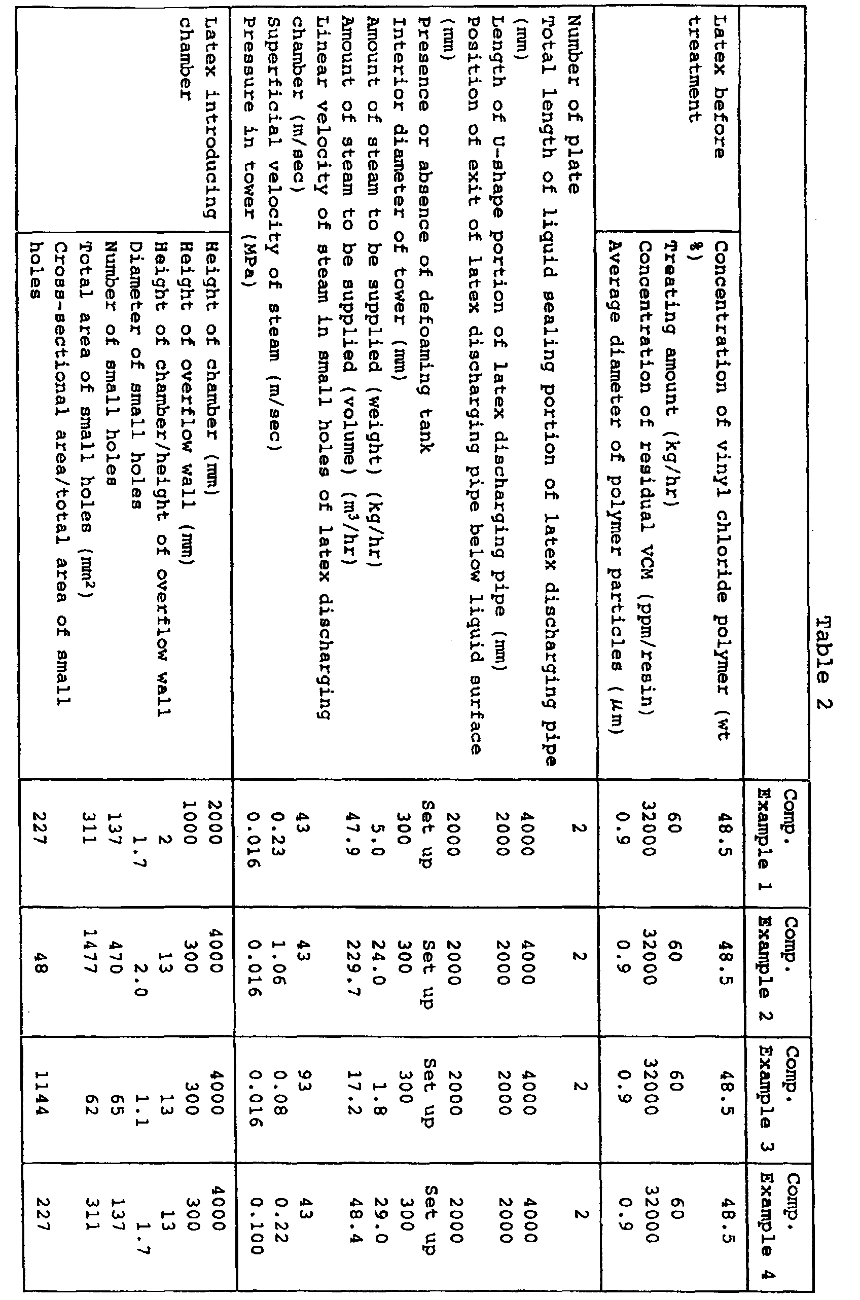
- Latex used in Example 1 was treated in such an apparatus as shown in Fig. 1 in the same operational procedures as in the Example under the following apparatus specifications and operating conditions:
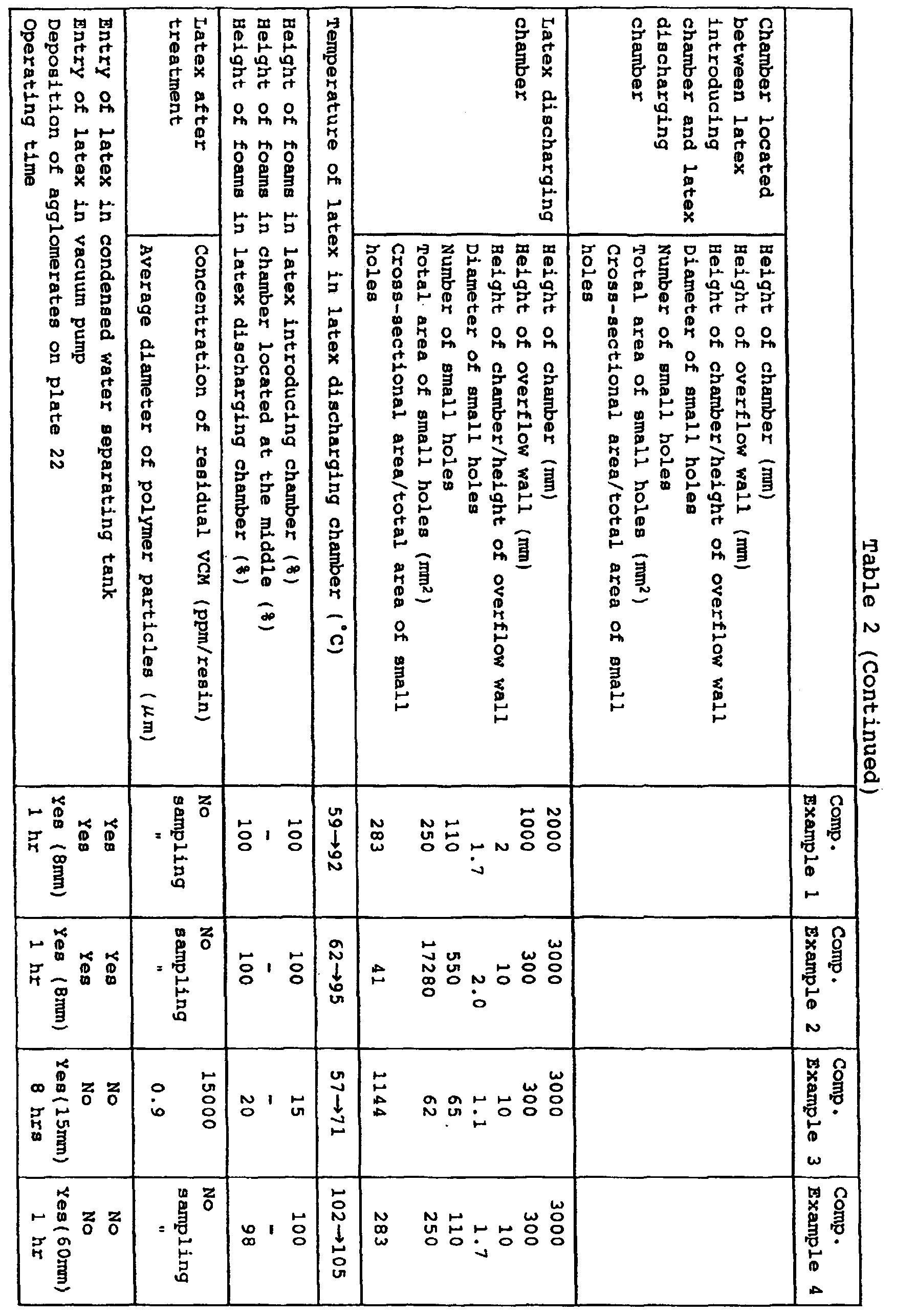
- latex discharging chamber 11 After termination of the operation, the inside of latex discharging chamber 11 was observed to find that coagula of a latex polymer were deposited on plate 22 to the extent of 8 mm thickness, and interior wall of the tower was covered with a thin film of the latex.
- Latex used in Example 1 was treated in such an apparatus as shown in Fig. 1 in the same operational procedures as in the Example under the following apparatus specifications and operating conditions:
- latex discharging chamber 11 After termination of the operation, the inside of latex discharging chamber 11 was observed to find that coagula of a latex polymer were deposited on plate 22 to the extent of 8 mm thickness, and interior wall of the tower was covered with a thin film of the latex.
- Latex used in Example 1 was treated in such an apparatus as shown in Fig. 1 in the same operational procedures as in the Example under the following apparatus specifications and operating conditions:
- Average diameter of polymer particles in the polymer latex discharged from latex withdrawing tank 4 with latex discharging pump 5 was 0.9 ⁇ m without changing between before and after the monomer removing treatment. Coagula did not exist in the latex. Concentration of residual vinyl chloride monomer was 15000 ppm on resin base.
- Latex used in Example 1 was treated in such an apparatus as shown in Fig. 1 in the same operational procedures as in the Example under the following apparatus specifications and operating conditions:
- latex discharging chamber 11 After termination of the operation, the inside of latex discharging chamber 11 was observed to find that clay-like coagula of a latex polymer were deposited on plate 22 to the extent of 60 mm thickness, and interior wall of the tower was covered with a thick film of the latex.
- the apparatus of the present invention When the apparatus of the present invention is used, unreacted monomer existing in a polymer latex can be removed at a high efficiency even when a defoaming agent is not used.
- the apparatus of the present invention can preferably be used for removing residual monomer from a vinyl chloride polymer latex having a high foaming or bubbling property.
Landscapes
- Chemical & Material Sciences (AREA)
- Chemical Kinetics & Catalysis (AREA)
- Health & Medical Sciences (AREA)
- Dispersion Chemistry (AREA)
- Medicinal Chemistry (AREA)
- Polymers & Plastics (AREA)
- Organic Chemistry (AREA)
- Toxicology (AREA)
- Addition Polymer Or Copolymer, Post-Treatments, Or Chemical Modifications (AREA)
Abstract
Description
and operating the apparatus under the conditions that the pressure in the chamber in which the latex is introduced is 0.04 to 0.07 MPa and that the total depth of the latex on each of the plates is 25 to 1500 mm.


(Accordingly, height of chamber/height of overflow wall was 2)
(Accordingly, height of chamber/height of overflow wall was 2)
(This is the amount of steam necessary to obtain the same linear speed as that of steam (43 m/sec) in small holes of the plate in the latex discharging chamber in Example 1 under a pressure of 0.1 MPa.)

Claims (17)
- An apparatus for removing unreacted monomer from a polymer latex containing the unreacted monomer which apparatus comprisinga cylindrical tower,one or more plates which have many small holes perforated therethrough and are provided in a vertical direction in the tower,partition walls and an overflow wall formed on each of the plates,one or more chambers formed on one or more of the plates with the plate being their bottom surface,a latex discharging port provided at one of the chambers at the very least,at least one latex introducing port provided at a position higher than the latex discharging port,a deaerating port provided at a position higher than the latex introducing port and connected to a pressure reducing pump provided outside the tower to reduce the pressure in the tower, anda steam introducing port provided below the plate which forms the bottom surface of the chamber at which the latex discharging port is provided,the chambers standing 3 to 300 times as high as the overflow wall, and the cross-sectional area of the tower at the position where any one of the plates is provided being 50 to 1000 times as large as the total area of the small holes perforated through the plate.
- The apparatus according to claim 1 wherein the tower comprises two or more plates; a latex discharging port provided at the chamber formed on the lowermost plate; at least one latex introducing port provided at the chamber formed on at least one of the plates at a position higher than the lowermost plate; and a downcomer for flowing down a latex therethrough from an upper plate to a lower plate.
- The apparatus according to claim 1 wherein the number of the plate provided in the tower is 1 to 4.
- The apparatus according to claim 1 wherein the total of the height of the overflow walls formed on each of the plates is 25 to 1500 mm.
- The apparatus according to claim 1 wherein defoaming means is provided between the deaerating port and the pressure reducing pump, and/or inside the tower.
- The apparatus according to claim 5 wherein the defoaming means is a device for adding a liquid containing a defoaming agent, steam ejecting device, foam crushing blade, defoaming plate, or cyclone.
- The apparatus according to claim 5 wherein the apparatus further comprises a line for introducing a defoamed latex from the defoaming means into the tower again.
- The apparatus according to claim 1 wherein the apparatus further comprises a latex discharging pipe connected to the latex discharging port, the latex discharging pipe having a liquid sealing portion.
- The apparatus according to claim 8 wherein the apparatus further comprises a latex withdrawing tank connected to the latex discharging port through the latex discharging pipe.
- The apparatus according to claim 8 wherein the cross-sectional area of the latex discharging pipe is 1/10 to 1/1000 of the cross-sectional area of the tower, and the total length of the liquid sealing portion is 500 to 5000 mm.
- The apparatus according to claim 10 wherein at least a part of the liquid sealing portion is formed by a U-shape sealing pipe.
- The apparatus according to claim 11 wherein another part of the liquid sealing portion is arranged such that the exit of the latex discharging pipe is positioned below the liquid surface of the latex stored in the latex withdrawing tank.
- The apparatus according to claim 5 wherein the defoaming means is provided between the uppermost plate in the tower and the deaerating port.
- A process for removing unreacted monomer from a polymer latex containing the unreacted monomer which process comprises using an apparatus comprisinga cylindrical tower,one or more plates which have many small holes perforated therethrough and are provided in a vertical direction in the tower,partition walls and an overflow wall formed on each of the plates,one or more chambers formed on one or more of the plates with the plate being their bottom surface,a latex discharging port provided at one of the chambers at the very least,at least one latex introducing port provided at a position higher than the latex discharging port,a deaerating port provided at a position higher than the latex introducing port and connected to a pressure reducing pump provided outside the tower to reduce the pressure in the tower, anda steam introducing port provided below the plate which forms the bottom surface of the chamber at which the latex discharging port is provided,the chambers standing 3 to 300 times as high as the overflow wall, and the cross-sectional area of the tower at the position where any one of the plates is provided being 50 to 1000 times as large as the total area of the small holes perforated through the plate,
and operating the apparatus under the conditions that the pressure in the chamber in which the latex is introduced is 0.04 to 0.07 MPa and that the total depth of the latex on each of the plates is 25 to 1500 mm. - The process according to claim 14 wherein the apparatus is operated under the condition that the temperature of the latex flowing on the plate positioned directly above the chamber at which the steam introducing port is provided is 30 to 90°C.
- The process according to claim 14 wherein the apparatus is operated under the condition that the linear velocity of the steam passing through the small holes perforated through the plate which forms the bottom surface of the chamber at which the latex discharging port is provided is 10 to 100 m/sec.
- The process according to claim 14 wherein the apparatus further comprises a latex discharging pipe connected to the latex discharging port, and the apparatus is operated under the condition that the flow speed of the latex in the latex discharging pipe is 0.01 to 5 m/sec.
Applications Claiming Priority (3)
| Application Number | Priority Date | Filing Date | Title |
|---|---|---|---|
| JP11516899 | 1999-04-22 | ||
| JP11516899 | 1999-04-22 | ||
| PCT/JP2000/002628 WO2000064950A1 (en) | 1999-04-22 | 2000-04-21 | Device and method for removing unreacted monomer from polymer latex |
Publications (2)
| Publication Number | Publication Date |
|---|---|
| EP1097947A1 true EP1097947A1 (en) | 2001-05-09 |
| EP1097947A4 EP1097947A4 (en) | 2003-03-19 |
Family
ID=14656036
Family Applications (1)
| Application Number | Title | Priority Date | Filing Date |
|---|---|---|---|
| EP00919147A Ceased EP1097947A4 (en) | 1999-04-22 | 2000-04-21 | DEVICE AND METHOD FOR EXTRACTION OF NON-REACTED MONOMER FROM A POLYMERIC LATEX |
Country Status (5)
| Country | Link |
|---|---|
| EP (1) | EP1097947A4 (en) |
| KR (1) | KR100429272B1 (en) |
| CN (1) | CN1137149C (en) |
| TW (1) | TW527368B (en) |
| WO (1) | WO2000064950A1 (en) |
Cited By (4)
| Publication number | Priority date | Publication date | Assignee | Title |
|---|---|---|---|---|
| CN105521628A (en) * | 2016-01-07 | 2016-04-27 | 永胜机械工业(昆山)有限公司 | Removing tower used in polyvinyl chloride resin production |
| US10570223B2 (en) | 2014-05-28 | 2020-02-25 | Lg Chem, Ltd. | Stripping apparatus |
| WO2021150509A1 (en) * | 2020-01-21 | 2021-07-29 | Exxonmobil Chemical Patents Inc. | Strand evaporator used for devolatilizing polymers |
| EP4043498A4 (en) * | 2020-04-24 | 2023-01-11 | LG Chem, Ltd. | POST-TREATMENT DEVICE |
Families Citing this family (9)
| Publication number | Priority date | Publication date | Assignee | Title |
|---|---|---|---|---|
| SE528996C2 (en) * | 2005-04-29 | 2007-04-03 | Alfa Laval Corp Ab | Process for deodorization, a bottom for plug flow, a column, a plant and the use of a deodorization plant |
| JP5572847B2 (en) | 2010-03-17 | 2014-08-20 | 株式会社Moresco | Cylinder liner and manufacturing method thereof |
| CN102120789B (en) * | 2010-07-12 | 2012-09-26 | 赛鼎工程有限公司 | Degassing technology in synthetic process of neoprene |
| CN103920311B (en) * | 2014-03-08 | 2015-10-28 | 天伟化工有限公司 | PVC paste resin removes the method containing VC gas in foam in producing |
| WO2015183006A1 (en) * | 2014-05-28 | 2015-12-03 | 주식회사 엘지화학 | Stripping apparatus |
| CN106693448A (en) * | 2015-08-03 | 2017-05-24 | 安徽华明制药有限公司 | Defoaming method used for preparation process of emulsifier |
| DE202017107262U1 (en) | 2017-11-29 | 2017-12-13 | Apex Mfg. Co., Ltd. | Anvil of a stapler |
| KR102727041B1 (en) * | 2020-06-22 | 2024-11-07 | 주식회사 엘지화학 | Vinyl chloride unreacted monomer recover method |
| JP7541406B1 (en) | 2023-09-14 | 2024-08-28 | 株式会社コスモテック | Distillation Treatment Equipment |
Family Cites Families (7)
| Publication number | Priority date | Publication date | Assignee | Title |
|---|---|---|---|---|
| JPS548693A (en) * | 1977-06-21 | 1979-01-23 | Chisso Corp | Removal of monomer from vinyl chloride resin slurry by steam treatment using improved plate column |
| DE2832972A1 (en) * | 1978-07-27 | 1980-02-07 | Wacker Chemie Gmbh | METHOD FOR PRESSURE AND RESIDUE DEGASSING OF A PVC-WATER MIXTURE IN THE POLYMERIZATION AUTOCLAVE AT THE HIGHEST POSSIBLE SEPARATION DEGREE OF THE TRANSMISSION IN A ADDITIONAL SEPARATOR AND RETURN OF THE TRANSMISSION TO THE RESTOURY |
| JPS5622305A (en) * | 1979-08-01 | 1981-03-02 | Chisso Corp | Monomer removal from vinyl chloride resin slurry by steaming and apparatus therefor |
| DE3200413A1 (en) * | 1982-01-09 | 1983-07-21 | Bayer Ag, 5090 Leverkusen | METHOD FOR DEMONOMERIZING POLYMER SLURRIES |
| JP3029075B2 (en) * | 1992-09-25 | 2000-04-04 | チッソ株式会社 | Method and apparatus for producing resin powder with low residual vinyl monomer content by steam treatment of vinyl chloride resin slurry |
| JP3709568B2 (en) * | 1994-02-07 | 2005-10-26 | チッソ株式会社 | Residual monomer removal treatment method and residual monomer removal treatment tower used therefor |
| JP3724012B2 (en) * | 1995-08-04 | 2005-12-07 | チッソ株式会社 | Residual monomer removal apparatus and residual monomer removal method using the same |
-
2000
- 2000-04-21 EP EP00919147A patent/EP1097947A4/en not_active Ceased
- 2000-04-21 CN CNB008009740A patent/CN1137149C/en not_active Expired - Lifetime
- 2000-04-21 KR KR10-2000-7014681A patent/KR100429272B1/en not_active Expired - Fee Related
- 2000-04-21 WO PCT/JP2000/002628 patent/WO2000064950A1/en not_active Ceased
- 2000-04-21 TW TW089107614A patent/TW527368B/en not_active IP Right Cessation
Cited By (7)
| Publication number | Priority date | Publication date | Assignee | Title |
|---|---|---|---|---|
| US10570223B2 (en) | 2014-05-28 | 2020-02-25 | Lg Chem, Ltd. | Stripping apparatus |
| CN105521628A (en) * | 2016-01-07 | 2016-04-27 | 永胜机械工业(昆山)有限公司 | Removing tower used in polyvinyl chloride resin production |
| WO2021150509A1 (en) * | 2020-01-21 | 2021-07-29 | Exxonmobil Chemical Patents Inc. | Strand evaporator used for devolatilizing polymers |
| CN114980988A (en) * | 2020-01-21 | 2022-08-30 | 埃克森美孚化学专利公司 | Chain evaporator for devolatilizing polymers |
| US11976154B2 (en) | 2020-01-21 | 2024-05-07 | ExxonMobil Engineering & Technology Company | Devolatilization apparatus and process |
| EP4043498A4 (en) * | 2020-04-24 | 2023-01-11 | LG Chem, Ltd. | POST-TREATMENT DEVICE |
| US12006392B2 (en) | 2020-04-24 | 2024-06-11 | Lg Chem, Ltd. | Post-processing apparatus |
Also Published As
| Publication number | Publication date |
|---|---|
| TW527368B (en) | 2003-04-11 |
| CN1310726A (en) | 2001-08-29 |
| EP1097947A4 (en) | 2003-03-19 |
| WO2000064950A1 (en) | 2000-11-02 |
| KR100429272B1 (en) | 2004-04-29 |
| CN1137149C (en) | 2004-02-04 |
| KR20010053137A (en) | 2001-06-25 |
Similar Documents
| Publication | Publication Date | Title |
|---|---|---|
| TWI381874B (en) | A static devolatilisation apparatus for a liquid containing polymers | |
| JPH07224109A (en) | Residual monomer removal treatment method and residual monomer removal treatment tower used therefor | |
| US2467769A (en) | Removal of volatile substances from aqueous dispersions of elastomeric materials | |
| US6211331B1 (en) | Polymer devolatilization apparatus | |
| US4483747A (en) | Monomer removal from the slurry of vinyl chloride resin with steam by using improved plate tower | |
| KR100429272B1 (en) | Device and method for removing unreacted monomer from polymer latex | |
| JP3724012B2 (en) | Residual monomer removal apparatus and residual monomer removal method using the same | |
| KR100505907B1 (en) | Methods and apparatus for removing residual monomers | |
| US4201628A (en) | Separation apparatus | |
| CA1152689A (en) | Process for removing monomer from vinyl chloride resin slurry by steam treatment and apparatus employed therefor | |
| PL107124B1 (en) | METHOD OF CONTINUOUS WATER TREATMENT OF POLYMERIDE BASED ON POLYCHLORIDE WITH GASES AND EQUIPMENT FOR CONTINUOUS TREATMENT OF POLYMERIUM SUSPENSION BASED ON POLYVERSIDE WITH POLYVERSIDE | |
| US4303479A (en) | Distillation separation method | |
| JPWO2000064950A1 (en) | Apparatus and method for removing unreacted monomer from polymer latex | |
| JPH09268206A (en) | Method for recovering low boiling point substance from polymer latex | |
| JP3029075B2 (en) | Method and apparatus for producing resin powder with low residual vinyl monomer content by steam treatment of vinyl chloride resin slurry | |
| US4328186A (en) | Recirculating polymerization method and apparatus with evaporative cooling | |
| CN215139822U (en) | A kind of butadiene anti-self-polymerization device | |
| JPH10338708A (en) | Apparatus for removing unreacted monomer from polyvinyl chloride-containing slurry and removal | |
| US3464967A (en) | Circulating solids dispersed in a liquid | |
| JP4257006B2 (en) | Method and apparatus for producing vinyl chloride paste resin latex | |
| EP4070868A1 (en) | Tray-type distillation apparatus | |
| EP4019105B1 (en) | Stripping device and stripping method | |
| JPH11100410A (en) | Method for recovering unreacted monomer from vinyl chloride polymer latex | |
| US4332924A (en) | Recirculating polymerization method and apparatus with evaporative cooling | |
| JPS59213711A (en) | Continuous conditioning of syrup |
Legal Events
| Date | Code | Title | Description |
|---|---|---|---|
| PUAI | Public reference made under article 153(3) epc to a published international application that has entered the european phase |
Free format text: ORIGINAL CODE: 0009012 |
|
| 17P | Request for examination filed |
Effective date: 20010313 |
|
| AK | Designated contracting states |
Kind code of ref document: A1 Designated state(s): AT BE CH CY DE DK ES FI FR GB GR IE IT LI LU MC NL PT SE |
|
| A4 | Supplementary search report drawn up and despatched |
Effective date: 20030204 |
|
| RIC1 | Information provided on ipc code assigned before grant |
Ipc: 7B 01D 3/20 B Ipc: 7B 01D 3/22 B Ipc: 7B 01D 3/38 B Ipc: 7B 01D 3/14 B Ipc: 7C 08F 6/00 B Ipc: 7B 01D 19/04 B Ipc: 7C 08F 6/24 A Ipc: 7B 01D 1/14 B Ipc: 7B 01D 19/02 B |
|
| RBV | Designated contracting states (corrected) |
Designated state(s): BE DE ES FR GB IT |
|
| RAP1 | Party data changed (applicant data changed or rights of an application transferred) |
Owner name: JNC CORPORATION |
|
| REG | Reference to a national code |
Ref country code: DE Ref legal event code: R003 |
|
| STAA | Information on the status of an ep patent application or granted ep patent |
Free format text: STATUS: THE APPLICATION HAS BEEN REFUSED |
|
| 18R | Application refused |
Effective date: 20110610 |