EP1097894A1 - A unit for generating discrete lengths of paper material from a continuous strip - Google Patents
A unit for generating discrete lengths of paper material from a continuous strip Download PDFInfo
- Publication number
- EP1097894A1 EP1097894A1 EP00830695A EP00830695A EP1097894A1 EP 1097894 A1 EP1097894 A1 EP 1097894A1 EP 00830695 A EP00830695 A EP 00830695A EP 00830695 A EP00830695 A EP 00830695A EP 1097894 A1 EP1097894 A1 EP 1097894A1
- Authority
- EP
- European Patent Office
- Prior art keywords
- strip
- tension
- cam
- unit
- diverter element
- Prior art date
- Legal status (The legal status is an assumption and is not a legal conclusion. Google has not performed a legal analysis and makes no representation as to the accuracy of the status listed.)
- Granted
Links
- 239000000463 material Substances 0.000 title claims description 14
- 238000005520 cutting process Methods 0.000 claims abstract description 24
- 230000005540 biological transmission Effects 0.000 claims description 13
- 230000033001 locomotion Effects 0.000 claims description 12
- 230000010355 oscillation Effects 0.000 claims description 2
- 235000019504 cigarettes Nutrition 0.000 abstract description 12
- 230000002093 peripheral effect Effects 0.000 description 8
- 238000004519 manufacturing process Methods 0.000 description 3
- 230000000694 effects Effects 0.000 description 2
- 239000000853 adhesive Substances 0.000 description 1
- 230000001070 adhesive effect Effects 0.000 description 1
- 230000000712 assembly Effects 0.000 description 1
- 238000000429 assembly Methods 0.000 description 1
- 230000002238 attenuated effect Effects 0.000 description 1
- 230000001747 exhibiting effect Effects 0.000 description 1
- 230000000717 retained effect Effects 0.000 description 1
- 238000000926 separation method Methods 0.000 description 1
- 239000000126 substance Substances 0.000 description 1
Images



Classifications
-
- A—HUMAN NECESSITIES
- A24—TOBACCO; CIGARS; CIGARETTES; SIMULATED SMOKING DEVICES; SMOKERS' REQUISITES
- A24C—MACHINES FOR MAKING CIGARS OR CIGARETTES
- A24C5/00—Making cigarettes; Making tipping materials for, or attaching filters or mouthpieces to, cigars or cigarettes
- A24C5/47—Attaching filters or mouthpieces to cigars or cigarettes, e.g. inserting filters into cigarettes or their mouthpieces
- A24C5/471—Attaching filters or mouthpieces to cigars or cigarettes, e.g. inserting filters into cigarettes or their mouthpieces by means of a connecting band
-
- B—PERFORMING OPERATIONS; TRANSPORTING
- B65—CONVEYING; PACKING; STORING; HANDLING THIN OR FILAMENTARY MATERIAL
- B65H—HANDLING THIN OR FILAMENTARY MATERIAL, e.g. SHEETS, WEBS, CABLES
- B65H23/00—Registering, tensioning, smoothing or guiding webs
- B65H23/04—Registering, tensioning, smoothing or guiding webs longitudinally
-
- B—PERFORMING OPERATIONS; TRANSPORTING
- B65—CONVEYING; PACKING; STORING; HANDLING THIN OR FILAMENTARY MATERIAL
- B65H—HANDLING THIN OR FILAMENTARY MATERIAL, e.g. SHEETS, WEBS, CABLES
- B65H35/00—Delivering articles from cutting or line-perforating machines; Article or web delivery apparatus incorporating cutting or line-perforating devices, e.g. adhesive tape dispensers
- B65H35/04—Delivering articles from cutting or line-perforating machines; Article or web delivery apparatus incorporating cutting or line-perforating devices, e.g. adhesive tape dispensers from or with transverse cutters or perforators
- B65H35/08—Delivering articles from cutting or line-perforating machines; Article or web delivery apparatus incorporating cutting or line-perforating devices, e.g. adhesive tape dispensers from or with transverse cutters or perforators from or with revolving, e.g. cylinder, cutters or perforators
-
- B—PERFORMING OPERATIONS; TRANSPORTING
- B65—CONVEYING; PACKING; STORING; HANDLING THIN OR FILAMENTARY MATERIAL
- B65H—HANDLING THIN OR FILAMENTARY MATERIAL, e.g. SHEETS, WEBS, CABLES
- B65H2404/00—Parts for transporting or guiding the handled material
- B65H2404/60—Other elements in face contact with handled material
- B65H2404/63—Oscillating, pivoting around an axis parallel to face of material, e.g. diverting means
-
- B—PERFORMING OPERATIONS; TRANSPORTING
- B65—CONVEYING; PACKING; STORING; HANDLING THIN OR FILAMENTARY MATERIAL
- B65H—HANDLING THIN OR FILAMENTARY MATERIAL, e.g. SHEETS, WEBS, CABLES
- B65H2404/00—Parts for transporting or guiding the handled material
- B65H2404/60—Other elements in face contact with handled material
- B65H2404/65—Other elements in face contact with handled material rotating around an axis parallel to face of material and perpendicular to transport direction, e.g. star wheel
- B65H2404/652—Other elements in face contact with handled material rotating around an axis parallel to face of material and perpendicular to transport direction, e.g. star wheel having two elements diametrically opposed
Definitions
- the present invention relates to a unit serving to generate discrete lengths of paper material from a continuous strip.
- the invention finds application to advantage in a cigarette manufacturing machine, and in particular the filter tip attachment of a cigarette maker, for the preparation of tipping papers from a decoiling roll of continuous strip material; indeed reference is made explicitly to such an application in the following specification albeit with no limitation in scope applied.
- Filter tipped cigarettes are fashioned generally by interposing a double length filter plug between two axially aligned sticks of cigarette rod, whereupon the three elements are joined by a band of gummed paper and the resulting assembly is cut in half to produce two single filter cigarettes.
- the tipping papers are obtained from a continuous strip of gummed material directed along a predetermined path toward a cutter device by which the strip is divided into discrete bands of prescribed length.
- the cutter device comprises two contrarotating rollers with mutually parallel axes of rotation, disposed tangentially one to another.
- One roller affords an aspirating surface against which the strip is held by suction and drawn forward, and both are equipped with relative blades equispaced angularly around the surface of revolution.
- each blade of the one roller will interact with corresponding blades of the other roller in such a way as to sever the strip along transverse lines, effecting a scissor type cut: accordingly, each blade of the one roller combines with a blade of the other roller to constitute scissor means by which a discrete length is cut progressively from the strip as the rollers rotate.
- One of the rollers and more exactly the suction roller, continues to retain each successive tipping paper on its peripheral face after the relative cut is completed and carries it thus into contact with a double cigarette assembly as described briefly above, made up of two cigarette sticks and a double filter plug.
- the tipping papers must be spaced apart at a suitable distance one from the next after being severed from the continuous strip; this is done by causing the suction roller to rotate at a peripheral velocity higher than the linear velocity at which the strip advances.
- US Patent 4,943,341 teaches the expedient of introducing a diverter element with a cyclical action preceding the cutter device in the direction followed by the strip, such as will vary the tension of the strip at a frequency coinciding with that of the cutting stroke.
- the object of the invention is to provide a unit for generating discrete lengths of paper material from a continuous strip, such as will remain free of the drawback described above.
- the stated object is realized in a unit according to the present invention for generating discrete lengths of paper material from a continuous strip, comprising cutting means by which the papers are severed singly and in succession from the strip at a predetermined cutting frequency, also feed means by which the strip is caused to advance along a predetermined path and in a predetermined direction at a first predetermined tension, and tensioning means interposed between the feed means and the cutting means of which the function is to vary the first predetermined tension of the strip cyclically and synchronously with the selfsame cutting means, characterized in that the tensioning means comprise a diverter element presenting at least a first and a second transmission member and designed to oscillate cyclically when in operation between two tensioning limit positions in which the at least first and second transmission members interact alternately with the strip in such a way that the strip is diverted and caused to assume the first tension, passing also through an intermediate position in which the strip is caused to assume a second tension slacker than the first tension, and completing each full oscillating cycle between the two limit positions
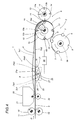
- 1 denotes a portion, in its entirety, of a cigarette making machine (not illustrated), and in particular the filter tip attachment of a cigarette maker, which includes a unit 2 for generating discrete lengths 3 of wrapping material, referred to simply as tipping papers, from a continuous strip 4 caused to decoil from a roll (not illustrated) and advance along a predetermined feed path P in a given direction D at a given tension and a given velocity.
- a unit 2 for generating discrete lengths 3 of wrapping material referred to simply as tipping papers
- the unit 2 comprises a cutter device 5 by which the papers 3 are severed from the continuous strip 4 and released onto a conveying roller 6 of familiar embodiment set in rotation anticlockwise about a respective axis 6a.
- the roller 6 is designed to convey assemblies 7 consisting each in two cigarette sticks separated one from the other by a double length filter plug, which are retained pneumatically in conventional manner by respective flutes 8 extending parallel to the straight line generators of the roller, and advanced by the roller 6 in a direction transverse to their own axes through a transfer station 9 at which a paper 3 is offered by the cutter device 5 to the external surface of each assembly 7.
- the cutter device 5 comprises a first suction roller 10 and a second roller 12, disposed substantially tangential one to the other and rotatable about respective axes 10a and 12a on respective shafts 10b and 12b.
- the continuous strip 4 is taken up by the suction roller 10 and advanced toward a cutting station 11 at which the first and second rollers 10 and 12 operate in conjunction in such a way as to divide up the strip into single papers 3.
- the diameter of the first roller 10 is larger than that of the second roller 12, and its peripheral velocity higher than the feed rate of the strip 4, whilst the peripheral surface carries a plurality of blades 13 spaced apart at identical angular distances, of which the respective cutting edges are substantially rectilinear and disposed skew in relation to the axis 10a of rotation.
- the second roller 12 which rotates at a peripheral velocity substantially equal to the feed rate of the strip 4, carries a plurality of substantially radial blades 14 distributed uniformly around the peripheral surface and disposed with their cutting edges substantially parallel to the axis 12a of the roller 12.
- the peripheral surface 15 of the first roller 10 is divided by the relative blades 13 into a plurality of aspirating sectors 16 each affording a plurality of suction holes 16a connected to a source of negative pressure (not illustrated, being conventional in embodiment).
- the unit 2 further comprises feed means 17 serving to supply the continuous strip 4 to the cutter device 5, and operating in conjunction with the first roller 10 in such a way as to advance the strip 4 along the feed path P.
- feed means 17 will be seen to comprise a pair of pinch rolls 18 and 19 disposed on either side of the feed path P followed by the strip 4.
- a gumming device 20 lying beyond the pinch rolls 18 and 19 in the feed direction is designed to coat the top face of the strip 4 thinly with an adhesive substance.
- the device 20 in question comprises a gumming roller 21 and a reaction roller 22 offered respectively to the opposite faces of the strip 4.
- the diverter element 24 comprises a cam 25 engaging the strip 4 in direct contact and mounted to a pivot 26 centred on an axis of rotation denoted A.
- the profile 27 of the cam 25 presents two lobes 28 and 29 constituting a first transmission member 30 and a second transmission member 31, respectively, by which the strip 4 is diverted.
- the cam 25 is invested cyclically with alternating rotary motion about the aforementioned axis A between a first angular limit position PA1 and a second angular limit position PA2.
- the tension of the strip 4 is the same in either one of the aforementioned limit positions PA1 and PA2, and it is in this taut condition Tn1 that the first part of the cut is made in the strip 4 by the relative device 5.
- the strip 4 For the second part of the cut to be made properly, as intimated in the preamble, the strip 4 needs to be at a tension Tn2 less than Tn1.
- the cam 25 is rotated to a position denoted PA0, indicated by a bold line in fig 1, in which there is substantially no diversion of the strip 4 from the feed path P as it advances relaxed between the gumming device 20 and the cutter device 5.
- the strip 4 is diverted from its normal trajectory by the cam 25, displaced from the feed path P by contact with the first transmission member 30 which coincides with the first lobe 28 of the selfsame cam 25.
- the cam 25 rotates anticlockwise, as viewed in fig 1, to assume the position denoted PA0 in which the strip 4 rides over a portion 27a of the cam profile 27 interconnecting the two lobes 28 and 29.
- strip tensioning means 23 comprise a diverter element 24 that consists in a rocker 33 supported by a pivot 40 and rotatable about an axis denoted B.
- the rocker 33 presents a first arm 33a and a second arm 33b engaging the strip 4 by way of respective contact rollers 35a and 35b.
- Each roller 35a and 35b is carried by a relative projecting end of the respective arm 33a and 33b, and freely rotatable.
- the two rollers 35a and 35b constitute respective first and second transmission members 30 and 31.
- the oscillating action of the rocker 33 is similar in every respect to that of the cam 25, in that it derives from power transmitted by the alternating drive means 32 in such a way as to produce rotary motion about the aforementioned axis B between two limit positions PA1 and PA2 in which the strip 4 is drawn taut.
- the rocker 33 moves through a cycle like that of the cam 25, starting for example from the position denoted PA1 in which the strip 4 is in the taut condition Tn1, by rotating anticlockwise through the position denoted PA0 to that denoted PA2, in which the strip 4 assumes the relaxed condition Tn2 and reassumes the taut condition Tn1, respectively.
- the direction of the rotary motion is inverted and the rocker 33 will rotate clockwise back through the intermediate position PA0 to the initial position PA1, in which the strip reassumes the relaxed condition Tn2 and the taut condition Tn1, respectively.
- the diverter element 24 of the tensioning means 23 is embodied as a crank 36, pivotable about an axis denoted C, of which a free end is forked and exhibits two arms 36a and 36b.
- the ends of the arms 36a and 36b carry respective rollers 47a and 47b offered in direct contact one to each face of the strip 4.
- Fig 4 illustrates a second embodiment of the cam 25 in which the portion 27a of the profile 27 between the two lobes 28 and 29 is of concave geometry.
- Such a solution might be adopted in order to limit the angular excursion of the diverter element 24 during the oscillating movement and thus minimize problems connected with the inertia of component parts in the element 24.
- the width of the strip dictates the need for a diverter element of appreciable dimensions, of which the mass, given the high operating speeds of the machines in question, will generate inertia forces that can be attenuated at least by limiting the angular travel of the diverter element 24.
- the diverter element 24 is designed as a double acting component characterized by alternating rotary motion, and therefore capable of stroking at half the operating frequency of the cutter device 5.
- the complete oscillating cycle includes two steps or positions whereby the strip 4 is drawn taut, alternated with two steps in which the strip 4 is relaxed and advances in contact with portions of the cam 25 exhibiting a shorter radial dimension.
- figs 5 to 9 show the operating sequence of one half the oscillating cycle of a diverter element 24 comprising a cam 37 pivotable about an axis of rotation denoted D.
- the profile 38 of the cam 37 exhibits three lobes 38a, 38b and 38c constituting respective transmission members 39a, 39b and 39c and disposed internally tangential to a common circumference of which the centre coincides with the axis D.
- the cam 37 in question is set in motion by alternating drive means not shown in figs 5 to 9, which illustrate only the cam 37 and the diverted strip 4, in the interests of clarity.
- the cam 37 rotates anticlockwise in the direction of the arrow (see fig 5) to assume the position denoted PB1 illustrated in fig 6, in which the strip 4 follows a linear trajectory along the feed path P advancing in the relaxed condition Tn2.
- the cam 37 takes up the position PB2 illustrated in fig 7, in which the strip 4 is tensioned in the taut condition Tn1 by the action of a second lobe 38b.
- Fig 8 illustrates a subsequent position PB3 of the cam 37 in which the strip 4 is once again in the relaxed condition Tn2 and rides over two lobes 38b and 38c positioned tangentially to the feed path P.
- the cam 37 makes one more anticlockwise rotation toward a limit position PB4 illustrated in fig 9, in which the strip 4 is again tensioned in the taut condition Tn1 through the agency of the remaining lobe 38c.
- the direction of rotation is inverted and the sequence repeated in reverse order, with the cam 37 moving in the direction of the arrow in fig 9 through the positions PB3, PB2 and PB1 described above to regain the starting position PB0.
- the oscillating cycle of the cam 37 is completed.
Landscapes
- Folding Of Thin Sheet-Like Materials, Special Discharging Devices, And Others (AREA)
- Manufacturing Of Cigar And Cigarette Tobacco (AREA)
- Auxiliary Devices For And Details Of Packaging Control (AREA)
- Making Paper Articles (AREA)
Abstract
Description
- The present invention relates to a unit serving to generate discrete lengths of paper material from a continuous strip.
- The invention finds application to advantage in a cigarette manufacturing machine, and in particular the filter tip attachment of a cigarette maker, for the preparation of tipping papers from a decoiling roll of continuous strip material; indeed reference is made explicitly to such an application in the following specification albeit with no limitation in scope applied.
- Filter tipped cigarettes are fashioned generally by interposing a double length filter plug between two axially aligned sticks of cigarette rod, whereupon the three elements are joined by a band of gummed paper and the resulting assembly is cut in half to produce two single filter cigarettes.
- Conventionally, the tipping papers are obtained from a continuous strip of gummed material directed along a predetermined path toward a cutter device by which the strip is divided into discrete bands of prescribed length.
- The cutter device comprises two contrarotating rollers with mutually parallel axes of rotation, disposed tangentially one to another. One roller affords an aspirating surface against which the strip is held by suction and drawn forward, and both are equipped with relative blades equispaced angularly around the surface of revolution.
- Typically, the blades of one roller will interact with corresponding blades of the other roller in such a way as to sever the strip along transverse lines, effecting a scissor type cut: accordingly, each blade of the one roller combines with a blade of the other roller to constitute scissor means by which a discrete length is cut progressively from the strip as the rollers rotate.
- One of the rollers, and more exactly the suction roller, continues to retain each successive tipping paper on its peripheral face after the relative cut is completed and carries it thus into contact with a double cigarette assembly as described briefly above, made up of two cigarette sticks and a double filter plug.
- For the jointing operation to be successful, the tipping papers must be spaced apart at a suitable distance one from the next after being severed from the continuous strip; this is done by causing the suction roller to rotate at a peripheral velocity higher than the linear velocity at which the strip advances.
- It follows therefore that in executing the single scissor cuts mentioned above to produce discrete bands, which are not separated immediately but will be distanced only after a given interval of time, the difference between the peripheral velocity of the suction roller and the linear feed rate of the strip does not allow a correct separation of the discrete papers from the strip. Because of the traction force generated by the suction roller, in effect, the strip is subject to a pulling action which during the course of each successive cutting operation becomes unsustainable for the portion of material growing narrower by degrees at the end of the cutting stroke, and induces excessive tensions in the as yet uncut edges of the material, with the result that the tipping paper tends to separate by tearing before the actual cutting action can be fully completed. The tipping papers separated in this manner are therefore unusable by reason of the irregularities discernible at the extremity of the cutting line.
- To the end of overcoming such drawbacks, US Patent 4,943,341 teaches the expedient of introducing a diverter element with a cyclical action preceding the cutter device in the direction followed by the strip, such as will vary the tension of the strip at a frequency coinciding with that of the cutting stroke.
- With strip feed rates becoming faster and faster, and the demand for increasingly higher production tempos, the diverter elements currently in use are now no longer able to match the cutting frequency of the relative machines.
- The object of the invention is to provide a unit for generating discrete lengths of paper material from a continuous strip, such as will remain free of the drawback described above.
- The stated object is realized in a unit according to the present invention for generating discrete lengths of paper material from a continuous strip, comprising cutting means by which the papers are severed singly and in succession from the strip at a predetermined cutting frequency, also feed means by which the strip is caused to advance along a predetermined path and in a predetermined direction at a first predetermined tension, and tensioning means interposed between the feed means and the cutting means of which the function is to vary the first predetermined tension of the strip cyclically and synchronously with the selfsame cutting means, characterized in that the tensioning means comprise a diverter element presenting at least a first and a second transmission member and designed to oscillate cyclically when in operation between two tensioning limit positions in which the at least first and second transmission members interact alternately with the strip in such a way that the strip is diverted and caused to assume the first tension, passing also through an intermediate position in which the strip is caused to assume a second tension slacker than the first tension, and completing each full oscillating cycle between the two limit positions at a frequency equivalent at least to half the cutting frequency of the cutting means.
- The invention will now be described in detail, by way of example, with the aid of the accompanying drawings, in which:
- fig 1 shows a portion of a cigarette manufacturing machine, illustrated schematically in a front view and equipped with a unit embodied according to the present invention for generating discrete lengths of paper material from a continuous strip;
- fig 2 illustrates a second embodiment of a unit for generating discrete lengths of paper material as in fig 1;
- fig 3 illustrates a further embodiment of a unit for generating discrete lengths of paper material as in fig 1;
- fig 4 illustrates a detail of fig 1, shown in a second embodiment;
- figs 5 to 9 illustrate the successive stages of an operating cycle pertinent to a further embodiment of the unit according to the present invention for generating discrete lengths of paper material from a continuous strip.
- Referring to figs 1...4 of the drawings, 1 denotes a portion, in its entirety, of a cigarette making machine (not illustrated), and in particular the filter tip attachment of a cigarette maker, which includes a
unit 2 for generatingdiscrete lengths 3 of wrapping material, referred to simply as tipping papers, from acontinuous strip 4 caused to decoil from a roll (not illustrated) and advance along a predetermined feed path P in a given direction D at a given tension and a given velocity. - As discernible from fig 1, the
unit 2 comprises acutter device 5 by which thepapers 3 are severed from thecontinuous strip 4 and released onto a conveyingroller 6 of familiar embodiment set in rotation anticlockwise about arespective axis 6a. Theroller 6 is designed to conveyassemblies 7 consisting each in two cigarette sticks separated one from the other by a double length filter plug, which are retained pneumatically in conventional manner byrespective flutes 8 extending parallel to the straight line generators of the roller, and advanced by theroller 6 in a direction transverse to their own axes through a transfer station 9 at which apaper 3 is offered by thecutter device 5 to the external surface of eachassembly 7. - In the example illustrated, the
cutter device 5 comprises afirst suction roller 10 and asecond roller 12, disposed substantially tangential one to the other and rotatable aboutrespective axes respective shafts - The
continuous strip 4 is taken up by thesuction roller 10 and advanced toward acutting station 11 at which the first andsecond rollers single papers 3. In the example illustrated, the diameter of thefirst roller 10 is larger than that of thesecond roller 12, and its peripheral velocity higher than the feed rate of thestrip 4, whilst the peripheral surface carries a plurality ofblades 13 spaced apart at identical angular distances, of which the respective cutting edges are substantially rectilinear and disposed skew in relation to theaxis 10a of rotation. Thesecond roller 12, which rotates at a peripheral velocity substantially equal to the feed rate of thestrip 4, carries a plurality of substantiallyradial blades 14 distributed uniformly around the peripheral surface and disposed with their cutting edges substantially parallel to theaxis 12a of theroller 12. Theperipheral surface 15 of thefirst roller 10 is divided by therelative blades 13 into a plurality ofaspirating sectors 16 each affording a plurality ofsuction holes 16a connected to a source of negative pressure (not illustrated, being conventional in embodiment). - The
unit 2 further comprises feed means 17 serving to supply thecontinuous strip 4 to thecutter device 5, and operating in conjunction with thefirst roller 10 in such a way as to advance thestrip 4 along the feed path P. - Observing figs 1 to 4, such feed means 17 will be seen to comprise a pair of
pinch rolls strip 4. - A
gumming device 20 lying beyond thepinch rolls strip 4 thinly with an adhesive substance. Thedevice 20 in question comprises agumming roller 21 and areaction roller 22 offered respectively to the opposite faces of thestrip 4. Also forming part of theunit 2 are means 23 by which to vary the tension of therunning strip 4, located between thegumming device 20 and thefirst roller 10; such tensioning means comprise a movingdiverter element 24 which by alternately distancing and returning thestrip 4 away from and back onto the feed path P produces a variation in the tension of thestrip 4 between a taut condition denoted Tn1 and a relaxed condition denoted Tn2. - As discernible from fig 1, the
diverter element 24 comprises acam 25 engaging thestrip 4 in direct contact and mounted to apivot 26 centred on an axis of rotation denoted A. - The
profile 27 of thecam 25 presents twolobes first transmission member 30 and asecond transmission member 31, respectively, by which thestrip 4 is diverted. - The
cam 25 is invested cyclically with alternating rotary motion about the aforementioned axis A between a first angular limit position PA1 and a second angular limit position PA2. - The alternating rotary motion in question will be transmitted to the
cam 25 synchronously with the movement of thecutter device 5 by drive means of conventional embodiment denoted schematically in the drawings by ablock 32. - The tension of the
strip 4 is the same in either one of the aforementioned limit positions PA1 and PA2, and it is in this taut condition Tn1 that the first part of the cut is made in thestrip 4 by therelative device 5. - For the second part of the cut to be made properly, as intimated in the preamble, the
strip 4 needs to be at a tension Tn2 less than Tn1. To obtain this relaxed condition Tn2 of thestrip 4, thecam 25 is rotated to a position denoted PA0, indicated by a bold line in fig 1, in which there is substantially no diversion of thestrip 4 from the feed path P as it advances relaxed between thegumming device 20 and thecutter device 5. - Following a complete cycle, starting for example from the limit position denoted PA1, the
strip 4 is diverted from its normal trajectory by thecam 25, displaced from the feed path P by contact with thefirst transmission member 30 which coincides with thefirst lobe 28 of theselfsame cam 25. In this position PA1, as mentioned previously, the first part of a cut is made to separate afirst paper 3. Thereafter thecam 25 rotates anticlockwise, as viewed in fig 1, to assume the position denoted PA0 in which thestrip 4 rides over aportion 27a of thecam profile 27 interconnecting the twolobes cam 25 in this position PA0, thestrip 4 is brought to the relaxed condition Tn2 and, once the cut has been completed to separate thefirst paper 3, thecam 25 rotates further in the anticlockwise direction to assume the position denoted PA2 in which thestrip 4 reassumes the taut condition Tn1 and thecutter device 5 begins the stroke that will separate asecond paper 3. At this point, the direction of rotation of thecam 25 will be reversed through the agency of the alternating drive means 32, with the result that thecam 25 rotates clockwise back to the passive position PA0 in which thestrip 4 is returned to the relaxed condition Tn2 and the cut is completed to separate thesecond paper 3. Thecam 25 is rotated further by the drive means 32, ultimately regaining the initial position PA1, and the cycle thus completed. Clearly enough, each full oscillating cycle of thecam 25 is completed at a frequency equivalent to half the frequency at which the tippingpapers 3 are separated by thecutter device 5. In short, twopapers 3 are cut from the strip during each cycle of thecam 25. - In the example of fig 2, strip tensioning means 23 comprise a
diverter element 24 that consists in arocker 33 supported by a pivot 40 and rotatable about an axis denoted B. - The
rocker 33 presents afirst arm 33a and asecond arm 33b engaging thestrip 4 by way ofrespective contact rollers roller respective arm lobes cam 25, the tworollers second transmission members rocker 33 is similar in every respect to that of thecam 25, in that it derives from power transmitted by the alternating drive means 32 in such a way as to produce rotary motion about the aforementioned axis B between two limit positions PA1 and PA2 in which thestrip 4 is drawn taut. - The
rocker 33 moves through a cycle like that of thecam 25, starting for example from the position denoted PA1 in which thestrip 4 is in the taut condition Tn1, by rotating anticlockwise through the position denoted PA0 to that denoted PA2, in which thestrip 4 assumes the relaxed condition Tn2 and reassumes the taut condition Tn1, respectively. On reaching the latter position PA2 ,the direction of the rotary motion is inverted and therocker 33 will rotate clockwise back through the intermediate position PA0 to the initial position PA1, in which the strip reassumes the relaxed condition Tn2 and the taut condition Tn1, respectively. - The return to the initial position PA1 marks the end of the cycle.
- In the example of fig 3, the
diverter element 24 of the tensioning means 23 is embodied as acrank 36, pivotable about an axis denoted C, of which a free end is forked and exhibits twoarms - The ends of the
arms respective rollers strip 4. - With this type of
diverter element 24 the action is desmodromic, inasmuch as thestrip 4 will not only be pushed away from its normal trajectory by therollers selfsame rollers gumming device 20 is placed to best advantage following thediverter element 24 along the feed direction, so that the effectiveness of the gumming operation will not be jeopardized by contact occurring subsequently between thestrip 4 and thecorresponding roller 47b. - Fig 4 illustrates a second embodiment of the
cam 25 in which theportion 27a of theprofile 27 between the twolobes diverter element 24 during the oscillating movement and thus minimize problems connected with the inertia of component parts in theelement 24. - In effect, the width of the strip dictates the need for a diverter element of appreciable dimensions, of which the mass, given the high operating speeds of the machines in question, will generate inertia forces that can be attenuated at least by limiting the angular travel of the
diverter element 24. Whichever of the embodiments described above may ultimately be adopted, thediverter element 24 is designed as a double acting component characterized by alternating rotary motion, and therefore capable of stroking at half the operating frequency of thecutter device 5. - As already stated, the complete oscillating cycle includes two steps or positions whereby the
strip 4 is drawn taut, alternated with two steps in which thestrip 4 is relaxed and advances in contact with portions of thecam 25 exhibiting a shorter radial dimension. - Still with the end in view of limiting the angular motion of the diverter element, a further solution is illustrated in figs 5 to 9. These figures show the operating sequence of one half the oscillating cycle of a
diverter element 24 comprising acam 37 pivotable about an axis of rotation denoted D. Theprofile 38 of thecam 37 exhibits threelobes respective transmission members - As in the embodiments already described, the
cam 37 in question is set in motion by alternating drive means not shown in figs 5 to 9, which illustrate only thecam 37 and the divertedstrip 4, in the interests of clarity. - Taking the start of the oscillating cycle for this
particular cam 37 to be the position denoted PB0 in fig 5, in which thestrip 4 is lifted by afirst lobe 38a from the feed path P and caused to assume the taut condition Tn1, the sequence is essentially the same as already described for the embodiments of figs 1 to 4, in that the taut condition Tn1 and the relaxed condition Tn2 of thestrip 4 correspond respectively to the first and second stages of the stroke with which thetipping paper 3 is separated by thecutter device 5. - Thereafter, the
cam 37 rotates anticlockwise in the direction of the arrow (see fig 5) to assume the position denoted PB1 illustrated in fig 6, in which thestrip 4 follows a linear trajectory along the feed path P advancing in the relaxed condition Tn2. Rotating further anticlockwise, thecam 37 takes up the position PB2 illustrated in fig 7, in which thestrip 4 is tensioned in the taut condition Tn1 by the action of asecond lobe 38b. - Fig 8 illustrates a subsequent position PB3 of the
cam 37 in which thestrip 4 is once again in the relaxed condition Tn2 and rides over twolobes cam 37 makes one more anticlockwise rotation toward a limit position PB4 illustrated in fig 9, in which thestrip 4 is again tensioned in the taut condition Tn1 through the agency of the remaininglobe 38c. At this point the direction of rotation is inverted and the sequence repeated in reverse order, with thecam 37 moving in the direction of the arrow in fig 9 through the positions PB3, PB2 and PB1 described above to regain the starting position PB0. On arrival at this same position PB0, the oscillating cycle of thecam 37 is completed. It will be evident from the foregoing description that when using adiverter element 24 with threetransmission members element 24 is equivalent to a third of the frequency with which thetipping papers 3 are separated from the strip by thecutter device 5. - It follows that the number of transmission members incorporated into the
diverter element 24 can be increased to "n", and the oscillating frequency of the diverter element consequently made equivalent to 1/n times the operating frequency of thecutter device 5. - Accordingly, and by adopting any one of the various embodiments described and illustrated, it becomes possible to obtain operating speeds higher than those obtainable hitherto without jeopardizing the smooth operation of the filter tip attachment and moreover reducing the mechanical stress to which the components of the
diverter element 24 are subjected at a given operating tempo.
Claims (7)
- A unit for generating discrete lengths of paper material from a continuous strip, comprising cutting means (5) by which the papers (3) are severed singly and in succession from the strip (4) at a predetermined cutting frequency, also feed means (17) by which the strip (4) is caused to advance along a predetermined path (P) and in a predetermined direction (D) at a first predetermined tension (Tn1), and tensioning means (23) interposed between the feed means (17) and the cutting means (5) of which the function is to vary the first predetermined tension of the strip (4) cyclically and synchronously with the selfsame cutting means (5), characterized
in that the tensioning means (23) comprise a diverter element (24) presenting at least a first and a second transmission member (30, 31) and designed to oscillate cyclically when in operation between two tensioning limit positions (PA1, PA2) in which the at least first and second transmission members (30, 31) interact alternately with the strip (4) in such a way that the strip is diverted and caused to assume the first tension (Tn1), passing also through an intermediate position (PA0) in which the strip (4) is caused to assume a second tension (Tn2) slacker than the first, and completing each full oscillating cycle between the two limit positions (PA1, PA2) at a frequency equivalent at least to half the cutting frequency of the cutting means (5). - A unit as in claim 1, wherein the diverter element (24) comprises a cam (25) of which the profile (27) presents two distinct lobes (28, 29) coinciding respectively with the first and second transmission members (30, 31), and of which the action consists in alternating rotary motion brought about between the two limit positions (PA1, PA2) in which the strip (4) assumes the first tension.
- A unit as in claim 2, wherein the profile (27) of the cam (25) includes a portion (27a) of concave geometry interconnecting the two lobes (28, 29).
- A unit as in claim 1, wherein the diverter element (24) comprises a cam (37) of which the profile (38) presents three distinct lobes (38a, 38b, 38c) coinciding respectively with first, second and third transmission members (39a, 39b, 39c), and of which the action consists in alternating rotary motion compassing three positions (PB0, PB2, PB4) in which the strip (4) assumes the first tension and two intermediate positions (PB1, PB3) in which the strip (4) assumes a second tension slacker than the first, brought about in such a way that each full cycle of oscillation between the two limit positions (PB0, PB4) is completed at a frequency equivalent to one third the operating frequency of the cutting means (5).
- A unit as in claim 1, wherein the diverter element (24) comprises a rocker (33) pivotable about the axis (B) of a relative fulcrum, embodied with equidistant first and second extremities (34a, 34b) offered in contact to the strip (4) and invested with alternating rotary motion about the selfsame axis (B) between the two limit positions (PA1, PA2) in which the strip (4) assumes the first tension.
- A unit as in claim 5, wherein each of the first and second extremities (34a, 34b) of the rocker (33) carries a respective roller (35a, 35b) engaging in contact with the strip (4).
- A unit as in claim 1, wherein the diverter element (24) comprises a crank (36) pivotable about the axis (C) of a relative fulcrum, of which at least the free end is forked and exhibits two arms (36a, 36b) carrying respective rollers (47a, 47b) offered in direct contact one to each of the opposite faces of the strip (4).
Applications Claiming Priority (2)
| Application Number | Priority Date | Filing Date | Title |
|---|---|---|---|
| ITBO990584 | 1999-11-02 | ||
| IT1999BO000584A IT1311116B1 (en) | 1999-11-02 | 1999-11-02 | UNIT FOR THE REALIZATION OF CARDBOARD MATERIALS TO OPEN FROM A CONTINUOUS TAPE. |
Publications (2)
| Publication Number | Publication Date |
|---|---|
| EP1097894A1 true EP1097894A1 (en) | 2001-05-09 |
| EP1097894B1 EP1097894B1 (en) | 2003-05-14 |
Family
ID=11344314
Family Applications (1)
| Application Number | Title | Priority Date | Filing Date |
|---|---|---|---|
| EP00830695A Expired - Lifetime EP1097894B1 (en) | 1999-11-02 | 2000-10-24 | A unit for generating discrete lengths of paper material from a continuous strip |
Country Status (5)
| Country | Link |
|---|---|
| EP (1) | EP1097894B1 (en) |
| CN (1) | CN1173650C (en) |
| DE (1) | DE60002651T2 (en) |
| ES (1) | ES2198271T3 (en) |
| IT (1) | IT1311116B1 (en) |
Cited By (8)
| Publication number | Priority date | Publication date | Assignee | Title |
|---|---|---|---|---|
| EP1410724A1 (en) * | 2002-10-17 | 2004-04-21 | G.D S.p.A. | A unit for preparing leaves of paper material |
| EP1584558A1 (en) * | 2004-04-08 | 2005-10-12 | G.D S.p.A. | A unit for feeding and cutting into lengths a strip of wrapping material |
| JP2014515939A (en) * | 2011-06-08 | 2014-07-07 | ジ・ディ・ソシエタ・ペル・アチオニ | Method for producing cigarette with filter and filter mounting machine |
| GB2531034A (en) * | 2014-10-08 | 2016-04-13 | British American Tobacco Investments Ltd | Adhesive applicator |
| IT201800001948A1 (en) * | 2018-01-30 | 2019-07-30 | Gd Spa | Machine and method for making wrapping bands for the tobacco industry |
| CN111096475A (en) * | 2019-11-21 | 2020-05-05 | 南京智晟达自动化科技有限公司 | Equipment capable of improving quality of cigarette mouthpiece and control method thereof |
| CN114920056A (en) * | 2022-05-25 | 2022-08-19 | 湖北中烟工业有限责任公司 | Separated tipping paper cutting slip compensation device |
| CN118401975A (en) * | 2021-10-15 | 2024-07-26 | 埃沃咖股份公司 | Stirring rod forming assembly for stirring rod distributor in beverage vending machine |
Families Citing this family (8)
| Publication number | Priority date | Publication date | Assignee | Title |
|---|---|---|---|---|
| DE10206323A1 (en) * | 2002-02-14 | 2003-08-28 | Will E C H Gmbh & Co | Support device for a material web |
| JP5976229B2 (en) * | 2012-10-22 | 2016-08-23 | ブリティッシュ アメリカン タバコ (インヴェストメンツ) リミテッドBritish American Tobacco (Investments) Limited | Cutting equipment for use in the tobacco industry |
| CN106006144A (en) * | 2016-07-13 | 2016-10-12 | 上海烟草机械有限责任公司 | Paper tape cutting device and operating method thereof |
| CN110103599B (en) * | 2019-04-30 | 2025-06-10 | 厦门汉印股份有限公司 | A printing sheet conveyor and printer |
| CN111908244A (en) * | 2020-06-15 | 2020-11-10 | 西安交通大学 | Device for staggered disconnection of resin-based fiber composite prepreg |
| CN112077897B (en) * | 2020-08-27 | 2022-05-27 | 湖北冠昌胶粘科技有限公司 | Novel but continuous processing's polymer film guillootine |
| CN116135757B (en) * | 2021-11-18 | 2026-02-13 | 上海烟草集团有限责任公司 | A tension roller assembly and a cutting compensation device for aluminum foil in tobacco equipment. |
| CN119018684B (en) * | 2024-10-22 | 2026-03-06 | 浙江中烟工业有限责任公司 | Intermittent tensioning, conveying and cutting device and method for lining paper |
Citations (3)
| Publication number | Priority date | Publication date | Assignee | Title |
|---|---|---|---|---|
| US2957450A (en) * | 1956-12-04 | 1960-10-25 | American Mach & Foundry | Filter tip machine |
| US4943341A (en) * | 1982-07-14 | 1990-07-24 | G. D. Societa Per Azioni | Device with contrarotating knives for severing filter cigarette uniting bands from webs in automatic filter tipping machines |
| US5054346A (en) * | 1988-06-11 | 1991-10-08 | Korber Ag | Apparatus for repeatedly severing running webs of tipping paper and the like |
-
1999
- 1999-11-02 IT IT1999BO000584A patent/IT1311116B1/en active
-
2000
- 2000-10-24 DE DE60002651T patent/DE60002651T2/en not_active Expired - Fee Related
- 2000-10-24 ES ES00830695T patent/ES2198271T3/en not_active Expired - Lifetime
- 2000-10-24 EP EP00830695A patent/EP1097894B1/en not_active Expired - Lifetime
- 2000-11-01 CN CNB001319469A patent/CN1173650C/en not_active Expired - Fee Related
Patent Citations (3)
| Publication number | Priority date | Publication date | Assignee | Title |
|---|---|---|---|---|
| US2957450A (en) * | 1956-12-04 | 1960-10-25 | American Mach & Foundry | Filter tip machine |
| US4943341A (en) * | 1982-07-14 | 1990-07-24 | G. D. Societa Per Azioni | Device with contrarotating knives for severing filter cigarette uniting bands from webs in automatic filter tipping machines |
| US5054346A (en) * | 1988-06-11 | 1991-10-08 | Korber Ag | Apparatus for repeatedly severing running webs of tipping paper and the like |
Cited By (13)
| Publication number | Priority date | Publication date | Assignee | Title |
|---|---|---|---|---|
| EP1410724A1 (en) * | 2002-10-17 | 2004-04-21 | G.D S.p.A. | A unit for preparing leaves of paper material |
| US7162940B2 (en) | 2002-10-17 | 2007-01-16 | G.D S.P.A. | Unit for preparing leaves of paper material |
| CN1308212C (en) * | 2002-10-17 | 2007-04-04 | 吉地股份公司 | Equipment for preparing paper sheet |
| EP1584558A1 (en) * | 2004-04-08 | 2005-10-12 | G.D S.p.A. | A unit for feeding and cutting into lengths a strip of wrapping material |
| US7437982B2 (en) | 2004-04-08 | 2008-10-21 | G.D S.P.A. | Unit for feeding and cutting into lengths a strip of wrapping material |
| CN100478256C (en) * | 2004-04-08 | 2009-04-15 | 吉地股份公司 | A unit for feeding and cutting into lengths a strip of wrapping material |
| JP2014515939A (en) * | 2011-06-08 | 2014-07-07 | ジ・ディ・ソシエタ・ペル・アチオニ | Method for producing cigarette with filter and filter mounting machine |
| GB2531034A (en) * | 2014-10-08 | 2016-04-13 | British American Tobacco Investments Ltd | Adhesive applicator |
| IT201800001948A1 (en) * | 2018-01-30 | 2019-07-30 | Gd Spa | Machine and method for making wrapping bands for the tobacco industry |
| EP3516969A1 (en) * | 2018-01-30 | 2019-07-31 | G.D. S.p.A | Machine and method for making plug wraps for the tobacco industry |
| CN111096475A (en) * | 2019-11-21 | 2020-05-05 | 南京智晟达自动化科技有限公司 | Equipment capable of improving quality of cigarette mouthpiece and control method thereof |
| CN118401975A (en) * | 2021-10-15 | 2024-07-26 | 埃沃咖股份公司 | Stirring rod forming assembly for stirring rod distributor in beverage vending machine |
| CN114920056A (en) * | 2022-05-25 | 2022-08-19 | 湖北中烟工业有限责任公司 | Separated tipping paper cutting slip compensation device |
Also Published As
| Publication number | Publication date |
|---|---|
| CN1173650C (en) | 2004-11-03 |
| CN1302569A (en) | 2001-07-11 |
| ITBO990584A0 (en) | 1999-11-02 |
| ES2198271T3 (en) | 2004-02-01 |
| EP1097894B1 (en) | 2003-05-14 |
| DE60002651D1 (en) | 2003-06-18 |
| DE60002651T2 (en) | 2004-02-19 |
| ITBO990584A1 (en) | 2001-05-02 |
| IT1311116B1 (en) | 2002-02-28 |
Similar Documents
| Publication | Publication Date | Title |
|---|---|---|
| EP1097894B1 (en) | A unit for generating discrete lengths of paper material from a continuous strip | |
| US6634269B2 (en) | Apparatus and method for associating cut sheet sections with a moving carrier web | |
| US4856725A (en) | Web winding machine and method | |
| US4962897A (en) | Web winding machine and method | |
| US4723724A (en) | Web winding machine and method | |
| US3992244A (en) | Tape applicating and severing assembly | |
| AU613071B2 (en) | Method and apparatus for applying elastic band onto moving web | |
| EP0212879B1 (en) | Apparatus for adjusting a cigarette having variable smoking characteristics | |
| US4360398A (en) | Method for applying elastic bands to webs | |
| EP1726278A1 (en) | Method and machine for folding and finishing training pant diapers | |
| JPH0236092A (en) | Cutter | |
| CN101185530A (en) | A machine for manufacturing composite filter tip | |
| GB2123737A (en) | Device for severing webs by contrarotating knives | |
| EP1410724A1 (en) | A unit for preparing leaves of paper material | |
| US3506017A (en) | Machine for wrapping uniting bands around rod-shaped articles | |
| JP6048846B2 (en) | Method for producing cigarette with filter and filter mounting machine | |
| EP1358808B1 (en) | A curling device | |
| RU2145177C1 (en) | Wrapping apparatus | |
| US5443681A (en) | Device for splicing ribbons of small transverse dimensions automatically | |
| US4716707A (en) | Apparatus for shrink-wrapping articles with handles | |
| US3267820A (en) | Manufacture of mouthpiece for cigarettes | |
| US20050223861A1 (en) | Unit for feeding and cutting into lengths a strip of wrapping material | |
| US4209956A (en) | Forming overlapped wrappers | |
| SU1181519A3 (en) | Device for attaching filters to tobacco stems | |
| EP1883319B1 (en) | A unit for transferring sticks of rod material used to manufacture tobacco products |
Legal Events
| Date | Code | Title | Description |
|---|---|---|---|
| PUAI | Public reference made under article 153(3) epc to a published international application that has entered the european phase |
Free format text: ORIGINAL CODE: 0009012 |
|
| AK | Designated contracting states |
Kind code of ref document: A1 Designated state(s): DE ES FR GB IT |
|
| AX | Request for extension of the european patent |
Free format text: AL;LT;LV;MK;RO;SI |
|
| 17P | Request for examination filed |
Effective date: 20010716 |
|
| 17Q | First examination report despatched |
Effective date: 20011119 |
|
| AKX | Designation fees paid |
Free format text: DE ES FR GB IT |
|
| GRAG | Despatch of communication of intention to grant |
Free format text: ORIGINAL CODE: EPIDOS AGRA |
|
| GRAG | Despatch of communication of intention to grant |
Free format text: ORIGINAL CODE: EPIDOS AGRA |
|
| GRAH | Despatch of communication of intention to grant a patent |
Free format text: ORIGINAL CODE: EPIDOS IGRA |
|
| RAP1 | Party data changed (applicant data changed or rights of an application transferred) |
Owner name: G.D S.P.A. |
|
| GRAH | Despatch of communication of intention to grant a patent |
Free format text: ORIGINAL CODE: EPIDOS IGRA |
|
| GRAA | (expected) grant |
Free format text: ORIGINAL CODE: 0009210 |
|
| AK | Designated contracting states |
Designated state(s): DE ES FR GB IT |
|
| REG | Reference to a national code |
Ref country code: GB Ref legal event code: FG4D |
|
| REF | Corresponds to: |
Ref document number: 60002651 Country of ref document: DE Date of ref document: 20030618 Kind code of ref document: P |
|
| REG | Reference to a national code |
Ref country code: ES Ref legal event code: FG2A Ref document number: 2198271 Country of ref document: ES Kind code of ref document: T3 |
|
| ET | Fr: translation filed | ||
| PLBE | No opposition filed within time limit |
Free format text: ORIGINAL CODE: 0009261 |
|
| STAA | Information on the status of an ep patent application or granted ep patent |
Free format text: STATUS: NO OPPOSITION FILED WITHIN TIME LIMIT |
|
| 26N | No opposition filed |
Effective date: 20040217 |
|
| PGFP | Annual fee paid to national office [announced via postgrant information from national office to epo] |
Ref country code: IT Payment date: 20061031 Year of fee payment: 7 |
|
| PGFP | Annual fee paid to national office [announced via postgrant information from national office to epo] |
Ref country code: DE Payment date: 20071130 Year of fee payment: 8 Ref country code: ES Payment date: 20071026 Year of fee payment: 8 |
|
| PGFP | Annual fee paid to national office [announced via postgrant information from national office to epo] |
Ref country code: FR Payment date: 20071017 Year of fee payment: 8 Ref country code: GB Payment date: 20071029 Year of fee payment: 8 |
|
| GBPC | Gb: european patent ceased through non-payment of renewal fee |
Effective date: 20081024 |
|
| REG | Reference to a national code |
Ref country code: FR Ref legal event code: ST Effective date: 20090630 |
|
| PG25 | Lapsed in a contracting state [announced via postgrant information from national office to epo] |
Ref country code: DE Free format text: LAPSE BECAUSE OF NON-PAYMENT OF DUE FEES Effective date: 20090501 Ref country code: IT Free format text: LAPSE BECAUSE OF NON-PAYMENT OF DUE FEES Effective date: 20071024 |
|
| PG25 | Lapsed in a contracting state [announced via postgrant information from national office to epo] |
Ref country code: FR Free format text: LAPSE BECAUSE OF NON-PAYMENT OF DUE FEES Effective date: 20081031 |
|
| PG25 | Lapsed in a contracting state [announced via postgrant information from national office to epo] |
Ref country code: GB Free format text: LAPSE BECAUSE OF NON-PAYMENT OF DUE FEES Effective date: 20081024 |
|
| REG | Reference to a national code |
Ref country code: ES Ref legal event code: FD2A Effective date: 20081025 |
|
| PG25 | Lapsed in a contracting state [announced via postgrant information from national office to epo] |
Ref country code: ES Free format text: LAPSE BECAUSE OF NON-PAYMENT OF DUE FEES Effective date: 20081025 |