EP1097889A2 - Bewegungssteuerungsverfahren für Hochgeschwindigkeitskuvertiervorrichtung oder andere Postmaschine - Google Patents
Bewegungssteuerungsverfahren für Hochgeschwindigkeitskuvertiervorrichtung oder andere Postmaschine Download PDFInfo
- Publication number
- EP1097889A2 EP1097889A2 EP00123494A EP00123494A EP1097889A2 EP 1097889 A2 EP1097889 A2 EP 1097889A2 EP 00123494 A EP00123494 A EP 00123494A EP 00123494 A EP00123494 A EP 00123494A EP 1097889 A2 EP1097889 A2 EP 1097889A2
- Authority
- EP
- European Patent Office
- Prior art keywords
- axis
- motion
- velocity
- segment
- controlled
- Prior art date
- Legal status (The legal status is an assumption and is not a legal conclusion. Google has not performed a legal analysis and makes no representation as to the accuracy of the status listed.)
- Withdrawn
Links
- 238000000034 method Methods 0.000 title claims abstract description 55
- 238000013507 mapping Methods 0.000 claims abstract description 27
- 238000006073 displacement reaction Methods 0.000 claims abstract description 26
- 230000001133 acceleration Effects 0.000 claims abstract description 18
- 230000036461 convulsion Effects 0.000 claims abstract description 9
- 230000008569 process Effects 0.000 abstract description 28
- 230000010354 integration Effects 0.000 abstract description 7
- 230000008859 change Effects 0.000 abstract description 2
- 238000010586 diagram Methods 0.000 description 8
- 230000000875 corresponding effect Effects 0.000 description 7
- 230000001276 controlling effect Effects 0.000 description 3
- 238000011144 upstream manufacturing Methods 0.000 description 3
- 230000009286 beneficial effect Effects 0.000 description 2
- 230000008901 benefit Effects 0.000 description 2
- 239000010410 layer Substances 0.000 description 2
- 238000012986 modification Methods 0.000 description 2
- 230000004048 modification Effects 0.000 description 2
- 230000007704 transition Effects 0.000 description 2
- 239000011247 coating layer Substances 0.000 description 1
- 230000001143 conditioned effect Effects 0.000 description 1
- 230000002596 correlated effect Effects 0.000 description 1
- 230000003247 decreasing effect Effects 0.000 description 1
- 238000002347 injection Methods 0.000 description 1
- 239000007924 injection Substances 0.000 description 1
- 230000003287 optical effect Effects 0.000 description 1
- 230000011664 signaling Effects 0.000 description 1
- 230000001360 synchronised effect Effects 0.000 description 1
- 238000004804 winding Methods 0.000 description 1
Images




Classifications
-
- B—PERFORMING OPERATIONS; TRANSPORTING
- B65—CONVEYING; PACKING; STORING; HANDLING THIN OR FILAMENTARY MATERIAL
- B65H—HANDLING THIN OR FILAMENTARY MATERIAL, e.g. SHEETS, WEBS, CABLES
- B65H5/00—Feeding articles separated from piles; Feeding articles to machines
- B65H5/34—Varying the phase of feed relative to the receiving machine
-
- G—PHYSICS
- G07—CHECKING-DEVICES
- G07B—TICKET-ISSUING APPARATUS; FARE-REGISTERING APPARATUS; FRANKING APPARATUS
- G07B17/00—Franking apparatus
- G07B17/00459—Details relating to mailpieces in a franking system
- G07B17/00467—Transporting mailpieces
-
- B—PERFORMING OPERATIONS; TRANSPORTING
- B65—CONVEYING; PACKING; STORING; HANDLING THIN OR FILAMENTARY MATERIAL
- B65H—HANDLING THIN OR FILAMENTARY MATERIAL, e.g. SHEETS, WEBS, CABLES
- B65H2511/00—Dimensions; Position; Numbers; Identification; Occurrences
- B65H2511/20—Location in space
- B65H2511/21—Angle
- B65H2511/212—Rotary position
-
- B—PERFORMING OPERATIONS; TRANSPORTING
- B65—CONVEYING; PACKING; STORING; HANDLING THIN OR FILAMENTARY MATERIAL
- B65H—HANDLING THIN OR FILAMENTARY MATERIAL, e.g. SHEETS, WEBS, CABLES
- B65H2511/00—Dimensions; Position; Numbers; Identification; Occurrences
- B65H2511/50—Occurence
- B65H2511/51—Presence
- B65H2511/514—Particular portion of element
-
- B—PERFORMING OPERATIONS; TRANSPORTING
- B65—CONVEYING; PACKING; STORING; HANDLING THIN OR FILAMENTARY MATERIAL
- B65H—HANDLING THIN OR FILAMENTARY MATERIAL, e.g. SHEETS, WEBS, CABLES
- B65H2513/00—Dynamic entities; Timing aspects
- B65H2513/20—Acceleration or deceleration
-
- B—PERFORMING OPERATIONS; TRANSPORTING
- B65—CONVEYING; PACKING; STORING; HANDLING THIN OR FILAMENTARY MATERIAL
- B65H—HANDLING THIN OR FILAMENTARY MATERIAL, e.g. SHEETS, WEBS, CABLES
- B65H2513/00—Dynamic entities; Timing aspects
- B65H2513/50—Timing
- B65H2513/51—Sequence of process
-
- B—PERFORMING OPERATIONS; TRANSPORTING
- B65—CONVEYING; PACKING; STORING; HANDLING THIN OR FILAMENTARY MATERIAL
- B65H—HANDLING THIN OR FILAMENTARY MATERIAL, e.g. SHEETS, WEBS, CABLES
- B65H2557/00—Means for control not provided for in groups B65H2551/00 - B65H2555/00
- B65H2557/20—Calculating means; Controlling methods
- B65H2557/24—Calculating methods; Mathematic models
-
- B—PERFORMING OPERATIONS; TRANSPORTING
- B65—CONVEYING; PACKING; STORING; HANDLING THIN OR FILAMENTARY MATERIAL
- B65H—HANDLING THIN OR FILAMENTARY MATERIAL, e.g. SHEETS, WEBS, CABLES
- B65H2701/00—Handled material; Storage means
- B65H2701/10—Handled articles or webs
- B65H2701/19—Specific article or web
- B65H2701/1916—Envelopes and articles of mail
-
- G—PHYSICS
- G07—CHECKING-DEVICES
- G07B—TICKET-ISSUING APPARATUS; FARE-REGISTERING APPARATUS; FRANKING APPARATUS
- G07B17/00—Franking apparatus
- G07B17/00459—Details relating to mailpieces in a franking system
- G07B17/00508—Printing or attaching on mailpieces
- G07B2017/00516—Details of printing apparatus
- G07B2017/00524—Printheads
- G07B2017/0054—Thermal printhead
Definitions
- the present invention pertains to the field of sheet feeding. More particularly, the present invention pertains to controlling the motion of sheets through a sheet handling device, such as a mailing machine, a postage meter, an envelope printer or inserter, and including a high-speed inserter.
- a sheet handling device such as a mailing machine, a postage meter, an envelope printer or inserter, and including a high-speed inserter.
- a typical sheet or envelope handling device includes various structures, motors and sensors.
- a typical envelope handling device includes an envelope feeding structure for feeding an envelope or a batch of envelopes in singular fashion in a downstream path of travel to a work station.
- Typical envelope handling devices employ ejection rollers or ejection belts operating at a constant speed, or at some speed that varies as a function of time, speeds chosen so as to avoid envelope collisions and noise, and also to avoid so-called bounce-back from a wall when an envelope strikes a wall designed to stop its forward travel and cause it to drop onto the top of a stack.
- speed chosen so as to avoid envelope collisions and noise, and also to avoid so-called bounce-back from a wall when an envelope strikes a wall designed to stop its forward travel and cause it to drop onto the top of a stack.
- bounce-back Depending on how the envelope moves through the device, more or less noise and bounce-back will result. It is beneficial to control to a fine degree the motion of a sheet or envelope handling device so as to keep noise
- a motion profile consists of a series of segments, each segment having a duration and each corresponding to a state of motion of an axis of a motor ultimately responsible for imparting motion to a sheet or envelope.
- a motor may have an axis that in rotating pulls a sheet through part of a mailing system at a certain speed, after accelerating at a specified acceleration as a function of time, and concluding with some specified deceleration as a function of time. If the sheet does not slip, then the motion of the sheet can be correlated precisely with the motion of the axis of the motor: the sheet moves through the mailing system with a speed that is exactly equal to the speed of rotation of the part of the axis in contact with the sheet, i.e. usually the surface of a belt driven by the axis.
- commands are sometimes sent to a motor to impart motion to a sheet, for a series of time segments, based simply on the assumption that the motion of the axis of the motor causing the motion of the sheet can be equated to the motion of the sheet.
- a sheet in a sheet handling device will slip so that the motion of the axis does not necessarily indicate the motion of a sheet (or envelope). Then the motion of an axis of a motor can be conditioned based on receiving commands from sensors used to detect the presence of the sheet as it moves through the sheet handling device.
- commands are sent based on a sheet not slipping, or based on information from sensors, the commands can be sent without regard to, i.e. independent of, the motion of the axis of any other motor. It is also possible, however, to send commands to a motor based on the motion of other motors.
- What is needed is a methodology for providing motion profiles that express the required motion of axes of motors for causing a sheet to move through a mailing system in a desired way, a methodology that incorporates, for a given segment of the motion profile, a basis for specifying a particular kind of motion (the kind independent of the motion of other axes in the mailing system, and the kind that depend on the motion of other axes), and that sets out rules by which to construct each possible kind of segment.
- the present invention provides a method for creating a motion profile used in controlling motion of an axis of a motor in a mailing machine, the motion profile expressing the motion of the axis in terms of a motion variable having a value depending on time, the motion profile consisting of a finite number of segments, the motion repeating after the motion prescribed in the finite number of segments is performed, the motion prescribed only at predetermined values of time separated by a loop closure period and measured from a starting time corresponding to a trigger event, the method calling for one of four methods of generating a segment of a profile, depending on whether, for the segment, either absolute positional synchronism with another axis, or a quick step (moving from one position to another by first accelerating and then decelerating) is needed.
- the method calls for determining position and velocity, for the segment, after each loop closure period by forward integrating over time from starting values of jerk, acceleration, velocity and position. If absolute mechanical positional synchronism with respect to another axis is required and a quick step move is not needed, the method calls for determining position after each loop closure period by performing a displacement mapping using as an input either the commanded or actual position of a reference axis, where the displacement mapping is a non-parabolic function of the commanded or actual position of the reference axis, i.e. does not involve the actual or commanded position of the reference axis to the second power.
- the method calls for determining position after each loop closure period based on a parabolic velocity equation, having as inputs a step time and a step value. Finally, if a quick step is needed and absolute mechanical positional synchronism with respect to motion of another motor is required, the method calls for determining position after each loop closure period by a displacement mapping using as an input either the commanded or actual position of a reference axis, where the displacement mapping is a parabolic function of the commanded or actual position of the reference axis.
- the present invention will be described after first describing a mailing apparatus, namely a thermal postage meter, for which the methodology of the present invention could be used to generate motion profiles.
- a thermal postage meter is to be understood as simply one kind of application which the methodology of the present invention could be applied to determine the motion profile.
- the methodology of the present invention is intended for any kind of mailing apparatus, and the advantage of applying the present methodology increases as the complexity of the mailing apparatus increases, so that its application to a high-speed inserting machine, for example, is especially beneficial.
- a thermal postage meter 11 includes a base 13 and a substantially vertical registration wall 17.
- the registration wall 17 and the base 13 are rigid structures, each providing a suitable framework for mounting and supporting various other components.
- Fixably mounted to the registration wall 17 and to the base 13 is a substantially horizontal deck 15.
- a thermal print head 19, a trailing edge sensor 27 and a leading edge sensor 29 are fixably mounted to the registration wall 17.
- a thermal ribbon cassette 21 containing a supply of thermal ribbon TR which has a backing layer and an ink coating layer.
- the thermal ribbon TR is unwound from a supply reel 401 and feeds along a defined path such that the backing layer comes into contact with the thermal print head 19 before being collected on a take-up reel 402.
- a backing roller 31 Rotatively mounted to the registration wall 17 is a backing roller 31.
- An envelope 25 having a leading edge 24 and a trailing edge 26 is shown positioned on the deck 15 and travels along a defined path from left to right as indicated by an arrow "A".
- the deck 15 includes an opening 22 and deck recess 23, which are generally aligned underneath the thermal print head 19 and the backing roller 31.
- a print and eject roller drive assembly 33 is generally located in the deck recess 23 such that a print roller 107 is opposite the thermal print head 19 and an eject roller 113 is opposite the backing roller 31.
- the axes of the print roller 107 and eject roller 113 are substantially parallel and transverse to the direction of envelope travel "A".
- the deck recess 23 is sufficiently large to accommodate the drive assembly 33.
- nip i.e. a converging of two rotating surfaces that pulls a sheet, in this case an envelope, through a mailing apparatus.
- the nip 380 between the print roller 107 and the thermal print head 19 is commonly referred to as a workstation or print station, where actual printing of a postal indicia on the envelope 25 is performed.
- the nip between the ejection roller 113 and the backing roller 31 is commonly referred to as the exit of the thermal meter 11.
- the eject roller 113 is located downstream from the print head 19.
- the control system 51 includes a programmable micro-controller 53 of any suitable conventional design, which uses a bus 55 to communicate with a motor controller 57, a sensor controller 59, and a thermal print head controller 61.
- the motor controller 57, sensor controller 59, and thermal print head controller 61 are each of any suitable conventional design.
- the motor controller 57 uses a motor bus 63 to communicate with a drive motor 65, a crank motor 67 and a take-up reel motor 68.
- the drive motor 65 and crank motor 67 are suitably designed stepper motors.
- the sensor controller 59 uses a sensor bus 71 to communicate with the trailing edge sensor 27, the leading edge sensor 29, a home position sensor 73, and a supply reel sensor 69.
- the thermal print head controller 61 uses a thermal print head bus 75 to communicate with the thermal print head 19.
- the trailing edge sensor 27, leading edge sensor 29, home position sensor 73 and supply reel sensor 69 are suitably designed optical sensors.
- the trailing edge sensor 27 is located a known distance upstream from the ejection roller 113.
- a speed versus time profile having segments 541-544, or motion profile is shown along with a corresponding state diagram having states 41-44, the motion profile for controlling the motion of an envelope through the thermal postage meter 11, by providing commands to its motors.
- the envelope 25 is accelerated until the trailing edge sensor 27 senses the trailing edge 26. Therefore, the length of the envelope is a factor that determines the peak speed of the envelope 25 in its progress through the thermal postage meter 11, the peak speed being achieved simultaneous with the trailing edge sensor 27 detecting the trailing edge 26.
- the leading edge sensor 29 and the trailing edge sensor 27 are suitably positioned relative to the deck 15 so as to detect the presence of the envelope 25.
- the leading edge sensor 29 is positioned downstream from the print roller 107, in the direction of envelope travel "A", but upstream from the drive shaft 101.
- the leading edge sensor 29 indicates to the micro-controller 53 when a leading edge 24 of the envelope 25 blocks the leading edge sensor 29.
- the trailing edge sensor 27 is positioned upstream from the print roller 107.
- the trailing edge sensor 27 indicates to the micro controller 53 when a trailing edge 26 of the envelope 25 is detected.
- the detecting of trailing edge 26 is an example of an "event" in the progress of the envelope 25 through the thermal postage meter 11. and on the occurrence of this event 553, the micro-controller 53, using the peak speed and the known distance from the trailing edge sensor 27 to the ejection roller 113, sends command signals to the motors of the thermal postage meter so as to provide a constant deceleration.
- the envelope is at a desired speed 571.
- the desired speed is selected based on various factors and objectives, including avoiding collisions, ensuring proper stacking of the envelopes in a later stacking device (not shown), reducing unwanted bounce-back, and reducing unwanted noise. Other factors include the weight of the envelope. It is therefore important that a motion profile be tailored to each kind of envelope and each configuration of the thermal postage meter with respect to any follow-on stacker.
- the drive assembly 33 includes the drive shaft 101, which is rotatively mounted to extend between the registration wall 17 and deck recess 23.
- the drive shaft 101 is located below and parallel to the deck 15. Additionally, the drive shaft 101 is aligned to be transverse to the direction of envelope travel "A".
- Rotatively mounted to the drive shaft 101 is a drive housing 103, which is a generally U-shaped bracket with suitable frame work for attaching various shafts, springs and gears.
- the deck recess 23 is sufficiently large and free from obstructions to allow the drive housing 103 to rotate or pivot freely about the drive shaft 101.
- Rotatively mounted to the drive housing 103 is a print roller shaft 105 and an eject roller shaft 111.
- Fixably mounted to the print roller shaft 105 is the print roller 107 and a print roller gear 109.
- Fixably mounted to the eject roller shaft 111 is the eject roller 113 and an eject roller gear 115.
- drive housing 103 behaves in a seesaw-like fashion, pivoting about the drive shaft 101 with the print roller 107 on one end of the drive housing 103, and the eject roller 113 on the other end of the drive housing 103.
- the drive motor 65 is connected to the print roller 107 and the eject roller 113 by a print roller gear train and an eject roller gear train, respectively.
- the drive motor 65 rotates both the print roller 107 and the eject roller 113.
- crank assembly generally located in the deck recess 23 and below the drive assembly 33.
- the crank assembly is under the control of micro-controller 53 and is primarily responsible from repositioning the drive housing 103 between the home, print and eject positions.
- the thermal postage meter 11 remains at idle, with the drive assembly 33 and the crank assembly 201 in the home position, until the operator or the envelope feed system advances the envelope 25 sufficiently along the deck 15 so that the leading edge 24 of envelope 25 is detected by the leading edge sensor 29.
- What is of interest for illustrating the present invention concerns only what happens to the envelope as it is ejected from the thermal print meter.
- the micro-controller 53 stops the drive motor 65 from rotating, and instructs the crank motor 67 to reposition the drive housing 103 from the print position to the eject position. While the drive housing 103 is being repositioned, the envelope 25 remains stationary on the deck 15 in the print station. As the drive housing 103 enters the eject position, the ejection roller 113 compresses the envelope 25 against the backing roller 31. Then the micro-controller 53 instructs the drive motor 65 to rotate, which in turn causes the eject roller 113 to rotate, and thus feed the envelope 25 out of the thermal meter 11.
- the micro-controller 53 may employ different speed versus time profiles to feed the envelope 25 out of the thermal meter 11. It is the methodology used to generate these speed profiles that is the subject of the present invention.
- a state diagram having states 41-44 is shown corresponding to the motion profile having segments 541-544.
- a state diagram generally, indicates a series of states of motion of an axis under the control of a motor, and each state corresponds to a segment of a motion profile.
- the motion profile having the (speed versus time) segments 541-544, and the corresponding states 41-44 of the state diagram are associated with the motion of the axis 111 of the eject roller 113, geared to the drive shaft 101, the motion resulting from commands to the drive motor 65 (Figs 1 and 2).
- a first state 41 the motor 65 is idle.
- power is provided to the windings of the motor 65.
- the drive motor is provided with power in such a way as to cause acceleration of axis 111 so that the eject roller 113 rotates with increasing (and later decreasing) speed, and thus feeds the envelope 25 out of the thermal meter 11.
- the envelope 25 is fed out with increasing speed until the trailing edge sensor 27 senses the trailing edge 26 of the envelope 25, prompting a commands to the motor 65 to cause the axis 111 to enter a state 44 of deceleration.
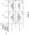
- a motion profile by which a motion profile is to be provided, is shown as including four processes 141-144 by which to determine a segment of a motion profile, one or another of the processes 141-144 to be used depending on the answers "Yes” 149 or “No” 150 to a first query 146, "Need a quick step?”; and also depending on the answers "Yes” 147 or “No” 148 to a second query 145, "Need absolute positional synchronism?"
- a quick step is a transition segment, as described above.
- Absolute positional synchronism of an axis is the synchronized motion of the axis with respect to the motion of some other axis.
- a process 141 of parabolic displacement mapping is performed when a quick step is needed, and absolute positional synchronism is also needed.
- the methodology calls for a process 142 performing displacement mapping.
- the methodology calls for performing a process 143 of mapping using a parabolic velocity equation.
- the methodology calls for performing a process 144 of forward integration.
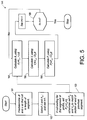
- the process 144 of performing forward integration to generate a segment of a motion profile is shown as including a first step 161 of predetermining a time increment At and a number n of such time increments so that n ⁇ t is the length of the segment for which the process of forward integration is to be performed.
- a value of so-called jerk i.e. acceleration per unit time, and also starting acceleration are selected, and a counter i is initialized.
- the value of jerk and starting acceleration are inputs to the process. Only one value of jerk is used throughout a segment, and if it is zero, the acceleration does not change from its starting value.
- a next step 163 the initial position and velocity are set to zero in the case that the segment is a first segment in a motion profile. Otherwise, the initial position and velocity for the segment are selected to match the motion at the end of the previous segment. It is also possible for other starting values of position of velocity to be used for a segment.
- a next step 164 the acceleration is calculated for each new interval of time At, based on the acceleration from the previous interval and based on the constant value of jerk.
- each new acceleration is used to calculate the velocity for each new time interval, also using as an input the velocity from the previous time interval.
- the position is calculated for each new interval time, using as input the velocity for that interval time and the position from the previous interval time.
- the counter i is incremented, and in a follow-up step 168, the counter is compared to the number of intervals in the segment, and if the number of intervals so far calculated exceeds the number of intervals in the segment, then the process of generating the segment is stopped.
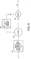
- the overall process of constructing a motion profile i.e. of constructing each segment of a motion profile, is shown as including a process 201 of inputting parameters (such as starting values of position, velocity and acceleration, and a value to be used for jerk), thereby placing the axis of the motor being controlled (to cause a desired motion of an envelope or sheet) in a state 202 labeled "State X".
- the overall process checks whether an event has occurred, as indicated in a decision block 203 labeled "Event?".
- the event of interest is whether a counter has exceeded a predetermined limit, namely the number of intervals in the segment.
- the process continues until, for example, a sensor detects a leading or trailing edge of an envelope or sheet, regardless of the value of a counter.
- a process 204 is performing in which the counter is incremented, and the profile is performed, i.e. the speed for a next time interval in the segment of the motion profile is determined, leading again to the decision block 203 checking for the occurrence of the event that would prompt beginning a new segment of a motion profile, or, equivalently, causing another state of motion of the axis whose motion is being controlled.
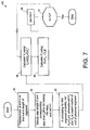
- the process 142 of performing a displacement mapping is indicated as beginning with a step 171 of picking a reference axis; the objective of this process is to determine the position of the axis to be controlled with respect to the reference axis, and thereby provide absolute positional synchronism.
- a function fthat accomplishes the displacement mapping is determined; the function/ displacement mapping relates the position of the axis to be controlled to the actual or commanded position of the reference axis.
- the reference axis has a high inertia or a high friction loading, it is preferable to use actual position so that the displacement relationships between the reference axis and the axis to be controlled are maintained even when the reference axis is not following its commanded profile exactly. If the reference axis has a lower inertia or a lower friction loading and is susceptible to outside disturbances, it is sometimes preferable to use commanded position so that the disturbances are not mapped to the axis to be controlled.
- a counter is initialized in a next step 174. Then in a next step 175, the actual commanded position of the reference axis is provided or calculated; and in a next step 176, the position of the axis to be controlled is calculated based on the actual commanded position of the reference axis, using the predetermined function/ displacement mapping f . In the next step 177, the counter is incremented; and in a next step 178, the process 142 determines whether an event has occurred prompting the beginning of a new segment of the motion profile.
- the process 142 of calculating the position, based on the displacement mapping, for a new value of the counter is performed, repeatedly, until the event occurs that is the basis for having the axis to be controlled undergo a new motion, indicated as a new state in a state diagram.
- the process 143 of providing a segment of a motion profile, as a parabolic velocity curve is shown to include a first step 81 of predetermining a time interval ⁇ t and number n of time intervals so that n ⁇ t is equal in values to the length of the segment.
- a step length S is specified, a corresponding step time (time for making the step) is also specified, and a counter is set to an initial value.
- initial values for the position and velocity are set, based on whether the segment of the motion profile is a first segment or a later segment in the motion profile. The position and velocity may be matched to the values of the end of a previous segment, if the current segment is preceded by a previous segment.
- a next step 84 for each subsequent value of the counter, the velocity is determined based on an equation that is parabolic in the counter (the value of the corresponding to a particular time interval).
- the position of the axis to be controlled is calculated based on the velocity calculated from the parabolic velocity equation, and based on the position in the previous interval.
- the interval is incremented, and in a subsequent step 87, it is compared to the number of intervals in the segment. If the counter has exceeded the number of intervals in the segment, the process is stopped. Otherwise the next velocity is calculated in a step 84, and so on.
- the process 141 of performing a parabolic displacement mapping is shown to include a first step 91 of picking a reference axis, followed by a step 92 of predetermining a displacement mapping (indicated as function f p ) that is parabolic in the actual or commanded position of the reference axis, i.e. in the expression for the function, the actual or commanded position occurs raised to the second power, as well as possibly the first power.
- a displacement mapping indicated as function f p
- a counter is initialized, and for each value of the counter, beginning with the initial value, first the commanded actual position of the reference axis is provided, and then the commanded position of the axis to be controlled is determined, based on the parabolic displacement mapping using as an input the actual or commanded position of the reference axis.
- the counter is incremented, and in a next step 98, the process determines whether an event has occurred signaling the end of the segment, and if so, the process 141 of determining the segment of the motion profile is stopped.
Landscapes
- Engineering & Computer Science (AREA)
- Mechanical Engineering (AREA)
- Physics & Mathematics (AREA)
- General Physics & Mathematics (AREA)
- Controlling Sheets Or Webs (AREA)
- Making Paper Articles (AREA)
- Bending Of Plates, Rods, And Pipes (AREA)
- Control Of Position Or Direction (AREA)
Applications Claiming Priority (2)
| Application Number | Priority Date | Filing Date | Title |
|---|---|---|---|
| US434553 | 1999-11-08 | ||
| US09/434,553 US6301522B1 (en) | 1999-11-08 | 1999-11-08 | Motion control methodology for a high-speed inserting machine or other mailing apparatus |
Publications (2)
| Publication Number | Publication Date |
|---|---|
| EP1097889A2 true EP1097889A2 (de) | 2001-05-09 |
| EP1097889A3 EP1097889A3 (de) | 2003-05-14 |
Family
ID=23724699
Family Applications (1)
| Application Number | Title | Priority Date | Filing Date |
|---|---|---|---|
| EP00123494A Withdrawn EP1097889A3 (de) | 1999-11-08 | 2000-11-08 | Bewegungssteuerungsverfahren für Hochgeschwindigkeitskuvertiervorrichtung oder andere Postmaschine |
Country Status (3)
| Country | Link |
|---|---|
| US (1) | US6301522B1 (de) |
| EP (1) | EP1097889A3 (de) |
| CA (1) | CA2325179A1 (de) |
Cited By (1)
| Publication number | Priority date | Publication date | Assignee | Title |
|---|---|---|---|---|
| US7232122B2 (en) * | 2003-03-14 | 2007-06-19 | Pitney Bowes Inc. | Jam detection method and system for an inserter |
Families Citing this family (5)
| Publication number | Priority date | Publication date | Assignee | Title |
|---|---|---|---|---|
| US6418357B1 (en) * | 2000-08-28 | 2002-07-09 | Pitney Bowes Inc. | Method for synchronizing an envelope inserter |
| US6690993B2 (en) * | 2000-10-12 | 2004-02-10 | R. Foulke Development Company, Llc | Reticle storage system |
| US6607190B1 (en) * | 2001-12-14 | 2003-08-19 | Pitney Bowes Inc. | Apparatus for providing gap control for a high-speed check feeder |
| US6893175B2 (en) * | 2003-09-30 | 2005-05-17 | Pitney Bowes Inc. | Method and system for high speed digital metering |
| US20060156876A1 (en) * | 2005-01-19 | 2006-07-20 | Pitney Bowes Incorporated | Motion control system and method for a high speed inserter input |
Family Cites Families (5)
| Publication number | Priority date | Publication date | Assignee | Title |
|---|---|---|---|---|
| US4449196A (en) * | 1979-04-27 | 1984-05-15 | Pritchard Eric K | Data processing system for multi-precision arithmetic |
| US4630210A (en) * | 1984-10-04 | 1986-12-16 | Pitney Bowes Inc. | Microprocessor controlled d.c. motor for controlling a load |
| US4988935A (en) * | 1989-05-24 | 1991-01-29 | Universal Instruments Corporation | Advanced digital motion control |
| US5521627A (en) * | 1994-10-28 | 1996-05-28 | Pitney Bowes Inc. | Thermal printer |
| US6601364B2 (en) * | 1999-08-30 | 2003-08-05 | Pitney Bowes Inc. | Method and device for synchronizing motion for insert feeders in an insertion system |
-
1999
- 1999-11-08 US US09/434,553 patent/US6301522B1/en not_active Expired - Fee Related
-
2000
- 2000-11-07 CA CA002325179A patent/CA2325179A1/en not_active Abandoned
- 2000-11-08 EP EP00123494A patent/EP1097889A3/de not_active Withdrawn
Cited By (1)
| Publication number | Priority date | Publication date | Assignee | Title |
|---|---|---|---|---|
| US7232122B2 (en) * | 2003-03-14 | 2007-06-19 | Pitney Bowes Inc. | Jam detection method and system for an inserter |
Also Published As
| Publication number | Publication date |
|---|---|
| US6301522B1 (en) | 2001-10-09 |
| EP1097889A3 (de) | 2003-05-14 |
| CA2325179A1 (en) | 2001-05-08 |
Similar Documents
| Publication | Publication Date | Title |
|---|---|---|
| EP0615212B1 (de) | Verfahren zur Postverarbeitung mit hoher Geschwindigkeit | |
| US5286317A (en) | Rotary die cutting mechanism | |
| JPS59230933A (ja) | 紙葉層を作業周期に即応して次位加工機に移送するための方法及び装置 | |
| EP1433733A2 (de) | Fexibles Speicherfördersystem zum Anordnen von gesammelten Dokumenten | |
| US6301522B1 (en) | Motion control methodology for a high-speed inserting machine or other mailing apparatus | |
| US5000727A (en) | Servo driven draw roll for bag machine | |
| US5560595A (en) | Envelope ejection speed control system and method | |
| US5464142A (en) | Web bursting machine | |
| US6877739B2 (en) | Vertical stacker input method and apparatus | |
| EP1080946B1 (de) | Verfahren und Vorrichtung zur Synchronisation der Bewegung der Dokumentzuführvorrichtung einer Kuvertiermashine | |
| US6418357B1 (en) | Method for synchronizing an envelope inserter | |
| EP0462421B1 (de) | Regler zur automatischen Steuerung des Arbeitszyklusses eines Falzmessers | |
| US4775087A (en) | Arrangement for the automatic control of the step-by-step advance of a foil sheet | |
| US5968307A (en) | Apparatus for affixing cards to a moving web | |
| US6959923B2 (en) | Method and device for improving stacker conveyor speed in a mail stacker | |
| JPH04215918A (ja) | 包装機械への材料ウエブの供給方法及びその装置 | |
| JPH09235056A (ja) | 帯状シート供給装置 | |
| EP0109799B1 (de) | Ausdehnungssteuerung in einer Laminiervorrichtung | |
| CN224118525U (zh) | 一种基于多电机驱动的激光打印机系统 | |
| US6499733B1 (en) | Method and apparatus for feeding sheet material into a printer or copier | |
| US20070181737A1 (en) | Tape extracting unit | |
| US5735443A (en) | Single part burster | |
| JP3919114B2 (ja) | 丁合機に搭載される給紙装置とその制御装置 | |
| JP2003106430A (ja) | バックラッシュ誤差削減装置 | |
| EP1022246A2 (de) | Verfahren und Apparat zur Lärmreduzierung in einer Falzmaschine |
Legal Events
| Date | Code | Title | Description |
|---|---|---|---|
| PUAI | Public reference made under article 153(3) epc to a published international application that has entered the european phase |
Free format text: ORIGINAL CODE: 0009012 |
|
| AK | Designated contracting states |
Kind code of ref document: A2 Designated state(s): AT BE CH CY DE DK ES FI FR GB GR IE IT LI LU MC NL PT SE TR |
|
| AX | Request for extension of the european patent |
Free format text: AL;LT;LV;MK;RO;SI |
|
| PUAL | Search report despatched |
Free format text: ORIGINAL CODE: 0009013 |
|
| AK | Designated contracting states |
Designated state(s): AT BE CH CY DE DK ES FI FR GB GR IE IT LI LU MC NL PT SE TR |
|
| AX | Request for extension of the european patent |
Extension state: AL LT LV MK RO SI |
|
| RIC1 | Information provided on ipc code assigned before grant |
Ipc: 7G 07B 17/00 B Ipc: 7B 65H 7/18 B Ipc: 7B 65H 7/20 A |
|
| STAA | Information on the status of an ep patent application or granted ep patent |
Free format text: STATUS: THE APPLICATION HAS BEEN WITHDRAWN |
|
| 18W | Application withdrawn |
Effective date: 20031028 |