EP1097823A1 - Jante destinée à recevoir un anneau de soutien - Google Patents
Jante destinée à recevoir un anneau de soutien Download PDFInfo
- Publication number
- EP1097823A1 EP1097823A1 EP00122630A EP00122630A EP1097823A1 EP 1097823 A1 EP1097823 A1 EP 1097823A1 EP 00122630 A EP00122630 A EP 00122630A EP 00122630 A EP00122630 A EP 00122630A EP 1097823 A1 EP1097823 A1 EP 1097823A1
- Authority
- EP
- European Patent Office
- Prior art keywords
- rim
- bearing
- development
- seat
- tightening
- Prior art date
- Legal status (The legal status is an assumption and is not a legal conclusion. Google has not performed a legal analysis and makes no representation as to the accuracy of the status listed.)
- Granted
Links
- 238000011161 development Methods 0.000 claims abstract description 31
- 239000011324 bead Substances 0.000 claims description 2
- 238000005096 rolling process Methods 0.000 abstract description 4
- 238000012423 maintenance Methods 0.000 abstract 1
- 230000018109 developmental process Effects 0.000 description 22
- DOSMHBDKKKMIEF-UHFFFAOYSA-N 2-[3-(diethylamino)-6-diethylazaniumylidenexanthen-9-yl]-5-[3-[3-[4-(1-methylindol-3-yl)-2,5-dioxopyrrol-3-yl]indol-1-yl]propylsulfamoyl]benzenesulfonate Chemical compound C1=CC(=[N+](CC)CC)C=C2OC3=CC(N(CC)CC)=CC=C3C(C=3C(=CC(=CC=3)S(=O)(=O)NCCCN3C4=CC=CC=C4C(C=4C(NC(=O)C=4C=4C5=CC=CC=C5N(C)C=4)=O)=C3)S([O-])(=O)=O)=C21 DOSMHBDKKKMIEF-UHFFFAOYSA-N 0.000 description 3
- 230000002787 reinforcement Effects 0.000 description 3
- 230000000694 effects Effects 0.000 description 2
- 238000009434 installation Methods 0.000 description 2
- 238000004519 manufacturing process Methods 0.000 description 2
- 238000005452 bending Methods 0.000 description 1
- 238000005520 cutting process Methods 0.000 description 1
- 230000003247 decreasing effect Effects 0.000 description 1
- 230000001627 detrimental effect Effects 0.000 description 1
- 238000006073 displacement reaction Methods 0.000 description 1
- 230000002349 favourable effect Effects 0.000 description 1
- 238000005304 joining Methods 0.000 description 1
- 230000014759 maintenance of location Effects 0.000 description 1
- 230000000284 resting effect Effects 0.000 description 1
- 238000007493 shaping process Methods 0.000 description 1
Images


Classifications
-
- B—PERFORMING OPERATIONS; TRANSPORTING
- B60—VEHICLES IN GENERAL
- B60B—VEHICLE WHEELS; CASTORS; AXLES FOR WHEELS OR CASTORS; INCREASING WHEEL ADHESION
- B60B21/00—Rims
- B60B21/10—Rims characterised by the form of tyre-seat or flange, e.g. corrugated
-
- B—PERFORMING OPERATIONS; TRANSPORTING
- B60—VEHICLES IN GENERAL
- B60B—VEHICLE WHEELS; CASTORS; AXLES FOR WHEELS OR CASTORS; INCREASING WHEEL ADHESION
- B60B21/00—Rims
- B60B21/02—Rims characterised by transverse section
- B60B21/023—Rims characterised by transverse section the transverse section being non-symmetrical
-
- B—PERFORMING OPERATIONS; TRANSPORTING
- B60—VEHICLES IN GENERAL
- B60B—VEHICLE WHEELS; CASTORS; AXLES FOR WHEELS OR CASTORS; INCREASING WHEEL ADHESION
- B60B21/00—Rims
- B60B21/02—Rims characterised by transverse section
- B60B21/026—Rims characterised by transverse section the shape of rim well
-
- B—PERFORMING OPERATIONS; TRANSPORTING
- B60—VEHICLES IN GENERAL
- B60B—VEHICLE WHEELS; CASTORS; AXLES FOR WHEELS OR CASTORS; INCREASING WHEEL ADHESION
- B60B21/00—Rims
- B60B21/02—Rims characterised by transverse section
- B60B21/028—Rims characterised by transverse section the shape of hump
-
- B—PERFORMING OPERATIONS; TRANSPORTING
- B60—VEHICLES IN GENERAL
- B60B—VEHICLE WHEELS; CASTORS; AXLES FOR WHEELS OR CASTORS; INCREASING WHEEL ADHESION
- B60B21/00—Rims
- B60B21/10—Rims characterised by the form of tyre-seat or flange, e.g. corrugated
- B60B21/102—Rims characterised by the form of tyre-seat or flange, e.g. corrugated the shape of bead seats
-
- B—PERFORMING OPERATIONS; TRANSPORTING
- B60—VEHICLES IN GENERAL
- B60B—VEHICLE WHEELS; CASTORS; AXLES FOR WHEELS OR CASTORS; INCREASING WHEEL ADHESION
- B60B21/00—Rims
- B60B21/10—Rims characterised by the form of tyre-seat or flange, e.g. corrugated
- B60B21/104—Rims characterised by the form of tyre-seat or flange, e.g. corrugated the shape of flanges
-
- B—PERFORMING OPERATIONS; TRANSPORTING
- B60—VEHICLES IN GENERAL
- B60C—VEHICLE TYRES; TYRE INFLATION; TYRE CHANGING; CONNECTING VALVES TO INFLATABLE ELASTIC BODIES IN GENERAL; DEVICES OR ARRANGEMENTS RELATED TO TYRES
- B60C15/00—Tyre beads, e.g. ply turn-up or overlap
- B60C15/02—Seating or securing beads on rims
- B60C15/0236—Asymmetric bead seats, e.g. different bead diameter or inclination angle
Definitions
- the present invention relates to the production of a mounting rim for a tire capable of forming with a tread support ring and said pneumatic a rolling assembly useful in the case of driving where the inflation pressure drops abnormally compared to the nominal working pressure, called operating pressure, the pressure of inflation can even cancel out.
- This invention relates more particularly to the connection of a support ring with a rim on which said ring has been threaded.
- a rim intended for mounting a tire comprising at least two beads, axially delimited by a first edge and a second rim edge, comprising, seen in meridian section, at at least a first rim seat and a second rim seat, at least the first rim seat having a generator whose axially inner end is on a circle with a diameter greater than the diameter of the circle on which the axially outer end is located, and at least one bearing surface intended to receive an annular support support, said bearing being disposed between the axially inner ends of the two seats; this seat is of total axial width Lp and has an essentially cylindrical shape with a minimum development Dp at least equal to the development of any rim part included axially between said end and the rim edge corresponding to the rim seat closest axially to said end .
- the rim according to the invention is characterized in that the bearing surface comprises at least one surface tightening part, each surface tightening part being regularly distributed in the circumferential direction over said surface and having a maximum external development Ds , measured over a concentric enveloping surface within reach, strictly greater than Dp , in order to create a mechanical tightening, between said ring and said surface tightening portion, when fitting the support ring, suitable for maintaining said ring on the span and between others limit or even prevent any relative movement in the circumferential direction between the ring and the rim.
- Ds maximum external development
- a surface tightening part is defined as an additional thickness continuous or discontinuous on the bearing surface intended to create clamping forces between the ring support and said span, this additional thickness being arranged substantially in a circular line perpendicular to the axis of rotation of the rim.
- enveloping surface is meant the cylindrical surface of smaller development which envelops a surface tightening part.
- this enveloping surface has as an axis of symmetry the axis of rotation of the rim, this means that the surface tightening wrapped portion has the same radial offset with respect to the development bearing surface Dp .
- each surface tightening part a tightening rate, denoted Ts , equal to the ratio
- the development value Ds of each surface tightening part is chosen so that this tightening rate Ts allows the support ring to be placed on the rim while retaining sufficient tightening to prevent relative sliding. of the ring relative to the rim when the rim and support ring assembly is rotated.
- the axial width Ls of said part is between 10 % and 50 % of the axial width Lp of the seat in order to limit the effort required to set up the ring on this surface tightening part.
- each surface clamping part having their own development and width which may be identical or even different.
- the sum of the widths of said surface tightening parts will be between 15 % and 70 % of the width Lp of the span.
- each surface tightening part can be connected with the support surface, on the side of the rim seat by which the support ring is threaded, by means of a surface generated by a generator connecting at a first point on the surface tightening part and at a second point of the span, the straight line passing through said two points making an angle different from 90 ° with the axis of rim rotation.
- This same characteristic can be provided on both sides of each surface tightening part in order to also facilitate the disassembly of the support ring.
- Another alternative embodiment consists in forming on a rim and on its axially furthest part from the rim seat on which the support is threaded, a surface clamping part of frustoconical shape with axis coinciding with the axis of rotation and the generator of which makes, with the axial direction, an average angle of between 1 ° and 5 °, the minimum development of said surface part located on the side of the rim seat on which the support is threaded.
- the rim 1 shown in FIG. 1 is formed mainly of two rim seats 2 and 3 , a mounting groove 4 and a seat 5 intended to receive a support ring 6 (shown in dotted lines).
- the two seats of wheels 2 and 3 have axially outer ends located on circles whose diameters ⁇ 1 and ⁇ 2 are respectively the lower and ⁇ '2 ⁇ '1 diameters of the circles on which the axially inner ends of said seats are located.
- the diameters ⁇ 1 and ⁇ 1 'of the first rim seat 2 are lower than the respective diameters ⁇ 2 and ⁇ 2' of the second rim seat 3.
- the bearing surface 5 of width Lp axially extends the radially outermost end of the first rim seat 2 and is formed by two cylindrical zones 51 and 52 of the same development Dp (corresponding to a diameter ⁇ p ), said zones being axially separated by a groove 7 intended to lighten the rim and for the installation of a device for warning of a loss of pressure during driving.
- the end of the bearing surface 5 axially furthest from the first rim seat 2 is provided with a rib 8 which is circumferentially continuous and intended to serve as a stop for the lateral movement of the support ring.
- the bearing surface 5 comprises a surface clamping part 9 formed by four relief elements on said surface 5 .
- These relief elements 91 , 92 , 93 and 94 visible in FIG. 2 showing the same rim seen in a transverse cutting plane perpendicular to the axis of rotation, are arranged at the same circumferential distance from each other.
- Each relief element has a radially outside surface which is cylindrical and whose width Ls measured in the axial direction is less than the width Lp of the bearing surface.
- the surface clamping part 9 formed by the four relief elements can be enveloped by a virtual enveloping surface which, in this case, is cylindrical and concentric with the bearing surface and has a development Ds (corresponding to the diameter ⁇ S worn on Figure 1 ) higher than the development Dp of the scope 5 .
- each relief element is extended towards the bearing surface.
- a rim is provided with a first part clamping surface and a second clamping surface part separated from each other in in the axial direction, these surface tightening parts being composed of an equal number of elements of relief regularly distributed in the circumferential direction, the relief elements of said first part being offset from the relief elements of said second part in the circumferential direction.
- the rim rolls in abutment on the support ring mainly via its elements of relief, which gives rise, in addition to a rolling noise due to the passage of an element in the next one, a sort of rocking of the rim around an axis corresponding substantially to the direction of movement of the tire / rim assembly, said rim resting alternately on the first surface tightening part then on the second by going from a relief element to another.
- This movement comparable to a camber movement, can either be felt directly by the driver of the vehicle equipped with such a pneumatic assembly, or detected by an appropriate device.
- an inflation valve may be provided to open into the groove 7 : the circumferential discontinuity of the surface tightening part allowing the inflation of a tire mounted on the rim fitted with a ring to be easy Support.
- Figure 3 shows a rim 11 quite similar to the rim 1 shown in Figure 1 except that it no longer has a mounting groove (denoted 4 in Figure 1 ) but only a groove 20 for lightening said rim and provided for example for the installation of an under-inflation warning device.
- the rim seat 13 of diameter ⁇ 2 greater than the diameter ⁇ 1 of the rim seat 12 is extended axially towards the bearing surface 15 by a frustoconical surface 16 .
- the bearing surface 15 of generally cylindrical shape with a mean diameter ⁇ p is provided with a cylindrical clamping surface portion 17 of diameter ⁇ s and of axial width Ls connecting on one side with the frustoconical surface 16 .
- the radially outer surface of the surface clamping part 17 is extended by a frustoconical surface 18 connecting with said seat on the side of the rim seat 12 of smaller diameter.
- the bearing surface 15 has a groove 19 intended to receive a rib in relief on the internal surface of the support ring 14 in order to prevent any axial movement of said ring during rolling.
- FIG. 4 shows a variant of a rim 21 according to the invention close in its general form to the rim 1 shown in FIG. 1 .
- the rim 21 comprises axially between its two rim seats 22 , 23 a bearing surface 24 extending axially the rim seat 22 of smaller diameter intended to be introduced first into a support ring for mounting said ring 25 ( in dotted lines) on said rim.
- This bearing surface 24 is provided with first and second surface clamping parts 26 , 27 which are circumferentially continuous and axially separated from one another.
- the second surface tightening part 27 is located in the vicinity of a stop 28 limiting the axial displacement of the ring 25 in position on the rim 21 , while the first surface tightening part 26 is substantially located midway between the second surface clamping part 27 and the first rim seat 22 .
- the surface clamping parts 26 , 27 have cylindrical external shapes of diameters ⁇ s ' and ⁇ s'' of axes coinciding with the axis of rotation of the rim and of different widths Ls' and Ls '' .
- the diameters ⁇ s'' , ⁇ s' , ⁇ p satisfy the following relation: ⁇ s'' > ⁇ s' > ⁇ p ( ⁇ s'' is greater than ⁇ s' which is itself greater than ⁇ p ) and the width Ls'' of the second part clamping surface 27 is greater than the width Ls' of the first clamping surface portion 26 so as to reduce the force required for the positioning of the support ring 25 , the internal development of which is, for example, substantially equal developing the scope of support 24 .
- a groove 29 of small width is provided between the second surface tightening part 27 and the stop 28 in order to avoid having a connection zone between said surface tightening part and the stop which reduces the height from the side wall of the stopper perpendicular to the axis of rotation; this arrangement allows satisfactory axial retention of the support ring once it in place against said side wall of the stop.
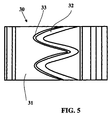
- FIG. 5 (representing a "flat" view of the radially outer surface of a rim 30 ) illustrates a particular case in which this rim has a bearing surface 31 provided with a surface clamping part 32 continues circumferentially and whose average profile on said bearing has a wavy geometric shape.
- a connection surface 33 making an angle different from 90 ° with the axial direction.
- Another embodiment consists in producing a plurality of ribs in relief on the bearing surface, the width of said ribs being substantially equal to the distance circumferential middle separating two consecutive ribs.
- These ribs can have a direction substantially coincident or inclined with the axial direction of the rim.
Landscapes
- Engineering & Computer Science (AREA)
- Mechanical Engineering (AREA)
- Tires In General (AREA)
- Rolling Contact Bearings (AREA)
- Testing Of Balance (AREA)
- Iron Core Of Rotating Electric Machines (AREA)
- Insulation, Fastening Of Motor, Generator Windings (AREA)
Abstract
Description
- soit continue dans la direction circonférentielle autour de la portée;
- soit composée de plusieurs éléments de relief, les distances circonférentielles entre chacun desdits éléments étant sensiblement égales; ces éléments de relief sont disposés selon une ligne circulaire concentrique à la portée d'appui.

- la figure 1 montre en coupe une jante monobloc selon l'invention pourvue d'une partie surfacique de serrage formée de quatre éléments en relief sur la portée d'appui régulièrement répartis dans la direction circonférentielle;
- la figure 2 montre une coupe partielle de la jante représentée à la figure 1, cette coupe étant prise dans un plan perpendiculaire à l'axe de rotation de la jante traversant par la partie surfacique de serrage;
- la figure 3 montre une coupe transversale d'une jante monobloc comportant une rainure de blocage latéral d'un anneau de soutien et pourvue d'une partie surfacique de serrage continue circonférentiellement;
- la figure 4 montre une variante d'exécution selon laquelle la portée d'appui d'une jante comporte deux parties surfaciques de serrage de développements et de largeurs axiales différents;
- la figure 5 montre la surface extérieure de la portée d'appui d'une jante selon l'invention comportant une partie surfacique de serrage continue circonférentiellement et ayant une géométrie moyenne ondulée.

Claims (11)
- Jante (1), destinée au montage d'un pneumatique comprenant au moins deux bourrelets, délimitée axialement par un premier bord et un deuxième bord de jante, comprenant, vue en section méridienne, au moins un premier siège de jante (2) et un deuxième siège de jante (3), au moins le premier siège de jante (2) a une génératrice dont l'extrémité axialement intérieure est sur un cercle de diamètre Φ1' supérieur au diamètre Φ1 du cercle sur lequel se trouve l'extrémité axialement extérieure,et au moins une portée d'appui (5) destinée à recevoir un appui de soutien annulaire par glissement dudit appui sur un côté de la jante, ladite portée (5) étant disposée entre les extrémités axialement intérieures des deux sièges et ayant une forme essentiellement cylindrique de développement minimal Dp au moins égal au développement de toute partie de jante comprise axialement entre ladite extrémité et le bord de jante correspondant au siège de jante le plus proche axialement de ladite extrémité, ladite jante étant caractérisée en ce que :la portée d'appui (5) comprend au moins une partie surfacique de serrage (9), chaque partie surfacique de serrage (9) étant régulièrement répartie dans la direction circonférentielle sur ladite portée et présentant un développement externe maximal Ds supérieur à Dp, ledit développement Ds étant mesuré sur une surface enveloppante concentrique à la portée (5), afin de créer au montage de l'anneau de soutien un serrage mécanique, entre ledit anneau et ladite partie surfacique de serrage, approprié pour assurer le maintien dudit anneau sur la portée.
- Jante selon la revendication 1 caractérisée en ce que chaque partie surfacique de serrage (9) a une largeur axiale Ls comprise entre 10% et 50% de la largeur axiale Lp de la portée d'appui.
- Jante selon la revendication 2 caractérisée en ce que chaque partie surfacique de serrage (9) se raccorde, avec la portée (5) du côté du siège de jante par lequel on enfile l'anneau de soutien, au moyen d'une surface (9') engendrée par une génératrice se raccordant en un premier point sur la partie surfacique de serrage (9) et en un second point de la portée (5), la droite passant par lesdits deux points faisant un angle différent de 90° avec l'axe de rotation de la jante dans le but de faciliter la mise en place de l'anneau de soutien.
- Jante selon l'une des revendications 1 à 3 caractérisée en ce que au moins une partie surfacique de serrage (9) est continue circonférentiellement et est inscrite à l'intérieur d'une surface enveloppante cylindrique de développement Ds, ladite surface enveloppante étant concentrique de la portée d'appui (5).
- Jante selon l'une des revendications 1 à 4 caractérisée en ce que la portée d'appui (24) comprend deux parties surfaciques de serrage (26, 28) distinctes l'une de l'autre axialement, lesdites parties étant de largeur axiale Ls' et Ls'' différentes, la partie de largeur axiale la plus petite étant située entre l'autre partie et le côté de la jante sur lequel on enfile l'appui.
- Jante selon l'une des revendications 1 à 5 caractérisée en ce qu'au moins une partie surfacique de serrage (9) est composée d'éléments de relief (91, 92, 93, 94) régulièrement répartis dans la direction circonférentielle sur la portée (5), chaque élément de relief ayant une largeur axiale Ls au moins égale à 10% de Lp, le développement Ds de la surface cylindrique enveloppant l'ensemble desdits éléments de relief d'une même partie surfacique de serrage étant strictement supérieur à Dp.
- Jante selon la revendication 6 caractérisée en ce qu'elle est pourvue d'au moins deux parties surfaciques de serrage séparées les unes des autres dans le sens axial, au moins une première partie surfacique de serrage et une deuxième partie surfacique de serrage étant composées d'un nombre égal d'éléments de relief régulièrement répartis dans la direction circonférentielle, les éléments de relief de ladite première partie étant décalés par rapport aux éléments de relief de ladite deuxième partie dans la direction circonférentielle.
- Jante selon l'une des revendications 1 à 6 caractérisée en ce qu'au moins une partie surfacique de serrage (32) présente, dans la direction axiale, une trace moyenne en zigzag ou ondulée.
- Jante selon la revendication 1 caractérisée en ce que la partie surfacique de serrage est tronconique et fait avec la direction axiale un angle moyen compris entre 1° et 5°, le développement minimal de ladite partie surfacique se trouvant du côté du siège de jante sur lequel on enfile l'appui.
- Jante selon l'une des revendications 1 à 9 caractérisée en ce que la portée d'appui (24) comporte en outre une butée (27) destinée à limiter axialement le mouvement de mise en place de l'anneau de soutien et en ce qu'une partie surfacique de serrage est disposée à proximité de ladite butée.
- Jante selon la revendication 10 caractérisée en ce que la partie surfacique de serrage (26) à proximité de la butée (27) est séparée de ladite butée par une rainure (29).
Applications Claiming Priority (2)
| Application Number | Priority Date | Filing Date | Title |
|---|---|---|---|
| FR9913964A FR2800671A1 (fr) | 1999-11-04 | 1999-11-04 | Jante destinee a recevoir un anneau de soutien |
| FR9913964 | 1999-11-04 |
Publications (2)
| Publication Number | Publication Date |
|---|---|
| EP1097823A1 true EP1097823A1 (fr) | 2001-05-09 |
| EP1097823B1 EP1097823B1 (fr) | 2005-01-19 |
Family
ID=9551825
Family Applications (1)
| Application Number | Title | Priority Date | Filing Date |
|---|---|---|---|
| EP00122630A Expired - Lifetime EP1097823B1 (fr) | 1999-11-04 | 2000-10-17 | Jante destinée à recevoir un anneau de soutien |
Country Status (15)
| Country | Link |
|---|---|
| US (1) | US6415839B1 (fr) |
| EP (1) | EP1097823B1 (fr) |
| JP (1) | JP2001354002A (fr) |
| KR (1) | KR20010051422A (fr) |
| CN (1) | CN1163365C (fr) |
| AT (1) | ATE287338T1 (fr) |
| AU (1) | AU769417B2 (fr) |
| BR (1) | BR0005207A (fr) |
| CA (1) | CA2324519A1 (fr) |
| DE (1) | DE60017525T2 (fr) |
| FR (1) | FR2800671A1 (fr) |
| HU (1) | HU222311B1 (fr) |
| MX (1) | MXPA00010693A (fr) |
| PL (1) | PL343664A1 (fr) |
| RU (1) | RU2261803C2 (fr) |
Cited By (2)
| Publication number | Priority date | Publication date | Assignee | Title |
|---|---|---|---|---|
| FR2872739A1 (fr) * | 2004-07-08 | 2006-01-13 | Michelin Soc Tech | Jante de vehicule destinee au montage d'un pneumatique et d'un appui de soutien |
| WO2006010681A1 (fr) * | 2004-07-08 | 2006-02-02 | Societe De Technologie Michelin | Jante de véhicule destinée au montage d'un pneumatique et d'un appui de soutien |
Families Citing this family (25)
| Publication number | Priority date | Publication date | Assignee | Title |
|---|---|---|---|---|
| US6598633B1 (en) * | 1999-11-04 | 2003-07-29 | Michelin Recherche Et Technique S.A. | Tire safety support and rim and support assembly containing centering means and with facilitated mounting |
| FR2805214B1 (fr) * | 2000-02-21 | 2002-04-05 | Michelin Soc Tech | Jante et ensemble d'une telle jante avec un appui de soutien |
| FR2805491B1 (fr) * | 2000-02-28 | 2002-05-10 | Michelin Soc Tech | Jante avec sieges inclines vers l'exterieur et ensembles comprenant une telle jante et un appui de soutien gonfle |
| US8266465B2 (en) | 2000-07-26 | 2012-09-11 | Bridgestone Americas Tire Operation, LLC | System for conserving battery life in a battery operated device |
| US7161476B2 (en) | 2000-07-26 | 2007-01-09 | Bridgestone Firestone North American Tire, Llc | Electronic tire management system |
| FR2818585A1 (fr) * | 2000-12-22 | 2002-06-28 | Michelin Soc Tech | Ensemble d'une jante et d'un appui de soutien |
| US7100654B2 (en) * | 2001-04-30 | 2006-09-05 | Pirelli Pneumatici S.P.A. | Safety support for a vehicle wheel and safety system and vehicle wheel including the safety support |
| FR2827548A1 (fr) * | 2001-07-17 | 2003-01-24 | Michelin Soc Tech | Ensemble monte tubeless pour cycle, jante et pneumatique tubeless |
| US6916073B2 (en) * | 2001-09-12 | 2005-07-12 | Michelin Recherche Et Technique | Pneumatic tire and wheel allowing unassisted manual mounting of the tire and a method for designing such a tire and wheel |
| FR2841825B1 (fr) * | 2002-07-08 | 2004-08-27 | Michelin Soc Tech | Jante de roue constituee de deux structures assemblees |
| JP4076451B2 (ja) * | 2003-01-28 | 2008-04-16 | トピー工業株式会社 | 不等厚リム用リム素材、不等厚リム、不等厚リムの製造方法 |
| WO2005005171A1 (fr) * | 2003-06-20 | 2005-01-20 | Societe De Technologie Michelin | Ensemble comprenant une jante et un support a affaissement limite |
| JP3808858B2 (ja) * | 2003-10-07 | 2006-08-16 | 住友ゴム工業株式会社 | サポートリング、及びタイヤ組立体 |
| DE60333045D1 (de) | 2003-12-19 | 2010-07-29 | Michelin Soc Tech | Run-flat-stützring mit verbesserten befestigungsmerkmalen |
| US7243694B2 (en) * | 2003-12-19 | 2007-07-17 | Michelin Recherche Et Technique S. A. | Run-flat support ring with improved mounting features |
| WO2005068224A1 (fr) * | 2003-12-19 | 2005-07-28 | Societe De Technologie Michelin | Jante amelioree pour ensembles pneumatiques avec possibilite de roulage a plat |
| JP4410575B2 (ja) * | 2004-02-02 | 2010-02-03 | 住友ゴム工業株式会社 | サポートリング及びそれを用いたタイヤ組立体 |
| US7104302B2 (en) * | 2004-06-08 | 2006-09-12 | Michelin Recherche Et Technique S.A. | Run-flat support ring with internal fin |
| US7096907B2 (en) * | 2004-06-08 | 2006-08-29 | Michelin Recherche Et Technique S.A. | Run-flat support ring with integrated shelf design and improved mounting features |
| US7047800B2 (en) * | 2004-06-10 | 2006-05-23 | Michelin Recherche Et Technique S.A. | Piezoelectric ceramic fibers having metallic cores |
| FR2889110B1 (fr) * | 2005-07-28 | 2009-10-09 | Michelin Soc Tech | Ensemble roue et pneumatique avec des sieges de diametres inegaux dont le pneumatique comporte des flancs de largeur superieure a la jante |
| FR2900095B1 (fr) * | 2006-04-21 | 2008-07-04 | Michelin Soc Tech | Jante de vehicule destinee au montage d'un pneumatique et d'un appui de soutien et procede de montage d'un ensemble pneumatique-roue pourvue d'une telle jante |
| US7730918B2 (en) * | 2006-04-21 | 2010-06-08 | Michelin Recherche Et Technique S.A. | Vehicle rim intended for mounting a tire and a bearing support and mounting process for a tire/wheel assembly provided with such a rim |
| FR2910378B1 (fr) * | 2006-12-22 | 2009-03-06 | Michelin Soc Tech | Jante de vehicule destinee au montage d'un pneumatique. |
| RU2749143C1 (ru) * | 2019-09-13 | 2021-06-07 | Игорь Венедиктович Балабин | Конструкция колеса с пневматической шиной для работы на мобильной машине с большим развалом |
Citations (4)
| Publication number | Priority date | Publication date | Assignee | Title |
|---|---|---|---|---|
| FR2699121A1 (fr) * | 1992-12-11 | 1994-06-17 | Michelin & Cie | Ensemble formé d'un pneumatique, d'une jante et d'un anneau de soutien. |
| FR2713557A1 (fr) * | 1993-12-08 | 1995-06-16 | Michelin & Cie | Jante, anneau de soutien et ensemble comprenant lesdits éléments. |
| FR2713558A1 (fr) * | 1993-12-08 | 1995-06-16 | Michelin & Cie | Pneumatique, jante, anneau de soutien et ensemble comprenant lesdits éléments. |
| FR2741567A1 (fr) * | 1995-11-27 | 1997-05-30 | Michelin & Cie | Roue avec appui de securite et capteur de pression incorpore |
Family Cites Families (2)
| Publication number | Priority date | Publication date | Assignee | Title |
|---|---|---|---|---|
| FR2746347A1 (fr) * | 1996-03-19 | 1997-09-26 | Michelin & Cie | Appui de securite en materiau elastomerique souple pour pneumatique |
| FR2748695B1 (fr) * | 1996-05-15 | 1998-06-26 | Michelin & Cie | Roue avec jante ayant des sieges inclines vers l'exterieur |
-
1999
- 1999-11-04 FR FR9913964A patent/FR2800671A1/fr not_active Withdrawn
-
2000
- 2000-10-17 AT AT00122630T patent/ATE287338T1/de not_active IP Right Cessation
- 2000-10-17 DE DE60017525T patent/DE60017525T2/de not_active Expired - Lifetime
- 2000-10-17 EP EP00122630A patent/EP1097823B1/fr not_active Expired - Lifetime
- 2000-10-26 HU HU0004166A patent/HU222311B1/hu not_active IP Right Cessation
- 2000-10-30 MX MXPA00010693A patent/MXPA00010693A/es active IP Right Grant
- 2000-10-31 BR BR0005207-8A patent/BR0005207A/pt active Search and Examination
- 2000-10-31 US US09/702,959 patent/US6415839B1/en not_active Expired - Fee Related
- 2000-10-31 CA CA002324519A patent/CA2324519A1/fr not_active Abandoned
- 2000-11-03 CN CNB001334115A patent/CN1163365C/zh not_active Expired - Fee Related
- 2000-11-03 PL PL00343664A patent/PL343664A1/xx unknown
- 2000-11-03 AU AU71401/00A patent/AU769417B2/en not_active Ceased
- 2000-11-03 KR KR1020000065124A patent/KR20010051422A/ko not_active Ceased
- 2000-11-03 RU RU2000127696/11A patent/RU2261803C2/ru not_active IP Right Cessation
- 2000-11-06 JP JP2000376668A patent/JP2001354002A/ja not_active Abandoned
Patent Citations (4)
| Publication number | Priority date | Publication date | Assignee | Title |
|---|---|---|---|---|
| FR2699121A1 (fr) * | 1992-12-11 | 1994-06-17 | Michelin & Cie | Ensemble formé d'un pneumatique, d'une jante et d'un anneau de soutien. |
| FR2713557A1 (fr) * | 1993-12-08 | 1995-06-16 | Michelin & Cie | Jante, anneau de soutien et ensemble comprenant lesdits éléments. |
| FR2713558A1 (fr) * | 1993-12-08 | 1995-06-16 | Michelin & Cie | Pneumatique, jante, anneau de soutien et ensemble comprenant lesdits éléments. |
| FR2741567A1 (fr) * | 1995-11-27 | 1997-05-30 | Michelin & Cie | Roue avec appui de securite et capteur de pression incorpore |
Cited By (2)
| Publication number | Priority date | Publication date | Assignee | Title |
|---|---|---|---|---|
| FR2872739A1 (fr) * | 2004-07-08 | 2006-01-13 | Michelin Soc Tech | Jante de vehicule destinee au montage d'un pneumatique et d'un appui de soutien |
| WO2006010681A1 (fr) * | 2004-07-08 | 2006-02-02 | Societe De Technologie Michelin | Jante de véhicule destinée au montage d'un pneumatique et d'un appui de soutien |
Also Published As
| Publication number | Publication date |
|---|---|
| CN1163365C (zh) | 2004-08-25 |
| EP1097823B1 (fr) | 2005-01-19 |
| DE60017525D1 (de) | 2005-02-24 |
| US6415839B1 (en) | 2002-07-09 |
| BR0005207A (pt) | 2001-06-19 |
| AU769417B2 (en) | 2004-01-29 |
| HU222311B1 (hu) | 2003-06-28 |
| FR2800671A1 (fr) | 2001-05-11 |
| CN1294985A (zh) | 2001-05-16 |
| MXPA00010693A (es) | 2002-07-22 |
| RU2261803C2 (ru) | 2005-10-10 |
| PL343664A1 (en) | 2001-05-07 |
| ATE287338T1 (de) | 2005-02-15 |
| KR20010051422A (ko) | 2001-06-25 |
| AU7140100A (en) | 2001-05-10 |
| DE60017525T2 (de) | 2006-03-23 |
| JP2001354002A (ja) | 2001-12-25 |
| CA2324519A1 (fr) | 2001-05-04 |
| HU0004166D0 (fr) | 2001-01-29 |
| HUP0004166A2 (hu) | 2001-10-28 |
Similar Documents
| Publication | Publication Date | Title |
|---|---|---|
| EP1097823B1 (fr) | Jante destinée à recevoir un anneau de soutien | |
| EP0796747B1 (fr) | Appui de sécurité en matériau élastomérique souple pour pneumatique | |
| EP0748287B1 (fr) | Pneumatique avec des bourrelets de structure amelioree et ensemble d'un tel pneumatique avec une jante adaptee | |
| EP1206357B1 (fr) | Ensemble d'une jante et d'un appui de soutien | |
| EP1355791A1 (fr) | Jante de roue en tole d'acier a profil optimise | |
| FR2818585A1 (fr) | Ensemble d'une jante et d'un appui de soutien | |
| CH636052A5 (en) | Wheel rim/tyre assembly | |
| EP0170085B1 (fr) | Jante de sécurité comportant un bossage de retenue axiale du bourrelet de grande hauteur, et ensemble pneumatique utilisant une telle jante | |
| EP1540229A1 (fr) | Collier de serrage | |
| EP1868823B1 (fr) | Anneau de verrouillage dans un ensemble de montage d'un pneumatique sur un moyeu de vehicule | |
| EP1233874B1 (fr) | Appui de securite et ensemble appui et jante pour pneumatique comportant des moyens de centrage et a montage facilite | |
| WO2018020152A1 (fr) | Extenseur et jante pour ensemble roulant, ensemble forme par l'extenseur et la jante, et ensemble roulant les comprenant | |
| EP1838540B1 (fr) | Pneumatique dont au moins un siege de bourrelet comporte une nervure | |
| EP1551648B1 (fr) | Jante de roue constituee de deux structures assemblees | |
| EP1831035B1 (fr) | Bourrelet de pneumatique facilitant le montage et methode de construction d'un tel bourrelet | |
| EP1901928B1 (fr) | Jante de vehicule avec des sieges de diametres inegaux | |
| EP1981722A1 (fr) | Pneumatique avec des sièges de diamètres inégaux et à déport axial inversé à l'état gonflé | |
| EP3727882A1 (fr) | Élément de bandage | |
| FR2605937A1 (fr) | Roue de vehicule equipee d'un pneumatique monte sur la face interieure radiale de la jante | |
| CH633221A5 (en) | Wheel rim and tyre assembly | |
| EP1910104A1 (fr) | Appui de soutien optimise | |
| FR2910378A1 (fr) | Jante de vehicule destinee au montage d'un pneumatique. | |
| FR2888162A3 (fr) | Jante de vehicule avec des sieges de diametres inegaux | |
| FR2881989A1 (fr) | Jante de vehicule destinee au montage d'un pneumatique et d'un appui de soutien | |
| BE827614A (fr) | Roue pneumatique perfectionnee pour vehicules |
Legal Events
| Date | Code | Title | Description |
|---|---|---|---|
| PUAI | Public reference made under article 153(3) epc to a published international application that has entered the european phase |
Free format text: ORIGINAL CODE: 0009012 |
|
| AK | Designated contracting states |
Kind code of ref document: A1 Designated state(s): AT BE CH CY DE DK ES FI FR GB GR IE IT LI LU MC NL PT SE |
|
| AX | Request for extension of the european patent |
Free format text: AL;LT;LV;MK;RO;SI |
|
| 17P | Request for examination filed |
Effective date: 20011109 |
|
| AKX | Designation fees paid |
Free format text: AT BE CH CY DE DK ES FI FR GB GR IE IT LI LU MC NL PT SE |
|
| GRAP | Despatch of communication of intention to grant a patent |
Free format text: ORIGINAL CODE: EPIDOSNIGR1 |
|
| GRAS | Grant fee paid |
Free format text: ORIGINAL CODE: EPIDOSNIGR3 |
|
| GRAA | (expected) grant |
Free format text: ORIGINAL CODE: 0009210 |
|
| AK | Designated contracting states |
Kind code of ref document: B1 Designated state(s): AT BE CH CY DE DK ES FI FR GB GR IE IT LI LU MC NL PT SE |
|
| PG25 | Lapsed in a contracting state [announced via postgrant information from national office to epo] |
Ref country code: IE Free format text: LAPSE BECAUSE OF FAILURE TO SUBMIT A TRANSLATION OF THE DESCRIPTION OR TO PAY THE FEE WITHIN THE PRESCRIBED TIME-LIMIT Effective date: 20050119 Ref country code: AT Free format text: LAPSE BECAUSE OF FAILURE TO SUBMIT A TRANSLATION OF THE DESCRIPTION OR TO PAY THE FEE WITHIN THE PRESCRIBED TIME-LIMIT Effective date: 20050119 Ref country code: FI Free format text: LAPSE BECAUSE OF FAILURE TO SUBMIT A TRANSLATION OF THE DESCRIPTION OR TO PAY THE FEE WITHIN THE PRESCRIBED TIME-LIMIT Effective date: 20050119 Ref country code: NL Free format text: LAPSE BECAUSE OF FAILURE TO SUBMIT A TRANSLATION OF THE DESCRIPTION OR TO PAY THE FEE WITHIN THE PRESCRIBED TIME-LIMIT Effective date: 20050119 |
|
| REG | Reference to a national code |
Ref country code: GB Ref legal event code: FG4D Free format text: NOT ENGLISH |
|
| REG | Reference to a national code |
Ref country code: CH Ref legal event code: EP |
|
| REG | Reference to a national code |
Ref country code: IE Ref legal event code: FG4D Free format text: FRENCH |
|
| REF | Corresponds to: |
Ref document number: 60017525 Country of ref document: DE Date of ref document: 20050224 Kind code of ref document: P |
|
| PG25 | Lapsed in a contracting state [announced via postgrant information from national office to epo] |
Ref country code: GR Free format text: LAPSE BECAUSE OF FAILURE TO SUBMIT A TRANSLATION OF THE DESCRIPTION OR TO PAY THE FEE WITHIN THE PRESCRIBED TIME-LIMIT Effective date: 20050419 Ref country code: SE Free format text: LAPSE BECAUSE OF FAILURE TO SUBMIT A TRANSLATION OF THE DESCRIPTION OR TO PAY THE FEE WITHIN THE PRESCRIBED TIME-LIMIT Effective date: 20050419 Ref country code: DK Free format text: LAPSE BECAUSE OF FAILURE TO SUBMIT A TRANSLATION OF THE DESCRIPTION OR TO PAY THE FEE WITHIN THE PRESCRIBED TIME-LIMIT Effective date: 20050419 |
|
| PG25 | Lapsed in a contracting state [announced via postgrant information from national office to epo] |
Ref country code: ES Free format text: LAPSE BECAUSE OF FAILURE TO SUBMIT A TRANSLATION OF THE DESCRIPTION OR TO PAY THE FEE WITHIN THE PRESCRIBED TIME-LIMIT Effective date: 20050430 |
|
| GBT | Gb: translation of ep patent filed (gb section 77(6)(a)/1977) |
Effective date: 20050427 |
|
| NLV1 | Nl: lapsed or annulled due to failure to fulfill the requirements of art. 29p and 29m of the patents act | ||
| REG | Reference to a national code |
Ref country code: IE Ref legal event code: FD4D |
|
| PG25 | Lapsed in a contracting state [announced via postgrant information from national office to epo] |
Ref country code: CY Free format text: LAPSE BECAUSE OF FAILURE TO SUBMIT A TRANSLATION OF THE DESCRIPTION OR TO PAY THE FEE WITHIN THE PRESCRIBED TIME-LIMIT Effective date: 20051017 |
|
| PG25 | Lapsed in a contracting state [announced via postgrant information from national office to epo] |
Ref country code: CH Free format text: LAPSE BECAUSE OF NON-PAYMENT OF DUE FEES Effective date: 20051031 Ref country code: BE Free format text: LAPSE BECAUSE OF NON-PAYMENT OF DUE FEES Effective date: 20051031 Ref country code: MC Free format text: LAPSE BECAUSE OF NON-PAYMENT OF DUE FEES Effective date: 20051031 Ref country code: LI Free format text: LAPSE BECAUSE OF NON-PAYMENT OF DUE FEES Effective date: 20051031 |
|
| PLBE | No opposition filed within time limit |
Free format text: ORIGINAL CODE: 0009261 |
|
| STAA | Information on the status of an ep patent application or granted ep patent |
Free format text: STATUS: NO OPPOSITION FILED WITHIN TIME LIMIT |
|
| 26N | No opposition filed |
Effective date: 20051020 |
|
| REG | Reference to a national code |
Ref country code: CH Ref legal event code: PL |
|
| PGFP | Annual fee paid to national office [announced via postgrant information from national office to epo] |
Ref country code: GB Payment date: 20061023 Year of fee payment: 7 |
|
| PGFP | Annual fee paid to national office [announced via postgrant information from national office to epo] |
Ref country code: LU Payment date: 20061024 Year of fee payment: 7 |
|
| BERE | Be: lapsed |
Owner name: MICHELIN RECHERCHE ET TECHNIQUE S.A. Effective date: 20051031 Owner name: SOC. DE TECHNOLOGIE MICHELIN Effective date: 20051031 |
|
| PG25 | Lapsed in a contracting state [announced via postgrant information from national office to epo] |
Ref country code: PT Free format text: LAPSE BECAUSE OF NON-PAYMENT OF DUE FEES Effective date: 20050619 |
|
| GBPC | Gb: european patent ceased through non-payment of renewal fee |
Effective date: 20071017 |
|
| PG25 | Lapsed in a contracting state [announced via postgrant information from national office to epo] |
Ref country code: GB Free format text: LAPSE BECAUSE OF NON-PAYMENT OF DUE FEES Effective date: 20071017 |
|
| PGFP | Annual fee paid to national office [announced via postgrant information from national office to epo] |
Ref country code: IT Payment date: 20081025 Year of fee payment: 9 |
|
| PG25 | Lapsed in a contracting state [announced via postgrant information from national office to epo] |
Ref country code: LU Free format text: LAPSE BECAUSE OF NON-PAYMENT OF DUE FEES Effective date: 20071017 |
|
| PGFP | Annual fee paid to national office [announced via postgrant information from national office to epo] |
Ref country code: FR Payment date: 20101104 Year of fee payment: 11 |
|
| PGFP | Annual fee paid to national office [announced via postgrant information from national office to epo] |
Ref country code: DE Payment date: 20101022 Year of fee payment: 11 |
|
| PG25 | Lapsed in a contracting state [announced via postgrant information from national office to epo] |
Ref country code: IT Free format text: LAPSE BECAUSE OF NON-PAYMENT OF DUE FEES Effective date: 20091017 |
|
| REG | Reference to a national code |
Ref country code: FR Ref legal event code: ST Effective date: 20120629 |
|
| PG25 | Lapsed in a contracting state [announced via postgrant information from national office to epo] |
Ref country code: DE Free format text: LAPSE BECAUSE OF NON-PAYMENT OF DUE FEES Effective date: 20120501 |
|
| REG | Reference to a national code |
Ref country code: DE Ref legal event code: R119 Ref document number: 60017525 Country of ref document: DE Effective date: 20120501 |
|
| PG25 | Lapsed in a contracting state [announced via postgrant information from national office to epo] |
Ref country code: FR Free format text: LAPSE BECAUSE OF NON-PAYMENT OF DUE FEES Effective date: 20111102 |