EP1097801A1 - Piezoelectric press drive with hydraulic transmission device - Google Patents

Piezoelectric press drive with hydraulic transmission device Download PDF

Info

Publication number
EP1097801A1
EP1097801A1 EP00123428A EP00123428A EP1097801A1 EP 1097801 A1 EP1097801 A1 EP 1097801A1 EP 00123428 A EP00123428 A EP 00123428A EP 00123428 A EP00123428 A EP 00123428A EP 1097801 A1 EP1097801 A1 EP 1097801A1
Authority
EP
European Patent Office
Prior art keywords
die
piezoactor
transmission device
press according
press
Prior art date
Legal status (The legal status is an assumption and is not a legal conclusion. Google has not performed a legal analysis and makes no representation as to the accuracy of the status listed.)
Withdrawn
Application number
EP00123428A
Other languages
German (de)
French (fr)
Inventor
Achim Hess
Martin Gollhofer
Current Assignee (The listed assignees may be inaccurate. Google has not performed a legal analysis and makes no representation or warranty as to the accuracy of the list.)
Zfs Zentrum Fertigungstechnik Stuttgart Stiftung Des Offentlichen Rechts
ITT Manufacturing Enterprises LLC
Original Assignee
Zfs Zentrum Fertigungstechnik Stuttgart Stiftung Des Offentlichen Rechts
ITT Manufacturing Enterprises LLC
Priority date (The priority date is an assumption and is not a legal conclusion. Google has not performed a legal analysis and makes no representation as to the accuracy of the date listed.)
Filing date
Publication date
Application filed by Zfs Zentrum Fertigungstechnik Stuttgart Stiftung Des Offentlichen Rechts, ITT Manufacturing Enterprises LLC filed Critical Zfs Zentrum Fertigungstechnik Stuttgart Stiftung Des Offentlichen Rechts
Publication of EP1097801A1 publication Critical patent/EP1097801A1/en
Withdrawn legal-status Critical Current

Links

Images

Classifications

    • BPERFORMING OPERATIONS; TRANSPORTING
    • B30PRESSES
    • B30BPRESSES IN GENERAL
    • B30B1/00Presses, using a press ram, characterised by the features of the drive therefor, pressure being transmitted directly, or through simple thrust or tension members only, to the press ram or platen
    • B30B1/007Presses, using a press ram, characterised by the features of the drive therefor, pressure being transmitted directly, or through simple thrust or tension members only, to the press ram or platen using a fluid connection between the drive means and the press ram
    • BPERFORMING OPERATIONS; TRANSPORTING
    • B30PRESSES
    • B30BPRESSES IN GENERAL
    • B30B1/00Presses, using a press ram, characterised by the features of the drive therefor, pressure being transmitted directly, or through simple thrust or tension members only, to the press ram or platen

Definitions

  • the invention relates to a press, more particularly for cutting and moulding miniature components, with a reciprocating die.
  • a press more particularly for cutting and moulding miniature components, with a reciprocating die in that the drive of the die is effected by at least one piezoactor and in that a more particularly hydraulic transmission device is arranged between the piezoactor and the die.
  • the piezoactor offers the advantage that it has practically no moving mass as compared with a mechanical drive. Consequently, it is possible to attain very high velocities and accelerations using the press according to the invention. Using conventional presses, it is possible to manufacture approximately 2000 parts per unit of time. Using the press according to the invention, markedly increased frequencies and therefore quantities can be realised.
  • the use of the piezoactor allows for the representation of any chosen force/displacement profile. In contrast, it is only possible to represent a sinusoidal force/displacement profile using conventional mechanical presses with crank drives.
  • the transmission device is used in order to allow for larger displacement distances of the die.
  • the transmission device is preferably a hydraulic transmission device, since mechanical transmissions usually have a clearance which is too great for precision processing in the micrometer range.
  • a particular embodiment of the invention is characterised in that the transmission device comprises a double-action transmission piston, which is arranged between the piezoactor and the die.
  • the transmission device comprises a double-action transmission piston, which is arranged between the piezoactor and the die.
  • both the forward and the backward movement (pressure and traction) of the piezoactor is transmitted to the transmission piston. This offers the advantage that no restoring device is required for the transmission piston.
  • a further particular embodiment of the invention is characterised in that the die is accommodated with clearance in a first coupling half, which is prestressed with a second coupling half.
  • the coupling serves to compensate any possible displacement which may occur during the assembly of the press according to the invention. This offers the advantage that larger tolerances can be allowed in the case of the tool, which has a favourable effect on manufacturing costs.
  • a further particular embodiment of the invention is characterised in that a plurality of piezoactors actuated in parallel, more particular in modular form, is coupled with the transmission device.
  • This offers the advantage that it is also possible to realise large displacement distances using the press according to the invention.
  • the modular construction of the press allows for rapid adaptation of the press to different product settings.
  • a further particular embodiment of the invention is characterised in that a force sensor is connected to the piezoactor, which force sensor is connected to a control, which is connected to the voltage supply of the piezoactor.
  • a force sensor is connected to the piezoactor, which force sensor is connected to a control, which is connected to the voltage supply of the piezoactor.
  • the force sensor it is possible to continuously measure the force required for the processing operation. If the force increases during operation, this may mean that the tool is worn and needs to be replaced.
  • the press according to the invention it is possible to monitor tool wear. In this manner, undesirable die breakage can be prevented.
  • it is possible using the press according to the invention to vary the die force in a controlled manner via the voltage supply of the piezoactor. It is therefore possible to intervene in a controlled manner in the pressing procedure. It is thereby possible, for example, to process different materials or material thicknesses using the same tool.
  • a further particular embodiment of the invention is characterised in that a motion pickup is connected to the die, which motion pickup is connected to a control, which is connected to the voltage supply of the piezoactor.
  • a motion pickup is connected to the die, which motion pickup is connected to a control, which is connected to the voltage supply of the piezoactor.
  • a further particular embodiment of the invention is characterised in that the control and the voltage supply of the piezoactor are connected to a function generator.
  • the function generator it is possible to influence the voltage supply of the piezoactor in a controlled manner. Consequently, it is possible to preset any chosen force/displacement profile.
  • the press shown in section in Figure 1 comprises a base plate 1. Fitted to the base plate 1 is a plurality of columns 2, 3. The columns 2, 3 are used for securing a displaceable tool receiving plate 4.
  • a pressure plate 5 Arranged on the tool receiving plate 4 is a pressure plate 5.
  • a tool unit 6 is disposed on the pressure plate 5.
  • the tool unit 6 is formed by a lower tool half 7 and an upper tool half 8.
  • a die 9 is axially displaceably guided in the upper tool half 8.
  • the end of the die 9 remote from the lower tool half 7 is accommodated with clearance in a lower coupling half 10.
  • the lower coupling half 10 cooperates with an upper coupling half 11, in order to couple the die 9 with a push rod 12.
  • the push rod 12 is displaceably guided in a base plate 13 and projects with its end remote from the die 9 into a hydraulic transmission device 14.
  • the base plate 13 belongs to the hydraulic transmission device 14 and is supported by the columns 2, 3.
  • the hydraulic transmission device 14 is used to transmit the movement of two piezoactors 18, 19 via two transmission pistons 20, 21 and a suitable hydraulic fluid to the push rod 12.
  • the transmission pistons 20, 21 are constructed in three parts in order to allow for the securing of sealing rings in their centre.
  • the pistons 20 and 21 are accommodated in cylinder chambers 26, 27 in a housing base element 22 so as to reciprocate and are coupled with the piezoactors 18, 19.
  • a hydraulic fluid duct 23 provides a connection between the end face of the pistons 20, 21 remote from the piezoactors and the push rod 12.
  • Constructed on the push rod 12 is a first collar 24, which is acted upon by the hydraulic pressure on the side remote from the tool.
  • a second collar 25 is constructed on the push rod 12. On the side remote from the first collar 24, the second collar 25 communicates via ducts 28, 29 with the end faces of the pistons 20, 21 facing the piezoactors. Hydraulic fluid is disposed in the cylinder chambers 26, 27.
  • the block diagram illustrated in Figure 2 shows how the press illustrated in Figure 1 is controlled during operation.
  • the displacement movement of the die 9 is recorded with the aid of a motion pickup.
  • the piezoactors 18, 19, which are also referred to as piezo operators are equipped with force sensors.
  • the motion pickup and the force sensors supply their measurement values to a control, which communicates with a function generator and the voltage supply of the piezo operators.

Abstract

The invention relates to a press, more particularly for cutting and moulding miniature components, with a reciprocating die (9).
In order to provide a small and compact press, which can be economically manufactured, the drive of the die (9) is effected by at least one piezoactor (18, 19).
In addition, a more particularly hydraulic transmission device (14) is arranged between the piezoactor (18, 19) and the die (9).

Description

The invention relates to a press, more particularly for cutting and moulding miniature components, with a reciprocating die.
On account of the large moving masses, conventional mechanical presses are unsuitable for the precision processing of small parts in the electronics field or are very expensive to manufacture.
It is the object of the invention to provide a small and compact press which can be economically manufactured. In particular, precision processing in the micrometer range is to be possible.
This object is attained in a press, more particularly for cutting and moulding miniature components, with a reciprocating die in that the drive of the die is effected by at least one piezoactor and in that a more particularly hydraulic transmission device is arranged between the piezoactor and the die. The piezoactor offers the advantage that it has practically no moving mass as compared with a mechanical drive. Consequently, it is possible to attain very high velocities and accelerations using the press according to the invention. Using conventional presses, it is possible to manufacture approximately 2000 parts per unit of time. Using the press according to the invention, markedly increased frequencies and therefore quantities can be realised. In addition, the use of the piezoactor allows for the representation of any chosen force/displacement profile. In contrast, it is only possible to represent a sinusoidal force/displacement profile using conventional mechanical presses with crank drives.
Whilst it is possible using the piezoactor to realise relatively large forces, it is only possible to realise relative small displacement distances. The transmission device is used in order to allow for larger displacement distances of the die. The transmission device is preferably a hydraulic transmission device, since mechanical transmissions usually have a clearance which is too great for precision processing in the micrometer range.
A particular embodiment of the invention is characterised in that the transmission device comprises a double-action transmission piston, which is arranged between the piezoactor and the die. In the double-action principle, both the forward and the backward movement (pressure and traction) of the piezoactor is transmitted to the transmission piston. This offers the advantage that no restoring device is required for the transmission piston.
A further particular embodiment of the invention is characterised in that the die is accommodated with clearance in a first coupling half, which is prestressed with a second coupling half. In this manner, a so-called floating die guidance is realised. The coupling serves to compensate any possible displacement which may occur during the assembly of the press according to the invention. This offers the advantage that larger tolerances can be allowed in the case of the tool, which has a favourable effect on manufacturing costs.
A further particular embodiment of the invention is characterised in that a plurality of piezoactors actuated in parallel, more particular in modular form, is coupled with the transmission device. This offers the advantage that it is also possible to realise large displacement distances using the press according to the invention. Furthermore, the modular construction of the press allows for rapid adaptation of the press to different product settings.
A further particular embodiment of the invention is characterised in that a force sensor is connected to the piezoactor, which force sensor is connected to a control, which is connected to the voltage supply of the piezoactor. Using the force sensor, it is possible to continuously measure the force required for the processing operation. If the force increases during operation, this may mean that the tool is worn and needs to be replaced. Using the press according to the invention, it is possible to monitor tool wear. In this manner, undesirable die breakage can be prevented. Furthermore, it is possible using the press according to the invention to vary the die force in a controlled manner via the voltage supply of the piezoactor. It is therefore possible to intervene in a controlled manner in the pressing procedure. It is thereby possible, for example, to process different materials or material thicknesses using the same tool.
A further particular embodiment of the invention is characterised in that a motion pickup is connected to the die, which motion pickup is connected to a control, which is connected to the voltage supply of the piezoactor. Using the motion pickup, it is possible on the one hand to monitor the movement of the transmission piston or the die. On the other hand, it is possible to intervene in a controlled manner in the pressing procedure via the control and the voltage supply of the piezoactor.
A further particular embodiment of the invention is characterised in that the control and the voltage supply of the piezoactor are connected to a function generator. As a result of the function generator, it is possible to influence the voltage supply of the piezoactor in a controlled manner. Consequently, it is possible to preset any chosen force/displacement profile.
Further advantages, features and details of the invention will be clear from the following description, in which an embodiment of the invention is described in detail with reference to the drawings. In this respect, the features mentioned in the claims and the description can be fundamental to the invention either individually or in any chosen combination. In the drawings:
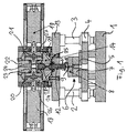
Figure 1
is a section through a press according to the invention; and
Figure 2
is a block diagram for the control of a press according to the invention.
The press shown in section in Figure 1 comprises a base plate 1. Fitted to the base plate 1 is a plurality of columns 2, 3. The columns 2, 3 are used for securing a displaceable tool receiving plate 4.
Arranged on the tool receiving plate 4 is a pressure plate 5. A tool unit 6 is disposed on the pressure plate 5. The tool unit 6 is formed by a lower tool half 7 and an upper tool half 8. A die 9 is axially displaceably guided in the upper tool half 8.
The end of the die 9 remote from the lower tool half 7 is accommodated with clearance in a lower coupling half 10. The lower coupling half 10 cooperates with an upper coupling half 11, in order to couple the die 9 with a push rod 12. The push rod 12 is displaceably guided in a base plate 13 and projects with its end remote from the die 9 into a hydraulic transmission device 14. The base plate 13 belongs to the hydraulic transmission device 14 and is supported by the columns 2, 3.
The hydraulic transmission device 14 is used to transmit the movement of two piezoactors 18, 19 via two transmission pistons 20, 21 and a suitable hydraulic fluid to the push rod 12. The transmission pistons 20, 21 are constructed in three parts in order to allow for the securing of sealing rings in their centre. The pistons 20 and 21 are accommodated in cylinder chambers 26, 27 in a housing base element 22 so as to reciprocate and are coupled with the piezoactors 18, 19. A hydraulic fluid duct 23 provides a connection between the end face of the pistons 20, 21 remote from the piezoactors and the push rod 12. Constructed on the push rod 12 is a first collar 24, which is acted upon by the hydraulic pressure on the side remote from the tool. In addition, a second collar 25 is constructed on the push rod 12. On the side remote from the first collar 24, the second collar 25 communicates via ducts 28, 29 with the end faces of the pistons 20, 21 facing the piezoactors. Hydraulic fluid is disposed in the cylinder chambers 26, 27.
In Figure 1, the piezoactors 18 and 19 are in their displaced state. The transmission pistons 20 and 21 have moved towards one another. Consequently, the push rod 12 and the die 9 have been moved towards the pressure plate 5.
When the piezoactors 18, 19 move away from one another, this also results in the transmission pistons 20, 21 moving away from one another. Consequently, the hydraulic fluid disposed on the side of the pistons 20, 21 remote from the piezoactors is displaced. This displacement is transmitted via the ducts 28, 29 to the second collar 25 of the push rod 12. In this manner, the push rod 12 is moved back into its starting position.
The block diagram illustrated in Figure 2 shows how the press illustrated in Figure 1 is controlled during operation. On the one hand, the displacement movement of the die 9 is recorded with the aid of a motion pickup. In addition, the piezoactors 18, 19, which are also referred to as piezo operators, are equipped with force sensors. The motion pickup and the force sensors supply their measurement values to a control, which communicates with a function generator and the voltage supply of the piezo operators.

Claims (7)

  1. A press, more particularly for cutting and moulding miniature components, with a reciprocating die (9), characterised in that the drive of the die (9) is effected by means of at least one piezoactor (18, 19), and a more particularly hydraulic transmission device (14) is arranged between the piezoactor (18, 19) and the die (9).
  2. A press according to claim 1, characterised in that the transmission device (14) comprises a double-action transmission piston (20, 21), which is arranged between the piezoactor (18, 19) and the die (9).
  3. A press according to one of the preceding claims, characterised in that the die (9) is accommodated with clearance in a first coupling half (10), which is prestressed with a second coupling half (11).
  4. A press according to one of the preceding claims, characterised in that a plurality of piezoactors (18, 19) actuated in parallel, more particular in modular form, is coupled with the transmission device (14).
  5. A press according to one of the preceding claims, characterised in that a force sensor is connected to the piezoactors (18, 19), which force sensor is connected to a control, which is connected to the voltage supply of the piezoactor (18, 19).
  6. A press according to one of the preceding claims, characterised in that a motion pickup is connected to the die (9), which motion pickup is connected to a control, which is connected to the voltage supply of the piezoactor (18, 19).
  7. A press according to claim 5 or 6, characterised in that the control and the voltage supply of the piezoactor (18, 19) are connected to a function generator.
EP00123428A 1999-11-04 2000-11-02 Piezoelectric press drive with hydraulic transmission device Withdrawn EP1097801A1 (en)

Applications Claiming Priority (2)

Application Number Priority Date Filing Date Title
DE19953244 1999-11-04
DE1999153244 DE19953244A1 (en) 1999-11-04 1999-11-04 Press

Publications (1)

Publication Number Publication Date
EP1097801A1 true EP1097801A1 (en) 2001-05-09

Family

ID=7928002

Family Applications (1)

Application Number Title Priority Date Filing Date
EP00123428A Withdrawn EP1097801A1 (en) 1999-11-04 2000-11-02 Piezoelectric press drive with hydraulic transmission device

Country Status (2)

Country Link
EP (1) EP1097801A1 (en)
DE (1) DE19953244A1 (en)

Cited By (2)

* Cited by examiner, † Cited by third party
Publication number Priority date Publication date Assignee Title
EP1602472A1 (en) 2004-06-02 2005-12-07 SMS Meer GmbH Process and apparatus for preparing a powder compact
DE102005027032A1 (en) * 2005-06-11 2006-12-28 Sms Meer Gmbh Device for producing a molded part

Families Citing this family (1)

* Cited by examiner, † Cited by third party
Publication number Priority date Publication date Assignee Title
DE102007050578B4 (en) * 2007-10-20 2016-02-18 Hofer Forschungs- Und Entwicklungs Gmbh Transmission actuator and gearbox

Citations (6)

* Cited by examiner, † Cited by third party
Publication number Priority date Publication date Assignee Title
JPS60177897A (en) * 1984-02-24 1985-09-11 日本電信電話株式会社 Piezoelectric type drill
JPS63286299A (en) * 1987-05-19 1988-11-22 Komatsu Ltd Controller for pressing machine
CH671187A5 (en) * 1986-12-23 1989-08-15 Autophon Ascom Ag Sheet stamping machine - with electromagnetic drive made of piezoelectric stack controlled by a pulsed voltage
US5095725A (en) * 1989-05-12 1992-03-17 Fuji Electric Co., Ltd. Press and actuator using piezoelectric element
US5138217A (en) * 1989-05-12 1992-08-11 Fuji Electric Co., Ltd. Driving power unit for piezoactuator system and method
JPH11179600A (en) * 1997-12-16 1999-07-06 Uht Corp Punch press

Family Cites Families (1)

* Cited by examiner, † Cited by third party
Publication number Priority date Publication date Assignee Title
DE19705893A1 (en) * 1997-02-15 1998-08-20 Wasmuth Thomas Dipl Ing Modular setting unit for fluid control

Patent Citations (6)

* Cited by examiner, † Cited by third party
Publication number Priority date Publication date Assignee Title
JPS60177897A (en) * 1984-02-24 1985-09-11 日本電信電話株式会社 Piezoelectric type drill
CH671187A5 (en) * 1986-12-23 1989-08-15 Autophon Ascom Ag Sheet stamping machine - with electromagnetic drive made of piezoelectric stack controlled by a pulsed voltage
JPS63286299A (en) * 1987-05-19 1988-11-22 Komatsu Ltd Controller for pressing machine
US5095725A (en) * 1989-05-12 1992-03-17 Fuji Electric Co., Ltd. Press and actuator using piezoelectric element
US5138217A (en) * 1989-05-12 1992-08-11 Fuji Electric Co., Ltd. Driving power unit for piezoactuator system and method
JPH11179600A (en) * 1997-12-16 1999-07-06 Uht Corp Punch press

Non-Patent Citations (2)

* Cited by examiner, † Cited by third party
Title
PATENT ABSTRACTS OF JAPAN vol. 013, no. 094 (M - 804) 6 March 1989 (1989-03-06) *
PATENT ABSTRACTS OF JAPAN vol. 1999, no. 12 29 October 1999 (1999-10-29) *

Cited By (4)

* Cited by examiner, † Cited by third party
Publication number Priority date Publication date Assignee Title
EP1602472A1 (en) 2004-06-02 2005-12-07 SMS Meer GmbH Process and apparatus for preparing a powder compact
US7150851B2 (en) 2004-06-02 2006-12-19 Sms Meer Gmbh Powder press
DE102005027032A1 (en) * 2005-06-11 2006-12-28 Sms Meer Gmbh Device for producing a molded part
DE102005027032B4 (en) * 2005-06-11 2007-06-28 Sms Meer Gmbh Device for producing a molded part

Also Published As

Publication number Publication date
DE19953244A1 (en) 2001-05-17

Similar Documents

Publication Publication Date Title
KR101531434B1 (en) Drive apparatus and method for a press machine
US7165437B2 (en) Mechanical press device
US6240818B1 (en) Precision blanking press with knife-edged ring and counter cylinder
GB1599207A (en) Cold forming process and apparatus
EP0873855A3 (en) Method and apparatus for manufacturing moulded articles in hard metal, ceramic, sintered metal or similar
JP3949057B2 (en) Hydraulic mechanical closure device
EP0298456A2 (en) Full enclosed die forging apparatus
CN104972684A (en) Pressing device for processing a workpiece
EP1097801A1 (en) Piezoelectric press drive with hydraulic transmission device
US5478225A (en) Tool set type powder compacting press
CN1507377A (en) Method employing high kinetic energy for working of material
EP1097800A1 (en) Piezoelectric press drive
ATE68409T1 (en) PRESS FOR THE MANUFACTURE OF MOLDINGS FROM POWDER OR GRANULATE MATERIALS.
EP0263721B1 (en) Hydraulic overload protector for mechanical press
JP3917480B2 (en) Mold clamping device and method of operating the same
US6539853B1 (en) Smart card connector with retain and eject means
KR20150114659A (en) Lower knock out device of double drive type
CA1051229A (en) Cam actuated ejector mechanisms for presses
SU1478544A1 (en) Apparatus for working parts with abrasive mass suppled under pressure
SU1574328A1 (en) Arrangement for forming parts from continuous material
CN111770831B (en) Powder press with toggle lever drive and electric drive
JPH05104288A (en) Cylinder system actuator
SU967650A1 (en) Pneumatic control system for internal hammer-vibropress
RU2237808C2 (en) Power hammer for destroying oversizes of rock solids
SU1613218A1 (en) Arrangement for stamping

Legal Events

Date Code Title Description
PUAI Public reference made under article 153(3) epc to a published international application that has entered the european phase

Free format text: ORIGINAL CODE: 0009012

AK Designated contracting states

Kind code of ref document: A1

Designated state(s): AT BE CH CY DE DK ES FI FR GB GR IE IT LI LU MC NL PT SE TR

AX Request for extension of the european patent

Free format text: AL;LT;LV;MK;RO;SI

17P Request for examination filed

Effective date: 20010615

AKX Designation fees paid

Free format text: AT BE CH CY DE DK ES FI FR GB GR IE IT LI LU MC NL PT SE TR

17Q First examination report despatched

Effective date: 20040820

GRAP Despatch of communication of intention to grant a patent

Free format text: ORIGINAL CODE: EPIDOSNIGR1

STAA Information on the status of an ep patent application or granted ep patent

Free format text: STATUS: THE APPLICATION IS DEEMED TO BE WITHDRAWN

18D Application deemed to be withdrawn

Effective date: 20060131