EP1097796B1 - Process for wrapping a sheath with a foam layer, and tubular complex with wrapped sheath - Google Patents
Process for wrapping a sheath with a foam layer, and tubular complex with wrapped sheath Download PDFInfo
- Publication number
- EP1097796B1 EP1097796B1 EP00403040A EP00403040A EP1097796B1 EP 1097796 B1 EP1097796 B1 EP 1097796B1 EP 00403040 A EP00403040 A EP 00403040A EP 00403040 A EP00403040 A EP 00403040A EP 1097796 B1 EP1097796 B1 EP 1097796B1
- Authority
- EP
- European Patent Office
- Prior art keywords
- sheath
- foam
- strip
- tube
- process according
- Prior art date
- Legal status (The legal status is an assumption and is not a legal conclusion. Google has not performed a legal analysis and makes no representation as to the accuracy of the status listed.)
- Expired - Lifetime
Links
- 239000006260 foam Substances 0.000 title claims abstract description 71
- 238000000034 method Methods 0.000 title claims description 31
- 238000003466 welding Methods 0.000 claims abstract description 19
- 239000002984 plastic foam Substances 0.000 claims description 11
- 239000004698 Polyethylene Substances 0.000 claims description 10
- 229920003020 cross-linked polyethylene Polymers 0.000 claims description 9
- 239000004703 cross-linked polyethylene Substances 0.000 claims description 9
- 229920003023 plastic Polymers 0.000 claims description 8
- 239000004033 plastic Substances 0.000 claims description 8
- -1 polyethylene Polymers 0.000 claims description 8
- 229920000573 polyethylene Polymers 0.000 claims description 8
- 238000004026 adhesive bonding Methods 0.000 claims description 6
- 239000003570 air Substances 0.000 claims description 5
- 238000004132 cross linking Methods 0.000 claims description 5
- 229920001903 high density polyethylene Polymers 0.000 claims description 5
- 239000004700 high-density polyethylene Substances 0.000 claims description 5
- 238000007664 blowing Methods 0.000 claims description 4
- 238000001125 extrusion Methods 0.000 claims description 4
- 229910000831 Steel Inorganic materials 0.000 claims description 3
- 239000012080 ambient air Substances 0.000 claims description 3
- 239000004568 cement Substances 0.000 claims description 3
- 230000007062 hydrolysis Effects 0.000 claims description 3
- 238000006460 hydrolysis reaction Methods 0.000 claims description 3
- 239000004615 ingredient Substances 0.000 claims description 3
- 239000010959 steel Substances 0.000 claims description 3
- 229920005830 Polyurethane Foam Polymers 0.000 claims 1
- 239000011496 polyurethane foam Substances 0.000 claims 1
- 239000002002 slurry Substances 0.000 claims 1
- RYGMFSIKBFXOCR-UHFFFAOYSA-N Copper Chemical compound [Cu] RYGMFSIKBFXOCR-UHFFFAOYSA-N 0.000 description 7
- 229910052802 copper Inorganic materials 0.000 description 7
- 239000010949 copper Substances 0.000 description 7
- 239000004743 Polypropylene Substances 0.000 description 5
- 238000010438 heat treatment Methods 0.000 description 5
- 229920001155 polypropylene Polymers 0.000 description 5
- XLYOFNOQVPJJNP-UHFFFAOYSA-N water Substances O XLYOFNOQVPJJNP-UHFFFAOYSA-N 0.000 description 5
- 239000011248 coating agent Substances 0.000 description 4
- 238000000576 coating method Methods 0.000 description 4
- 239000000463 material Substances 0.000 description 4
- 210000004027 cell Anatomy 0.000 description 3
- 239000013529 heat transfer fluid Substances 0.000 description 3
- 238000009434 installation Methods 0.000 description 3
- 229920002635 polyurethane Polymers 0.000 description 3
- 239000004814 polyurethane Substances 0.000 description 3
- 238000010586 diagram Methods 0.000 description 2
- 238000009826 distribution Methods 0.000 description 2
- 230000000694 effects Effects 0.000 description 2
- 239000003292 glue Substances 0.000 description 2
- 238000009413 insulation Methods 0.000 description 2
- 239000002184 metal Substances 0.000 description 2
- 229910052751 metal Inorganic materials 0.000 description 2
- 239000002893 slag Substances 0.000 description 2
- 229920001169 thermoplastic Polymers 0.000 description 2
- 239000004416 thermosoftening plastic Substances 0.000 description 2
- 238000004804 winding Methods 0.000 description 2
- 239000004821 Contact adhesive Substances 0.000 description 1
- 230000001154 acute effect Effects 0.000 description 1
- 239000011083 cement mortar Substances 0.000 description 1
- 230000006835 compression Effects 0.000 description 1
- 238000007906 compression Methods 0.000 description 1
- 238000001816 cooling Methods 0.000 description 1
- 230000008030 elimination Effects 0.000 description 1
- 238000003379 elimination reaction Methods 0.000 description 1
- 210000000497 foam cell Anatomy 0.000 description 1
- 239000006261 foam material Substances 0.000 description 1
- 230000004927 fusion Effects 0.000 description 1
- 239000004519 grease Substances 0.000 description 1
- 239000011810 insulating material Substances 0.000 description 1
- 239000012948 isocyanate Substances 0.000 description 1
- 150000002513 isocyanates Chemical class 0.000 description 1
- 238000004519 manufacturing process Methods 0.000 description 1
- 238000003303 reheating Methods 0.000 description 1
- 238000007493 shaping process Methods 0.000 description 1
- 229920002545 silicone oil Polymers 0.000 description 1
- 229910000679 solder Inorganic materials 0.000 description 1
- 239000012815 thermoplastic material Substances 0.000 description 1
- 229920005992 thermoplastic resin Polymers 0.000 description 1
- 238000011282 treatment Methods 0.000 description 1
- 125000000391 vinyl group Chemical group [H]C([*])=C([H])[H] 0.000 description 1
- 229920002554 vinyl polymer Polymers 0.000 description 1
Images

Classifications
-
- F—MECHANICAL ENGINEERING; LIGHTING; HEATING; WEAPONS; BLASTING
- F16—ENGINEERING ELEMENTS AND UNITS; GENERAL MEASURES FOR PRODUCING AND MAINTAINING EFFECTIVE FUNCTIONING OF MACHINES OR INSTALLATIONS; THERMAL INSULATION IN GENERAL
- F16L—PIPES; JOINTS OR FITTINGS FOR PIPES; SUPPORTS FOR PIPES, CABLES OR PROTECTIVE TUBING; MEANS FOR THERMAL INSULATION IN GENERAL
- F16L59/00—Thermal insulation in general
- F16L59/14—Arrangements for the insulation of pipes or pipe systems
- F16L59/153—Arrangements for the insulation of pipes or pipe systems for flexible pipes
-
- B—PERFORMING OPERATIONS; TRANSPORTING
- B29—WORKING OF PLASTICS; WORKING OF SUBSTANCES IN A PLASTIC STATE IN GENERAL
- B29C—SHAPING OR JOINING OF PLASTICS; SHAPING OF MATERIAL IN A PLASTIC STATE, NOT OTHERWISE PROVIDED FOR; AFTER-TREATMENT OF THE SHAPED PRODUCTS, e.g. REPAIRING
- B29C53/00—Shaping by bending, folding, twisting, straightening or flattening; Apparatus therefor
- B29C53/36—Bending and joining, e.g. for making hollow articles
- B29C53/38—Bending and joining, e.g. for making hollow articles by bending sheets or strips at right angles to the longitudinal axis of the article being formed and joining the edges
- B29C53/48—Bending and joining, e.g. for making hollow articles by bending sheets or strips at right angles to the longitudinal axis of the article being formed and joining the edges for articles of indefinite length, i.e. bending a strip progressively
-
- B—PERFORMING OPERATIONS; TRANSPORTING
- B29—WORKING OF PLASTICS; WORKING OF SUBSTANCES IN A PLASTIC STATE IN GENERAL
- B29C—SHAPING OR JOINING OF PLASTICS; SHAPING OF MATERIAL IN A PLASTIC STATE, NOT OTHERWISE PROVIDED FOR; AFTER-TREATMENT OF THE SHAPED PRODUCTS, e.g. REPAIRING
- B29C63/00—Lining or sheathing, i.e. applying preformed layers or sheathings of plastics; Apparatus therefor
- B29C63/02—Lining or sheathing, i.e. applying preformed layers or sheathings of plastics; Apparatus therefor using sheet or web-like material
- B29C63/04—Lining or sheathing, i.e. applying preformed layers or sheathings of plastics; Apparatus therefor using sheet or web-like material by folding, winding, bending or the like
- B29C63/06—Lining or sheathing, i.e. applying preformed layers or sheathings of plastics; Apparatus therefor using sheet or web-like material by folding, winding, bending or the like around tubular articles
- B29C63/065—Lining or sheathing, i.e. applying preformed layers or sheathings of plastics; Apparatus therefor using sheet or web-like material by folding, winding, bending or the like around tubular articles continuously
-
- B—PERFORMING OPERATIONS; TRANSPORTING
- B29—WORKING OF PLASTICS; WORKING OF SUBSTANCES IN A PLASTIC STATE IN GENERAL
- B29C—SHAPING OR JOINING OF PLASTICS; SHAPING OF MATERIAL IN A PLASTIC STATE, NOT OTHERWISE PROVIDED FOR; AFTER-TREATMENT OF THE SHAPED PRODUCTS, e.g. REPAIRING
- B29C65/00—Joining or sealing of preformed parts, e.g. welding of plastics materials; Apparatus therefor
- B29C65/02—Joining or sealing of preformed parts, e.g. welding of plastics materials; Apparatus therefor by heating, with or without pressure
- B29C65/10—Joining or sealing of preformed parts, e.g. welding of plastics materials; Apparatus therefor by heating, with or without pressure using hot gases (e.g. combustion gases) or flames coming in contact with at least one of the parts to be joined
-
- B—PERFORMING OPERATIONS; TRANSPORTING
- B29—WORKING OF PLASTICS; WORKING OF SUBSTANCES IN A PLASTIC STATE IN GENERAL
- B29C—SHAPING OR JOINING OF PLASTICS; SHAPING OF MATERIAL IN A PLASTIC STATE, NOT OTHERWISE PROVIDED FOR; AFTER-TREATMENT OF THE SHAPED PRODUCTS, e.g. REPAIRING
- B29C66/00—General aspects of processes or apparatus for joining preformed parts
- B29C66/01—General aspects dealing with the joint area or with the area to be joined
- B29C66/05—Particular design of joint configurations
- B29C66/10—Particular design of joint configurations particular design of the joint cross-sections
- B29C66/11—Joint cross-sections comprising a single joint-segment, i.e. one of the parts to be joined comprising a single joint-segment in the joint cross-section
- B29C66/114—Single butt joints
- B29C66/1142—Single butt to butt joints
-
- B—PERFORMING OPERATIONS; TRANSPORTING
- B29—WORKING OF PLASTICS; WORKING OF SUBSTANCES IN A PLASTIC STATE IN GENERAL
- B29C—SHAPING OR JOINING OF PLASTICS; SHAPING OF MATERIAL IN A PLASTIC STATE, NOT OTHERWISE PROVIDED FOR; AFTER-TREATMENT OF THE SHAPED PRODUCTS, e.g. REPAIRING
- B29C66/00—General aspects of processes or apparatus for joining preformed parts
- B29C66/40—General aspects of joining substantially flat articles, e.g. plates, sheets or web-like materials; Making flat seams in tubular or hollow articles; Joining single elements to substantially flat surfaces
- B29C66/41—Joining substantially flat articles ; Making flat seams in tubular or hollow articles
- B29C66/43—Joining a relatively small portion of the surface of said articles
- B29C66/432—Joining a relatively small portion of the surface of said articles for making tubular articles or closed loops, e.g. by joining several sheets ; for making hollow articles or hollow preforms
- B29C66/4322—Joining a relatively small portion of the surface of said articles for making tubular articles or closed loops, e.g. by joining several sheets ; for making hollow articles or hollow preforms by joining a single sheet to itself
-
- B—PERFORMING OPERATIONS; TRANSPORTING
- B29—WORKING OF PLASTICS; WORKING OF SUBSTANCES IN A PLASTIC STATE IN GENERAL
- B29C—SHAPING OR JOINING OF PLASTICS; SHAPING OF MATERIAL IN A PLASTIC STATE, NOT OTHERWISE PROVIDED FOR; AFTER-TREATMENT OF THE SHAPED PRODUCTS, e.g. REPAIRING
- B29C66/00—General aspects of processes or apparatus for joining preformed parts
- B29C66/40—General aspects of joining substantially flat articles, e.g. plates, sheets or web-like materials; Making flat seams in tubular or hollow articles; Joining single elements to substantially flat surfaces
- B29C66/49—Internally supporting the, e.g. tubular, article during joining
-
- B—PERFORMING OPERATIONS; TRANSPORTING
- B29—WORKING OF PLASTICS; WORKING OF SUBSTANCES IN A PLASTIC STATE IN GENERAL
- B29C—SHAPING OR JOINING OF PLASTICS; SHAPING OF MATERIAL IN A PLASTIC STATE, NOT OTHERWISE PROVIDED FOR; AFTER-TREATMENT OF THE SHAPED PRODUCTS, e.g. REPAIRING
- B29C66/00—General aspects of processes or apparatus for joining preformed parts
- B29C66/80—General aspects of machine operations or constructions and parts thereof
- B29C66/83—General aspects of machine operations or constructions and parts thereof characterised by the movement of the joining or pressing tools
- B29C66/834—General aspects of machine operations or constructions and parts thereof characterised by the movement of the joining or pressing tools moving with the parts to be joined
- B29C66/8341—Roller, cylinder or drum types; Band or belt types; Ball types
- B29C66/83411—Roller, cylinder or drum types
- B29C66/83413—Roller, cylinder or drum types cooperating rollers, cylinders or drums
-
- B—PERFORMING OPERATIONS; TRANSPORTING
- B29—WORKING OF PLASTICS; WORKING OF SUBSTANCES IN A PLASTIC STATE IN GENERAL
- B29C—SHAPING OR JOINING OF PLASTICS; SHAPING OF MATERIAL IN A PLASTIC STATE, NOT OTHERWISE PROVIDED FOR; AFTER-TREATMENT OF THE SHAPED PRODUCTS, e.g. REPAIRING
- B29C65/00—Joining or sealing of preformed parts, e.g. welding of plastics materials; Apparatus therefor
- B29C65/02—Joining or sealing of preformed parts, e.g. welding of plastics materials; Apparatus therefor by heating, with or without pressure
- B29C65/10—Joining or sealing of preformed parts, e.g. welding of plastics materials; Apparatus therefor by heating, with or without pressure using hot gases (e.g. combustion gases) or flames coming in contact with at least one of the parts to be joined
- B29C65/103—Joining or sealing of preformed parts, e.g. welding of plastics materials; Apparatus therefor by heating, with or without pressure using hot gases (e.g. combustion gases) or flames coming in contact with at least one of the parts to be joined direct heating both surfaces to be joined
-
- B—PERFORMING OPERATIONS; TRANSPORTING
- B29—WORKING OF PLASTICS; WORKING OF SUBSTANCES IN A PLASTIC STATE IN GENERAL
- B29C—SHAPING OR JOINING OF PLASTICS; SHAPING OF MATERIAL IN A PLASTIC STATE, NOT OTHERWISE PROVIDED FOR; AFTER-TREATMENT OF THE SHAPED PRODUCTS, e.g. REPAIRING
- B29C65/00—Joining or sealing of preformed parts, e.g. welding of plastics materials; Apparatus therefor
- B29C65/02—Joining or sealing of preformed parts, e.g. welding of plastics materials; Apparatus therefor by heating, with or without pressure
- B29C65/18—Joining or sealing of preformed parts, e.g. welding of plastics materials; Apparatus therefor by heating, with or without pressure using heated tools
- B29C65/20—Joining or sealing of preformed parts, e.g. welding of plastics materials; Apparatus therefor by heating, with or without pressure using heated tools with direct contact, e.g. using "mirror"
-
- B—PERFORMING OPERATIONS; TRANSPORTING
- B29—WORKING OF PLASTICS; WORKING OF SUBSTANCES IN A PLASTIC STATE IN GENERAL
- B29C—SHAPING OR JOINING OF PLASTICS; SHAPING OF MATERIAL IN A PLASTIC STATE, NOT OTHERWISE PROVIDED FOR; AFTER-TREATMENT OF THE SHAPED PRODUCTS, e.g. REPAIRING
- B29C65/00—Joining or sealing of preformed parts, e.g. welding of plastics materials; Apparatus therefor
- B29C65/02—Joining or sealing of preformed parts, e.g. welding of plastics materials; Apparatus therefor by heating, with or without pressure
- B29C65/18—Joining or sealing of preformed parts, e.g. welding of plastics materials; Apparatus therefor by heating, with or without pressure using heated tools
- B29C65/24—Joining or sealing of preformed parts, e.g. welding of plastics materials; Apparatus therefor by heating, with or without pressure using heated tools characterised by the means for heating the tool
- B29C65/30—Electrical means
-
- B—PERFORMING OPERATIONS; TRANSPORTING
- B29—WORKING OF PLASTICS; WORKING OF SUBSTANCES IN A PLASTIC STATE IN GENERAL
- B29C—SHAPING OR JOINING OF PLASTICS; SHAPING OF MATERIAL IN A PLASTIC STATE, NOT OTHERWISE PROVIDED FOR; AFTER-TREATMENT OF THE SHAPED PRODUCTS, e.g. REPAIRING
- B29C66/00—General aspects of processes or apparatus for joining preformed parts
- B29C66/70—General aspects of processes or apparatus for joining preformed parts characterised by the composition, physical properties or the structure of the material of the parts to be joined; Joining with non-plastics material
- B29C66/71—General aspects of processes or apparatus for joining preformed parts characterised by the composition, physical properties or the structure of the material of the parts to be joined; Joining with non-plastics material characterised by the composition of the plastics material of the parts to be joined
-
- B—PERFORMING OPERATIONS; TRANSPORTING
- B29—WORKING OF PLASTICS; WORKING OF SUBSTANCES IN A PLASTIC STATE IN GENERAL
- B29C—SHAPING OR JOINING OF PLASTICS; SHAPING OF MATERIAL IN A PLASTIC STATE, NOT OTHERWISE PROVIDED FOR; AFTER-TREATMENT OF THE SHAPED PRODUCTS, e.g. REPAIRING
- B29C66/00—General aspects of processes or apparatus for joining preformed parts
- B29C66/70—General aspects of processes or apparatus for joining preformed parts characterised by the composition, physical properties or the structure of the material of the parts to be joined; Joining with non-plastics material
- B29C66/72—General aspects of processes or apparatus for joining preformed parts characterised by the composition, physical properties or the structure of the material of the parts to be joined; Joining with non-plastics material characterised by the structure of the material of the parts to be joined
- B29C66/727—General aspects of processes or apparatus for joining preformed parts characterised by the composition, physical properties or the structure of the material of the parts to be joined; Joining with non-plastics material characterised by the structure of the material of the parts to be joined being porous, e.g. foam
-
- B—PERFORMING OPERATIONS; TRANSPORTING
- B29—WORKING OF PLASTICS; WORKING OF SUBSTANCES IN A PLASTIC STATE IN GENERAL
- B29C—SHAPING OR JOINING OF PLASTICS; SHAPING OF MATERIAL IN A PLASTIC STATE, NOT OTHERWISE PROVIDED FOR; AFTER-TREATMENT OF THE SHAPED PRODUCTS, e.g. REPAIRING
- B29C66/00—General aspects of processes or apparatus for joining preformed parts
- B29C66/70—General aspects of processes or apparatus for joining preformed parts characterised by the composition, physical properties or the structure of the material of the parts to be joined; Joining with non-plastics material
- B29C66/73—General aspects of processes or apparatus for joining preformed parts characterised by the composition, physical properties or the structure of the material of the parts to be joined; Joining with non-plastics material characterised by the intensive physical properties of the material of the parts to be joined, by the optical properties of the material of the parts to be joined, by the extensive physical properties of the parts to be joined, by the state of the material of the parts to be joined or by the material of the parts to be joined being a thermoplastic or a thermoset
- B29C66/737—General aspects of processes or apparatus for joining preformed parts characterised by the composition, physical properties or the structure of the material of the parts to be joined; Joining with non-plastics material characterised by the intensive physical properties of the material of the parts to be joined, by the optical properties of the material of the parts to be joined, by the extensive physical properties of the parts to be joined, by the state of the material of the parts to be joined or by the material of the parts to be joined being a thermoplastic or a thermoset characterised by the state of the material of the parts to be joined
- B29C66/7371—General aspects of processes or apparatus for joining preformed parts characterised by the composition, physical properties or the structure of the material of the parts to be joined; Joining with non-plastics material characterised by the intensive physical properties of the material of the parts to be joined, by the optical properties of the material of the parts to be joined, by the extensive physical properties of the parts to be joined, by the state of the material of the parts to be joined or by the material of the parts to be joined being a thermoplastic or a thermoset characterised by the state of the material of the parts to be joined oriented or heat-shrinkable
- B29C66/73715—General aspects of processes or apparatus for joining preformed parts characterised by the composition, physical properties or the structure of the material of the parts to be joined; Joining with non-plastics material characterised by the intensive physical properties of the material of the parts to be joined, by the optical properties of the material of the parts to be joined, by the extensive physical properties of the parts to be joined, by the state of the material of the parts to be joined or by the material of the parts to be joined being a thermoplastic or a thermoset characterised by the state of the material of the parts to be joined oriented or heat-shrinkable heat-shrinkable
-
- B—PERFORMING OPERATIONS; TRANSPORTING
- B29—WORKING OF PLASTICS; WORKING OF SUBSTANCES IN A PLASTIC STATE IN GENERAL
- B29K—INDEXING SCHEME ASSOCIATED WITH SUBCLASSES B29B, B29C OR B29D, RELATING TO MOULDING MATERIALS OR TO MATERIALS FOR MOULDS, REINFORCEMENTS, FILLERS OR PREFORMED PARTS, e.g. INSERTS
- B29K2105/00—Condition, form or state of moulded material or of the material to be shaped
- B29K2105/04—Condition, form or state of moulded material or of the material to be shaped cellular or porous
-
- B—PERFORMING OPERATIONS; TRANSPORTING
- B29—WORKING OF PLASTICS; WORKING OF SUBSTANCES IN A PLASTIC STATE IN GENERAL
- B29L—INDEXING SCHEME ASSOCIATED WITH SUBCLASS B29C, RELATING TO PARTICULAR ARTICLES
- B29L2023/00—Tubular articles
- B29L2023/22—Tubes or pipes, i.e. rigid
- B29L2023/225—Insulated
Definitions
- the invention relates to a method for surround a plastic sheath that may contain a tube which can be drawn in this sheath, by a layer of foam plastic material, in particular thermally insulating.
- the square head process is also greedy in energy because the tube to be covered scrolls in the square and removes calories.
- JP 59 230721 relates to a method for surrounding a tube by a strip of plastic foam; a outer layer is extruded around the entire tube and its foam envelope. It will therefore be difficult to push back or cut the foam envelope since you will first have to clear the outer layer. In furthermore, no sliding of the foam layer relatively to the tube does not appear possible.
- DE 1915768 A relates to a method and a device to make tabular objects from foam of thermoplastic resin.
- a strip of foam we wrap it around a longitudinal axis, with heating the edges to weld them.
- a cylindrical core is provided for the winding phase. Yes the core is flexible, it can be extracted from the tube by a slit. It is also possible to keep the nucleus consisting for example of a copper tube.
- a layer of thermally insulating material may also be provided. No indication is provided to avoid adhesion of the foam wrap to the inner tube.
- the object of the invention is to provide a process for surrounding a sheath by a layer of plastic foam which allows avoid too high adhesion of the layer to item. It is desirable that the process also allows avoid high temperatures when applying the foam so that it can be used around sheaths in thermoplastic material, in particular of a sheath which can contain a tube which can be pulled into the sheath.
- the process should also be economical and simple and reliable to use.
- the sheath is corrugated.
- the foam envelope is made waterproof cement slag.
- the sheath may be made of polychloride of vinyl (PVC), or polypropylene (PP) or polyethylene (PE).
- Tape can be prepared by foam extrusion near the sheath to be surrounded.
- the sheath to be surrounded and the band are advantageously drawn in abutment against one another, in particular from reels that are unwound, and the tape is applied around the sheath crossing a funnel-shaped device having a slit longitudinal in an area corresponding to the edges longitudinal in support of the strip; the edges of the strip are welded to the right of this slot, while contact rollers are provided downstream of the welding.
- the sheath may contain a tube, in particular in cross-linked polyethylene, which can be pulled through this sheath.
- Welding the edges of the foam strip can be made by blowing hot air.
- the foam strip may be of foam polyurethane or HDPE foam (high polyethylene density) not crosslinked.
- the foam strip is made of PE (polyethylene) extruded in the non-crosslinked state, with ingredients necessary for crosslinking, which is produced in the shaped foam strip, by hydrolysis, for example with ambient air.
- PE polyethylene
- the invention also relates to a complex tubular as described in claim 13, comprising a shell of foam material plastic and, inside the envelope, a sheath tight plastic without bonding of the envelope, the sheath which can contain a tube which can be pulled in this sheath.
- the sheath may have inside, on all of its length, a traction wire, in particular a wire steel.
- the tubular complex may further include a tube placed inside the sheath in which it can slide.
- the foam envelope may have been obtained by a process as defined above.
- the tightness exerted by the foam envelope is sufficient so that the sheath does not slip during manipulations of an installer, in particular sufficient so that the foam coating stays in place when the sheath is arranged upright.
- the invention consists, apart from the provisions set out above, in a number of others provisions which will be more explicitly discussed below about exemplary embodiments described with reference to the attached drawings, but which are not in no way limiting.
- Figure 1 of these drawings is an end view a tube and a strip of foam that will be used to surround the tube.
- Figure 2 is a view also at the end of the tube surrounded by the strip of foam whose longitudinal edges are being welded.
- Figure 3 is a schematic plan view of the coating of the tube by the strip and of the welding zone edges.
- Figure 4 is a schematic elevational view an installation for implementing the method according to the invention.
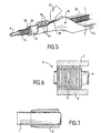
- Figure 5 is a perspective view at more large scale of part of the installation in Fig. 4
- Figure 6 shows, part in longitudinal section and partly outside, the tubular complex of a plastic foam shell, sheath ringed located inside this envelope and a tube housed in the sheath.
- Figure 7 is a diagram illustrating the compression of the foam shell to release the end of the inner tube.
- a tube 1 in particular in crosslinked PE (crosslinked polyethylene) flexible, which can be used to the supply of heat transfer fluid, generally of water, of thermal function devices such as fan coil units, or underfloor heating manifolds for living quarters, offices, etc ..., but also for hot water distribution systems or sanitary cold.
- PE crosslinked polyethylene
- a strip 2 of plastic foam is intended to surround the tube 1 with a slight tightening.
- the length of strip 2 is perpendicular to the plane of Fig. 1. Its width L is substantially equal to the perimeter of the section of the tube 1, slightly greater than this perimeter when subsequent treatments cause a narrowing of the width of the strip.
- band 2 along its width, around the tube 1 with a clamping relative of the tube and the edges are brought into contact longitudinal 2a, 2b of the strip.
- the two are then assembled by welding or gluing longitudinal edges 2a, 2b.
- the welding of the edges 2a, 2b is advantageously produced by blowing hot air using a nozzle B in a welding zone S.
- a nozzle B in a welding zone S.
- mirror welding the mirror consists of a electrically heated metal blade placed between the two edges 2a, 2b to be connected; when the temperature of welding is achieved, the mirror is removed and the two edges 2a, 2b, are applied one against the other.
- welding produces fusion and therefore elimination foam cells resulting in a narrowing.
- the glue enters cells of the foam and, as the foam is compressed on its edges in contact, the cells are frozen by gluing in the state tablet which produces a decrease in volume.
- the tightening is sufficient for the envelope of foam 2 around the tube 1 does not slip during installer manipulations.
- layer 2 foam should remain against the tube 1, without slipping, when the tube 1 is placed upright upright.
- the tightening not need to be too large in order to allow a installer to easily clear the end of the tube 1 in compressing, or releasing, the foam layer 2 on a certain length as illustrated in Fig. 7.
- Figure 4 illustrates in more detail the process for make a tubular complex C (Fig. 6) by combining three components, namely the outer casing 2 in plastic foam, a sheath 3 surrounded by this envelope, and a tube 4 located inside the sheath.
- the sheath 3 can be annealed as illustrated in Fig. 6.
- the tube 4 is advantageously made of crosslinked polyethylene while that the sheath 3 is generally made of polypropylene (PP).
- Such a set C is intended to be embedded in a concrete screed for the supply of heat transfer fluid, usually water, thermal appliances, or for supplying hot and cold water to devices sanitary facilities.
- the screed is attached to a full slab and made of cement mortar or concrete over a thickness about 6 to 15 cm.
- Envelope 2 in material foam plastic mainly has an insulation function thermal.
- the tube 4 like the sheath 3 and the casing 2, is flexible and can slide in the sheath 3 so that tube 4 can be replaced if necessary.
- Tube 4 can be inserted into a sheath 3 and an envelope 2 already embedded in a screed or slab.
- the sheath 3 surrounded by the foam envelope 2 may have inside, over its entire length, a wire tensile, in particular a steel wire. Setting subsequent placement of a heat transfer tube in such a sheath installed and covered with a screed is then facilitated, the wire used to pull the tube in the sheath.
- This sheath with wire, preferably corrugated, is generally designated by the expression "insulated needle sheath”. She is advantageously prepared in the form of crowns.
- a first reel 5 receives a reel 6 of sheath corrugated 3.
- This sheath 3 can be empty internally or contain a tube 4 of crosslinked polyethylene.
- Another reel 7 is provided with a reel 8 of a strip 2 of insulating foam, the axis of rotation of the two reels 5 and 7 being parallel.
- the strip 2 is unwound under the sheath 3 against it.
- the whole is drawn, from right to left in Fig. 4, by a puller 9 comprising two tracks which tighten between them the strip 2 and the sheath 3 and which rotate in the proper direction to ensure training.
- a device 10 Downstream of the printer 9 is provided a device 10 funnel-shaped with guide surfaces inclined and raised forming ramps to apply the band 2 around the sheath 3.
- the device 10 comprises, at its upper part, a longitudinal slot 11 at right of the support line of the edges 2a, 2b of the strip 2 which therefore remain accessible from the outside.
- a device of welding 12 for example a welding nozzle blowing hot air, is provided at the right of the slot 11 for the meeting edges 2a, 2b.
- the solder can be formed by a hot metal blade, also called mirror, arranged between the edges to welded.
- rollers 13, 14 Downstream of the welding device 12, the slot 11 widens to allow rollers 13, 14 to enter contact with the upper surface of the envelope 2, on either side of the weld line.
- three rollers 13, 14 are arranged on the side and other of the generator corresponding to the line of welding.
- the axes of the rollers 13, 14 are inclined on the direction of the weld line so as to form a acute angle facing downstream.
- Rollers 13, 14 help to apply edges 2a, 2b against each other the other.
- the part of the funnel 10, at the level of the rollers 12 and 13, is essentially cylindrical, indented in its upper part to allow the passage of the rollers.
- the foam envelope of plastic 2 containing the sheath 3 continues its progression on a support 15, formed by cylinders rotary, and passes under a marking device 16.
- Foam strip 2 is applied against the sheath 3 at a relatively low temperature so that it does not not stick to the sheath 3, or more generally to the element surrounded by this envelope 2. In the case where the sheath 3 is ringed, it exerts a braking action vis-à-vis of envelope 2. Such a braking effect is not as marked with a sheath with a smooth cylindrical surface.
- plastic foam extrusion in the form strip 2 near the element to be coated.
- Speed of scrolling of the element for example the sheath 3 is the same as the foam extrusion speed.
- the application extruded foam against the sheath 3 is produced when the foam is sufficiently cooled so that its temperature is acceptable by the sheath 3 in material thermoplastic such as polypropylene, etc.
- the foam shell 2 is not glued to the inner element (tube 1 or sheath 3), it is possible for an installer to push back or cut easily the foam wrap over a certain length to clear the inner tube for connection to a apparatus.
- the foam shell 2 in particular the weld edges 2a, 2b is made of waterproof material for prevent cement slag from entering the inside of this envelope when concrete is poured, because there would be loss of insulation.
- the foam wrap 2 and the sheath 3 also have the function of resisting crushing when the screed is poured.
- the foam envelope 2 can be made of polyurethane or in crosslinked polyethylene, or in non-crosslinked HDPE.
- crosslinked polyethylene In the case of a crosslinked polyethylene, the polyethylene is extruded in the non-crosslinked state, the foam containing the necessary ingredients, known, for the crosslinking. This crosslinking takes place in the layer of foam 2, shaping around the sheath 3 or element 1, by hydrolysis for example with ambient air.
- edges 2a, 2b when using for foam a crosslinked polyethylene or HDPE is provided by welding. If we use foam polyurethane, the edges 2a, 2b are assembled by gluing.
- the crowns 17 of the tubular complex C formed of tube 4 of crosslinked polyethylene, sheath 3 and envelope 2 can reach lengths of 200 meters.
- the length of the crowned complex is variable depending on the diameter of the heat pipe and can go from 10 meters for large diameters (greater than 50 mm) at 200 meters for the smallest diameters.
- the tube 4 When such an assembly is embedded in a slab or a concrete screed, the tube 4 is thermally insulated by envelope 2 of plastic foam and is protected mechanically by the sheath 3. The tube 4 can be pulled out and extracted by sliding in the sheath 3. Its replacement is ensured by pulling a new tube inside the sheath 3.
- the foam 2 is preferably of the cell type closed.
- the complex C constituted by the tube 4, the sheath 3 and the casing 2 is provided for winding in a crown along a radius of curvature of five times the diameter nominal of tube 4, without tearing or tearing of the foam 2.
- the hydro-wired system created with the complex tubular of the invention can be used for heating and / or cooling systems (radiators, convectors, fan coil units, air heaters ...) and for the distribution of hot or cold water health.
Landscapes
- Engineering & Computer Science (AREA)
- Mechanical Engineering (AREA)
- General Engineering & Computer Science (AREA)
- Manufacturing & Machinery (AREA)
- Chemical & Material Sciences (AREA)
- Combustion & Propulsion (AREA)
- Thermal Insulation (AREA)
- Lining Or Joining Of Plastics Or The Like (AREA)
- Packaging Of Annular Or Rod-Shaped Articles, Wearing Apparel, Cassettes, Or The Like (AREA)
- Laminated Bodies (AREA)
- Application Of Or Painting With Fluid Materials (AREA)
- Wrappers (AREA)
- Shaping Of Tube Ends By Bending Or Straightening (AREA)
- Materials For Medical Uses (AREA)
Abstract
Description
L'invention est relative à un procédé pour entourer une gaine en matière plastique pouvant contenir un tube qui peut être tiré dans cette gaine, par une couche de mousse de matière plastique, en particulier isolante thermiquement.The invention relates to a method for surround a plastic sheath that may contain a tube which can be drawn in this sheath, by a layer of foam plastic material, in particular thermally insulating.
Il est connu d'utiliser des tubes de cuivre enrobés de mousse de matière plastique. Toutefois, le tube de cuivre est rigide, ce qui pose des problèmes lors de l'installation. L'enrobage du tube de cuivre est généralement obtenu par coextrusion en tête d'équerre. Avec un tel procédé, la mousse de matière plastique colle fortement au tube. L'installateur, pour effectuer un raccordement, doit éliminer l'enrobage de mousse sur une certaine longueur, ce qui n'est pas aisé en raison de la forte adhérence de la mousse au tube. De plus, l'appareillage de coextrusion en tête d'équerre implique un investissement élevé.It is known to use copper tubes coated with plastic foam. However, the tube of copper is rigid, which causes problems when installation. The coating of the copper tube is generally obtained by square coextrusion. With such a process, the plastic foam sticks strongly to the tube. The installer, to carry out a connection, must remove the foam coating on a certain length, which is not easy due to the strong adhesion of the foam to the tube. Moreover, the square head coextrusion apparatus involves a high investment.
Lorsqu'un tel tube de cuivre enrobé de mousse est noyé dans une dalle ou une chape de béton ( par exemple pour l'alimentation en fluide caloporteur d'appareils à fonction thermique comme des ventilo-convecteurs ou des collecteurs d'un chauffage au sol pour des locaux d'habitation, des bureaux, etc.), il n'est pas possible de remplacer le tube par simple tirage. En effet, la coextrusion en tête d'équerre implique des températures élevées (de l'ordre de 180°C - 200°C) pour l'application de la mousse, ce qui ne permet pas de placer une gaine thermoplastique entre le tube de cuivre et la mousse de façon à permettre un échange du tube de cuivre par tirage en cas de besoin .When such a foam-coated copper tube is embedded in a concrete slab or screed (for example for supplying heat transfer fluid to thermal function such as fan coil units or floor heating collectors for premises living space, offices, etc.), it is not possible to replace the tube by simple pulling. Indeed, the square coextrusion implies temperatures high (around 180 ° C - 200 ° C) for the application of foam, which does not allow to place a sheath thermoplastic between the copper tube and the foam so as to allow an exchange of the copper tube by drawing if needed .
La possibilité de remplacer le tube est importante. Si le tube ne peut pas être remplacé, il fait partie de la garantie décennale ce qui entraíne une assurance coûteuse ; par contre, si le tube peut être remplacé, la garantie est biennale et entraíne une assurance moins coûteuse.The possibility of replacing the tube is important. If the tube cannot be replaced, it makes part of the ten-year guarantee which leads to expensive insurance; on the other hand, if the tube can be replaced, the warranty is biennial and results in less expensive insurance.
Avec le procédé en tête d'équerre, si l'on veut que la mousse ne colle pas trop au tube qui défile, il faut prévoir un corps intermédiaire à l'interface mousse / tube, tel qu'une graisse ou une huile silicone, ce qui n'est pas facile à réaliser.With the square head process, if you want that the foam does not stick too much to the running tube, provide an intermediate body at the foam / tube interface, such as grease or silicone oil, which is not easy to make.
Le procédé en tête d'équerre est en outre gourmand en énergie car le tube à recouvrir défile dans l'équerre et évacue des calories.The square head process is also greedy in energy because the tube to be covered scrolls in the square and removes calories.
On connaít d'après FR 2 372 690 un procédé pour la
fabrication de tubes équipés d'une enveloppe isolante en
mousse synthétique. Une bande de mousse synthétique est
déroulée à partir d'une bobine et est réchauffée puis mise
en forme dans une sorte d'entonnoir, en laissant toutefois
subsister un espace constituant un joint de l'ébauche. Le
tube est tiré d'une bobine et introduit par le joint
ménagé sur l'ébauche. Selon un tel procédé la bande est
pré-formée avec un réchauffage de sa paroi interne : ce
réchauffage peut provoquer un collage contre la paroi
interne empêchant toute possibilité de glissement de
l'enveloppe formée par la bande, relativement au tube ainsi
entouré. En outre la mise en place du tube dans l'ébauche
apparaít délicate, notamment dans le cas d'un élément
tubulaire de diamètre relativement important, tel qu'une
gaine dans laquelle un tube peut être tiré.We know from
JP 59 230721 concerne un procédé pour entourer un tube par une bande de mousse de matière plastique; une couche extérieure est extrudée autour de l'ensemble du tube et de son enveloppe en mousse. Il sera donc difficile de repousser ou de découper l'enveloppe de mousse puisqu'il faudra, au préalable, dégager la couche extérieure. En outre, aucun glissement de la couche de mousse relativement au tube n'apparaít possible.JP 59 230721 relates to a method for surrounding a tube by a strip of plastic foam; a outer layer is extruded around the entire tube and its foam envelope. It will therefore be difficult to push back or cut the foam envelope since you will first have to clear the outer layer. In furthermore, no sliding of the foam layer relatively to the tube does not appear possible.
DE 1915768 A concerne un procédé et un dispositif pour fabriquer des objets tabulaires à partir d'une mousse de résine thermoplastique. On part d'une bande de mousse et on l'enroule autour d'un axe longitudinal, avec chauffage des bords pour les souder. Dans une variante , un noyau cylindrique est prévu pour la phase d'enroulement. Si le noyau est flexible , il peut être extrait du tube par une fente. Il est aussi possible de conserver le noyau constitué par exemple d'un tube de cuivre. Une couche de matière isolante thermiquement peut en outre être prévue. Aucune indication n'est fournie pour éviter l'adhérence de l'enveloppe de mousse au tube intérieur.DE 1915768 A relates to a method and a device to make tabular objects from foam of thermoplastic resin. We start with a strip of foam and we wrap it around a longitudinal axis, with heating the edges to weld them. In a variant, a cylindrical core is provided for the winding phase. Yes the core is flexible, it can be extracted from the tube by a slit. It is also possible to keep the nucleus consisting for example of a copper tube. A layer of thermally insulating material may also be provided. No indication is provided to avoid adhesion of the foam wrap to the inner tube.
L'invention a pour but de fournir un procédé pour entourer une gaine par une couche de mousse de matière plastique qui permette d'éviter une adhérence trop élevée de la couche à l'élément. Il est souhaitable que le procédé permette aussi d'éviter des températures élevées pour l'application de la mousse de telle sorte que cette dernière puisse être utilisée autour de gaines en matière thermoplastique, en particulier d'une gaine pouvant contenir un tube qui peut être tiré dans la gaine.The object of the invention is to provide a process for surrounding a sheath by a layer of plastic foam which allows avoid too high adhesion of the layer to item. It is desirable that the process also allows avoid high temperatures when applying the foam so that it can be used around sheaths in thermoplastic material, in particular of a sheath which can contain a tube which can be pulled into the sheath.
Il convient en outre que le procédé soit économique et d'une mise en oeuvre simple et fiable.The process should also be economical and simple and reliable to use.
Ce tout est atteint par le procédé de la revendication 1. This is all achieved by the method of
Avantageusement, la gaine est annelée. De préférence, l'enveloppe de mousse est réalisée étanche aux laitiers de ciment. La gaine peut être en polychlorure de vinyle (PVC), ou polypropylène (PP) ou polyéthylène(PE).Advantageously, the sheath is corrugated. Of preferably, the foam envelope is made waterproof cement slag. The sheath may be made of polychloride of vinyl (PVC), or polypropylene (PP) or polyethylene (PE).
Le procédé se déroule en continu. Pour cela, on fait défiler la gaine, on fait défiler la bande à la même vitesse , on réalise l'application de la bande autour de la gaine en un emplacement déterminé et, en aval de cet emplacement, on réalise le soudage ou le collage des bords longitudinaux de la bande.The process takes place continuously. For that, we scroll the sheath, we scroll the tape at the same speed, we apply the tape around the duct at a specific location and, downstream of this location, welding or bonding of edges longitudinal of the strip.
La bande peut être préparée par extrusion de mousse à proximité de la gaine à entourer.Tape can be prepared by foam extrusion near the sheath to be surrounded.
La gaine à entourer et la bande sont avantageusement tirées en appui l'une contre l'autre, en particulier à partir de bobines qui sont déroulées, et la bande est appliquée autour de la gaine en traversant un dispositif en forme d' entonnoir comportant une fente longitudinale dans une zone correspondant aux bords longitudinaux en appui de la bande ; les bords de la bande sont soudés au droit de cette fente , tandis que des rouleaux de contact sont prévus en aval de la zone de soudure.The sheath to be surrounded and the band are advantageously drawn in abutment against one another, in particular from reels that are unwound, and the tape is applied around the sheath crossing a funnel-shaped device having a slit longitudinal in an area corresponding to the edges longitudinal in support of the strip; the edges of the strip are welded to the right of this slot, while contact rollers are provided downstream of the welding.
La gaine peut contenir un tube , en particulier en polyéthylène réticulé, qui peut être tiré dans cette gaine.The sheath may contain a tube, in particular in cross-linked polyethylene, which can be pulled through this sheath.
Le soudage des bords de la bande de mousse peut être réalisé par soufflage d'air chaud.Welding the edges of the foam strip can be made by blowing hot air.
La bande de mousse peut être en mousse de polyuréthane ou en mousse de PEHD (polyéthylène haute densité) non réticulé.The foam strip may be of foam polyurethane or HDPE foam (high polyethylene density) not crosslinked.
En variante, la bande de mousse est en PE (polyéthylène) extrudé à l'état non réticulé, avec ingrédients nécessaires à la réticulation, laquelle se produit dans la bande de mousse mise en forme, par hydrolyse, par exemple à l'air ambiant.Alternatively, the foam strip is made of PE (polyethylene) extruded in the non-crosslinked state, with ingredients necessary for crosslinking, which is produced in the shaped foam strip, by hydrolysis, for example with ambient air.
L'invention concerne également un complexe
tubulaire tel que décrit dans la revendication 13, comportant une enveloppe en mousse de matière
plastique et, à l'intérieur de l'enveloppe, une gaine en
matière plastique serrée sans collage de l'enveloppe, la
gaine pouvant contenir un tube qui peut être tiré dans
cette gaine.The invention also relates to a complex
tubular as described in
La gaine peut comporter à l'intérieur, sur toute sa longueur, un fil de traction, en particulier un fil d'acier.The sheath may have inside, on all of its length, a traction wire, in particular a wire steel.
Le complexe tubulaire peut comporter en outre un tube disposé à l'intérieur de la gaine dans laquelle il peut coulisser.The tubular complex may further include a tube placed inside the sheath in which it can slide.
L'enveloppe en mousse peut avoir été obtenue par un procédé tel que défini précédemment.The foam envelope may have been obtained by a process as defined above.
Le serrage exercé par l'enveloppe de mousse est suffisant pour que la gaine ne glisse pas lors des manipulations d'un installateur, en particulier suffisant pour que l'enrobage de mousse reste en place lorsque la gaine est disposée debout.The tightness exerted by the foam envelope is sufficient so that the sheath does not slip during manipulations of an installer, in particular sufficient so that the foam coating stays in place when the sheath is arranged upright.
L'invention consiste, mises à part les dispositions exposées ci-dessus, en un certain nombre d'autres dispositions dont il sera plus explicitement question ci-après à propos d'exemples de réalisation décrits avec référence aux dessins ci-annexés, mais qui ne sont nullement limitatifs.The invention consists, apart from the provisions set out above, in a number of others provisions which will be more explicitly discussed below about exemplary embodiments described with reference to the attached drawings, but which are not in no way limiting.
La figure 1, de ces dessins, est une vue en bout d'un tube et d'une bande de mousse qui va servir à entourer le tube.Figure 1 of these drawings is an end view a tube and a strip of foam that will be used to surround the tube.
La figure 2 est une vue également en bout du tube entouré de la bande de mousse dont les bords longitudinaux sont en cours de soudage.Figure 2 is a view also at the end of the tube surrounded by the strip of foam whose longitudinal edges are being welded.
La figure 3 est une vue schématique en plan de l'enrobage du tube par la bande et de la zone de soudage des bords. Figure 3 is a schematic plan view of the coating of the tube by the strip and of the welding zone edges.
La figure 4 est une vue schématique en élévation d'une installation pour la mise en oeuvre du procédé selon l'invention.Figure 4 is a schematic elevational view an installation for implementing the method according to the invention.
La figure 5 est une vue en perspective à plus grande échelle d'une partie de l'installation de Fig.4Figure 5 is a perspective view at more large scale of part of the installation in Fig. 4
La figure 6 montre, partie en coupe longitudinale et partie en extérieur, le complexe tubulaire d'une enveloppe en mousse de matière plastique, d'une gaine annelée située à l'intérieur de cette enveloppe et d'un tube logé dans la gaine.Figure 6 shows, part in longitudinal section and partly outside, the tubular complex of a plastic foam shell, sheath ringed located inside this envelope and a tube housed in the sheath.
La figure 7, enfin, est un schéma illustrant la compression de l'enveloppe de mousse pour dégager l'extrémité du tube intérieur.Figure 7, finally, is a diagram illustrating the compression of the foam shell to release the end of the inner tube.
En se reportant à la figure 1 des dessins, on peut
voir un tube 1 , en particulier en PE réticulé
(polyéthylène réticulé) flexible, pouvant servir à
l'alimentation en fluide caloporteur, généralement de
l'eau, d'appareils à fonction thermique comme des ventilo-convecteurs,
ou des collecteurs d'un chauffage au sol pour
des locaux d'habitation, des bureaux, etc..., mais aussi
pour des installations de distribution d'eau chaude ou
froide sanitaire.Referring to Figure 1 of the drawings, one can
see a
Une bande 2 de mousse de matière plastique est
prévue pour entourer le tube 1 avec un léger serrage. La
longueur de la bande 2 est perpendiculaire au plan de
Fig. 1. Sa largeur L est sensiblement égale au périmètre de
la section du tube 1, légèrement supérieure à ce périmètre
lorsque les traitements ultérieurs provoquent un
rétrécissement de la largeur de la bande.A
Comme illustré sur Fig.2, on applique la bande 2,
suivant sa largeur, autour du tube 1 avec un serrage
relatif du tube et on met en contact les bords
longitudinaux 2a , 2b de la bande.As illustrated in Fig. 2, we apply
On assemble ensuite par soudage ou collage les deux
bords longitudinaux 2a, 2b.The two are then assembled by welding or gluing
La soudure des bords 2a, 2b, est avantageusement
réalisée par un soufflage d'air chaud à l'aide d'une buse B
dans une zone S de soudage. En variante, on peut utiliser
une " soudure au miroir " ; le miroir est constitué par une
lame métallique chauffée électriquement et placée entre les
deux bords 2a, 2b à raccorder ; quand la température de
soudage est atteinte, le miroir est enlevé et les deux
bords 2a, 2b, sont appliqués l'un contre l'autre.The welding of the
Il est également possible de réaliser l'assemblage
des deux bords 2a, 2b par collage. Dans ce cas on peut
mettre en place dans la zone S un compte-gouttes doseur
alimenté en colle contact, par exemple du type isocyanate.
Les gouttes de colle tombent entre les bords 2a, 2b en
cours de rapprochement et se font écraser par ces bords 2a,
2b lorsqu'ils viennent en contact ce qui provoque le
collage.It is also possible to carry out the assembly
of the two
Le soudage produit une fusion et donc l'élimination de cellules de mousse d'où un rétrécissement. Dans le cas d'un collage, la colle rentre dans des cellules de la mousse et, comme la mousse est comprimée sur ses bords en contact, les cellules sont figées par collage à l'état comprimé ce qui produit une diminution de volume.Welding produces fusion and therefore elimination foam cells resulting in a narrowing. In the case of a collage, the glue enters cells of the foam and, as the foam is compressed on its edges in contact, the cells are frozen by gluing in the state tablet which produces a decrease in volume.
Le serrage du tube 1, et plus généralement de
l'élément cylindrique ou prismatique entouré par la couche
de mousse 2, prend en compte ces effets.The tightening of the
Le serrage est suffisant pour que l'enveloppe de
mousse 2 autour du tube 1 ne glisse pas lors des
manipulations de l'installateur. En particulier la couche 2
de mousse doit rester contre le tube 1, sans glisser,
lorsque le tube 1 est placé debout vertical. Le serrage n'a
pas besoin d'être trop important afin de permettre à un
installateur de dégager facilement l'extrémité du tube 1 en
comprimant, ou en dégageant, la couche de mousse 2 sur une
certaine longueur comme illustré sur Fig.7.The tightening is sufficient for the envelope of
La figure 4 illustre plus en détail le procédé pour
réaliser un complexe tubulaire C (Fig.6) par association de
trois composants, à savoir l'enveloppe 2 extérieure en
mousse de matière plastique, une gaine 3 entourée par cette
enveloppe, et un tube 4 situé à l'intérieur de la gaine. La
gaine 3 peut être annelée comme illustré sur Fig.6 . Le
tube 4 est avantageusement en polyéthylène réticulé tandis
que la gaine 3 est généralement en polypropylène (PP).Figure 4 illustrates in more detail the process for
make a tubular complex C (Fig. 6) by combining
three components, namely the
Un tel ensemble C est destiné à être noyé dans une
chape de béton pour l'alimentation en fluide caloporteur,
généralement de l'eau, d'appareils à fonction thermique, ou
pour l'alimentation en eau chaude et froide d'appareils
sanitaires . La chape est rapportée sur une dalle pleine et
réalisée en mortier de ciment ou en béton sur une épaisseur
d'environ 6 à 15 cm. L'enveloppe 2 en mousse de matière
plastique a principalement une fonction d'isolation
thermique.Such a set C is intended to be embedded in a
concrete screed for the supply of heat transfer fluid,
usually water, thermal appliances, or
for supplying hot and cold water to devices
sanitary facilities. The screed is attached to a full slab and
made of cement mortar or concrete over a thickness
about 6 to 15 cm.
Le tube 4, comme la gaine 3 et l'enveloppe 2, est
flexible et peut coulisser dans la gaine 3 de sorte que ce
tube 4 peut être échangé si nécessaire. Le tube 4 peut être
introduit dans une gaine 3 et une enveloppe 2 déjà noyées
dans une chape ou une dalle.The tube 4, like the
La gaine 3 entourée par l'enveloppe 2 en mousse
peut comporter à l'intérieur, sur toute sa longueur, un fil
de traction, en particulier un fil d'acier. La mise en
place ultérieure d'un tube caloporteur dans une telle gaine
installée et recouverte par une chape est alors facilitée ,
le fil permettant de tirer le tube dans la gaine. Cette
gaine avec fil, de préférence annelée, est généralement
désignée par l'expression "gaine aiguillée isolée". Elle
est avantageusement préparée sous forme de couronnes.The
Pour réaliser l'ensemble C de Fig.6, on procède avantageusement comme illustré sur Figs.4 et 5.To make the set C in Fig. 6, we proceed advantageously as illustrated in Figs. 4 and 5.
Un premier dévidoir 5 reçoit une bobine 6 de gaine
annelée 3. Cette gaine 3 peut être vide intérieurement ou
contenir un tube 4 de polyéthylène réticulé.A first reel 5 receives a reel 6 of sheath
corrugated 3. This
Un autre dévidoir 7 est muni d'une bobine 8 d'une
bande 2 de mousse isolante, l'axe de rotation des deux
dévidoirs 5 et 7 étant parallèles.Another reel 7 is provided with a reel 8 of a
La bande 2 est déroulée sous la gaine 3 contre
celle-ci. L'ensemble est tiré, de la droite vers la gauche
de Fig.4, par une tireuse 9 comportant deux chenilles qui
serrent entre elles la bande 2 et la gaine 3 et qui
tournent dans le sens convenable pour assurer
l'entraínement.The
En aval de la tireuse 9 est prévu un dispositif 10
en forme d'entonnoir qui comporte des surfaces de guidage
inclinées et relevées formant des rampes pour appliquer la
bande 2 autour de la gaine 3. Le dispositif 10 comporte, à
sa partie supérieure, une fente longitudinale 11 au droit
de la ligne d'appui des bords 2a, 2b de la bande 2 qui
restent donc accessibles depuis l'extérieur. Un dispositif
de soudure 12, par exemple une buse de soudure soufflant de
l'air chaud, est prévu au droit de la fente 11 pour la
réunion des bords 2a, 2b. En variante, le dispositif de
soudure peut être constitué par une lame métallique chaude,
également appelée miroir, disposée entre les bords à
souder.Downstream of the printer 9 is provided a
En aval du dispositif de soudure 12, la fente 11
s'élargit pour permettre à des rouleaux 13, 14 d'entrer en
contact avec la surface supérieure de l'enveloppe 2, de
part et d'autre de la ligne de soudure. Sur le schéma de
Fig.5, trois rouleaux 13, 14 sont disposés de part et
d'autre de la génératrice correspondant à la ligne de
soudure. Les axes des rouleaux 13, 14 sont inclinés sur la
direction de la ligne de soudure de manière à former un
angle aigu tourné vers l'aval. Les rouleaux 13, 14
contribuent à appliquer les bords 2a, 2b l'un contre
l'autre. La partie de l'entonnoir 10, au niveau des
rouleaux 12 et 13, est essentiellement cylindrique,
échancrée dans sa partie supérieure pour permettre le
passage des rouleaux.Downstream of the
A la sortie de l'entonnoir 10 l'enveloppe de mousse
de matière plastique 2 contenant la gaine 3 continue sa
progression sur un support 15, formé par des cylindres
rotatifs, et passe sous un dispositif de marquage 16.At the exit of the
Le complexe tubulaire constitué par la gaine 3,
contenant éventuellement le tube 4, entourée par
l'enveloppe 2, est mis sous forme de couronne 17 sur un
enrouleur 18. The tubular complex constituted by the
La bande de mousse 2 est appliquée contre la gaine
3 à une température relativement faible de sorte qu'elle ne
colle pas à la gaine 3, ou plus généralement à l'élément
entouré par cette enveloppe 2. Dans le cas où la gaine 3
est annelée, elle exerce une action de freinage vis-à-vis
de l'enveloppe 2. Un tel effet de freinage n'est pas aussi
marqué avec une gaine à surface cylindrique lisse.
En variante, au lieu d'alimenter la bande 2 sous
forme de bobine 8 comme illustré sur Fig.4, on peut prévoir
une extrusion de la mousse de matière plastique sous forme
de bande 2 à proximité de l'élément à enrober. La vitesse
de défilement de l'élément, par exemple la gaine 3, est la
même que la vitesse d'extrusion de la mousse. L'application
de la mousse extrudée contre la gaine 3 est réalisée
lorsque la mousse est suffisamment refroidie pour que sa
température soit acceptable par la gaine 3 en matière
thermoplastique tel que polypropylène, , etc.Alternatively, instead of feeding the
Du fait que l'enveloppe de mousse 2 n'est pas
collée sur l'élément intérieur (tube 1 ou gaine 3 ), il est
possible pour un installateur de repousser ou de découper
facilement l'enveloppe de mousse sur une certaine longueur
pour dégager le tube intérieur en vue du raccordement à un
appareil.Because the
L'enveloppe de mousse 2, en particulier la soudure
des bords 2a, 2b est réalisée de matière étanche pour
éviter que des laitiers de ciment ne pénètrent à
l'intérieur de cette enveloppe lorsque du béton est coulé,
car il y aurait perte d'isolation. L'enveloppe de mousse 2
et la gaine 3 ont également pour fonction de résister à
l'écrasement lorsque la chape est coulée.The
L'enveloppe de mousse 2 peut être en polyuréthane
ou en polyéthylène réticulé, ou en PEHD non réticulé.The
Dans le cas d'un polyéthylène réticulé, le
polyéthylène est extrudé à l'état non réticulé, la mousse
contenant les ingrédients nécessaires, connus, à la
réticulation. Cette réticulation se fait dans la couche de
mousse 2, mise en forme autour de la gaine 3 ou de
l'élément 1, par hydrolyse par exemple à l'air ambiant.In the case of a crosslinked polyethylene, the
polyethylene is extruded in the non-crosslinked state, the foam
containing the necessary ingredients, known, for the
crosslinking. This crosslinking takes place in the layer of
L'assemblage des bords 2a, 2b lorsqu'on utilise
pour la mousse un polyéthylène réticulé ou un PEHD, est
assuré par soudure. Si on utilise une mousse de
polyuréthane, les bords 2a, 2b sont assemblés par collage.The assembly of the
Les couronnes 17 du complexe tubulaire C formé du
tube 4 de polyéthylène réticulé, de la gaine 3 et de
l'enveloppe 2 peuvent atteindre des longueurs de 200
mètres. La longueur du complexe mis en couronne est
variable selon le diamètre du tube caloporteur et peut
aller de 10 mètres pour les gros diamètres ( supérieurs à
50 mm) à 200 mètres pour les plus petits diamètres.The
Lorsqu'un tel ensemble est noyé dans une dalle ou
une chape de béton, le tube 4 est isolé thermiquement par
l'enveloppe 2 de mousse de matière plastique et est protégé
mécaniquement par la gaine 3. Le tube 4 peut être tiré et
extrait par coulissement dans la gaine 3. Son remplacement
est assuré en tirant un tube neuf à l'intérieur de la gaine
3.When such an assembly is embedded in a slab or
a concrete screed, the tube 4 is thermally insulated by
La mousse 2 est de préférence du type à cellules
fermées. Le complexe C constitué par le tube 4, la gaine 3
et l'enveloppe 2 est prévu pour un enroulement en couronne
suivant un rayon de courbure de cinq fois le diamètre
nominal du tube 4, sans arrachement ni déchirure de la
mousse 2.The
Le système hydrocablé réalisé avec le complexe tubulaire de l'invention peut être utilisé pour des installations de chauffage et/ou de rafraíchissement (radiateurs, convecteurs, ventilo-convecteurs, aérothermes...) et pour la distribution des eaux chaudes ou froides sanitaires.The hydro-wired system created with the complex tubular of the invention can be used for heating and / or cooling systems (radiators, convectors, fan coil units, air heaters ...) and for the distribution of hot or cold water health.
Claims (20)
- Process for wrapping a plastic sheath (3), able to contain a tube (4) that can be pulled into this sheath, with a layer of plastic foam, in particular one which is thermally insulating, in which a foam strip (2) is prepared whose width (L) is substantially equal to the perimeter of the cross section of the element (1, 3) to be wrapped, the strip (2) is applied, across its width, around the element and the two longitudinal edges (2a, 2b) of the strip are joined together by welding or adhesive bonding, in which process the strip (2) is applied against the sheath (3) at a relatively low temperature so that it does not bond to the sheath (3), and with relative gripping of the sheath, by bringing the longitudinal edges (2a, 2b) of the strip into contact with each other, the gripping exerted by the foam wrapper being sufficient for the wrapped sheath (3) not to slip when being handled by an installer, in particular sufficient for the foam covering to remain in place when the sheath is placed upright.
- Process according to Claim 1, characterized in that the sheath (3) is annulate.
- Process according to Claim 1 or 2, characterized in that the foam wrapper is made impermeable to cement slurries.
- Process according to one of Claims 1 to 3, characterized in that the sheath (3) is made of PVC, PP or PE.
- Process according to one of Claims 1 to 4, characterized in that it is carried out continuously.
- Process according to Claim 5, characterized in that the sheath (3) is made to run, the strip (2) is made to run at the same speed, the strip is applied around the sheath at a defined point (10) and, downstream of this point, the longitudinal edges (2a, 2b) of the strip are welded or adhesively bonded together.
- Process according to Claim 6, characterized in that the strip is prepared by foam extrusion near the sheath to be wrapped.
- Process according to Claim 6 or 7, characterized in that the sheath (3) to be wrapped and the strip (2) are pulled, so as to bear against each other, in particular from wheels (6, 8) that are unwound, and the strip (2) is applied around the sheath (3) by passing through a funnel-shaped device (10) having a longitudinal slot (11) in a region corresponding to the place where the longitudinal edges of the strip bear against each other, the edges (2a, 2b) of the strip being welded together in line with this slot (11).
- Process according to Claim 8, characterized in that contact rollers (13, 14) are provided downstream of the welding region.
- Process according to one of the preceding claims, characterized in that the edges (2a, 2b) of the foam strip are welded together by blowing hot air.
- Process according to one of the preceding claims, characterized in that the foam strip (2) is made of an uncrosslinked HDPE (high-density polyethylene) foam or polyurethane foam.
- Process according to one of Claims 1 to 10, characterized in that the foam strip (2) is made of PE (polyethylene) extruded in the uncrosslinked state, with necessary ingredients for the crosslinking, which crosslinking takes place in the formed foam strip by hydrolysis, for example in the ambient air.
- Tubular complex, characterized in that it comprises a plastic foam wrapper (2) and, inside the wrapper, a plastic sheath (3) gripped, with no bonding, by the wrapper, the sheath possibly containing a tube (4) that can be pulled into this sheath.
- Tubular complex according to Claim 13, characterized in that the wrapper (2) has a join line, where the edges (2a, 2b) are joined together by welding or adhesive bonding, along a generatrix.
- Tubular complex according to Claim 13 or 14, characterized in that the sheath (3) has, inside, over its entire length, a pull wire, in particular a steel wire.
- Tubular complex according to Claim 13 or 14, characterized in that a tube (4) is placed inside the sheath, in which the tube can slide.
- Tubular complex according to one of Claims 13 to 16, characterized in that the sheath (3) is annulate.
- Tubular complex according to Claim 16, characterized in that the tube (4) is made of crosslinked polyethylene.
- Tubular complex according to one of Claims 13 to 18, characterized in that the gripping exerted by the foam wrapper is sufficient for the wrapped sheath (3) not to slip when being handled by an installer, in particular sufficient for the foam covering to remain in place when the sheath is placed upright.
- Tubular complex according to one of Claims 14 to 19, in which the foam wrapper has been obtained by a process according to one of Claims 1 to 12.
Applications Claiming Priority (4)
| Application Number | Priority Date | Filing Date | Title |
|---|---|---|---|
| FR9913879 | 1999-11-05 | ||
| FR9913879A FR2800664A1 (en) | 1999-11-05 | 1999-11-05 | Economical, installer-friendly sheathing of copper pipes with insulating foam is carried out by continuous longitudinal wrapping and edge-adhesion under slight pressure |
| FR0000254A FR2800665B1 (en) | 1999-11-05 | 2000-01-11 | METHOD FOR SURROUNDING AN ELEMENT WITH A FOAM LAYER, FOAM ENVELOPE, TUBULAR COMPLEX WITH THE SAME, AND CROWN THEREOF |
| FR0000254 | 2000-01-11 |
Publications (2)
| Publication Number | Publication Date |
|---|---|
| EP1097796A1 EP1097796A1 (en) | 2001-05-09 |
| EP1097796B1 true EP1097796B1 (en) | 2003-04-02 |
Family
ID=26212082
Family Applications (1)
| Application Number | Title | Priority Date | Filing Date |
|---|---|---|---|
| EP00403040A Expired - Lifetime EP1097796B1 (en) | 1999-11-05 | 2000-11-02 | Process for wrapping a sheath with a foam layer, and tubular complex with wrapped sheath |
Country Status (7)
| Country | Link |
|---|---|
| EP (1) | EP1097796B1 (en) |
| AT (1) | ATE236006T1 (en) |
| DE (1) | DE60001895T2 (en) |
| DK (1) | DK1097796T3 (en) |
| ES (1) | ES2195847T3 (en) |
| FR (1) | FR2800665B1 (en) |
| PT (1) | PT1097796E (en) |
Cited By (1)
| Publication number | Priority date | Publication date | Assignee | Title |
|---|---|---|---|---|
| US20210172549A1 (en) * | 2018-07-25 | 2021-06-10 | Jonathon Ivett | Connector assembly |
Families Citing this family (2)
| Publication number | Priority date | Publication date | Assignee | Title |
|---|---|---|---|---|
| KR100495376B1 (en) * | 2003-06-17 | 2005-06-14 | 박용길 | Jig of manufaturing apparatus pipe for air conditioning system |
| JP5847403B2 (en) * | 2011-03-01 | 2016-01-20 | 株式会社ブリヂストン | Manufacturing method of composite pipe |
Family Cites Families (9)
| Publication number | Priority date | Publication date | Assignee | Title |
|---|---|---|---|---|
| DE1915768C3 (en) * | 1968-03-27 | 1974-02-07 | The Furukawa Electric Co., Ltd., Tokio | A method and apparatus for continuously manufacturing a tubular article from a sheet of foamed thermoplastic resin |
| FR2225681B1 (en) * | 1973-04-13 | 1976-05-21 | Pont A Mousson | |
| DE7417030U (en) * | 1974-05-15 | 1974-10-03 | Kabel Und Metallwerke Gutehoffnungshuette Ag | FLEXIBLE PIPE FOR CONVEYING LIQUID OR GAS MEDIA |
| DE2654879C2 (en) * | 1976-12-03 | 1982-11-11 | Dynamit Nobel Ag, 5210 Troisdorf | Process for the continuous production of a pipe provided with an insulating sleeve made of foam plastic |
| DE3318082A1 (en) * | 1983-05-18 | 1984-11-22 | Dynamit Nobel Ag, 5210 Troisdorf | METHOD AND DEVICE FOR PRODUCING A TUBE PROVIDED WITH AN INSULATING COVER FROM FOAM |
| JPS59230721A (en) * | 1983-06-14 | 1984-12-25 | Dainichi Nippon Cables Ltd | Continuous manufacture of heat insulated pipe |
| FR2573275B1 (en) * | 1984-11-12 | 1987-02-13 | Bernard Francis | MACHINE AND METHOD FOR THREADING THREADS IN A CONDUIT |
| US4637756A (en) * | 1985-01-23 | 1987-01-20 | Boles Flounoy W | Apparatus for removing and replacing pipe beneath an earthfill |
| FR2689698B1 (en) * | 1992-04-03 | 1994-06-03 | Courant Ets Sa | INSULATING DUCT FOR THE PASSAGE OF AN ELECTRICAL OR SIMILAR CABLE. |
-
2000
- 2000-01-11 FR FR0000254A patent/FR2800665B1/en not_active Expired - Fee Related
- 2000-11-02 ES ES00403040T patent/ES2195847T3/en not_active Expired - Lifetime
- 2000-11-02 PT PT00403040T patent/PT1097796E/en unknown
- 2000-11-02 DK DK00403040T patent/DK1097796T3/en active
- 2000-11-02 DE DE60001895T patent/DE60001895T2/en not_active Expired - Lifetime
- 2000-11-02 EP EP00403040A patent/EP1097796B1/en not_active Expired - Lifetime
- 2000-11-02 AT AT00403040T patent/ATE236006T1/en not_active IP Right Cessation
Cited By (2)
| Publication number | Priority date | Publication date | Assignee | Title |
|---|---|---|---|---|
| US20210172549A1 (en) * | 2018-07-25 | 2021-06-10 | Jonathon Ivett | Connector assembly |
| US11680666B2 (en) * | 2018-07-25 | 2023-06-20 | FlexiGas UKC Ltd | Connector assembly |
Also Published As
| Publication number | Publication date |
|---|---|
| ATE236006T1 (en) | 2003-04-15 |
| DE60001895T2 (en) | 2004-02-05 |
| EP1097796A1 (en) | 2001-05-09 |
| FR2800665A1 (en) | 2001-05-11 |
| FR2800665B1 (en) | 2002-08-30 |
| DK1097796T3 (en) | 2003-07-28 |
| DE60001895D1 (en) | 2003-05-08 |
| ES2195847T3 (en) | 2003-12-16 |
| PT1097796E (en) | 2003-07-31 |
Similar Documents
| Publication | Publication Date | Title |
|---|---|---|
| EP0069020B1 (en) | Plastics device for perforating a plastics element placed below it, process for producing the device and its use in the production of pipe branchings | |
| BE1001865A4 (en) | Method and device for producing continuous foam shell on solid and hollow profiles profiles or obtained. | |
| FR2484162A1 (en) | DEVICE FOR SEALING A COAXIAL SUBMARINE CABLE TO A REPEATER, METHOD FOR MANUFACTURING THE SAME, AND MOLD FOR USE THEREIN | |
| FR2743402A1 (en) | BRAIDED SHEATH SLEEVE FOR THREADING ON AT LEAST ONE ELONGATE MEMBER TO BE PROTECTED, AND METHOD FOR MANUFACTURING SUCH A SLEEVE | |
| FR2752904A1 (en) | METHOD FOR MANUFACTURING A FLEXIBLE DRIVE | |
| CH660223A5 (en) | DEVICE AND METHOD FOR SEALING TIPED ENDS OR SECTIONS OF PIPES. | |
| FR2588353A1 (en) | CONNECTION IN PARTICULAR FOR TUBES AND PIPES | |
| EP1097796B1 (en) | Process for wrapping a sheath with a foam layer, and tubular complex with wrapped sheath | |
| FR2516443A1 (en) | METHOD AND DEVICE FOR MANUFACTURING A COMPLEX PIPE | |
| EP0402201A2 (en) | Wire with shaped coating, especially for making an electro-fusion insert | |
| FR2703817A1 (en) | Support member for an elastic sleeve and elastic sleeve maintained in an expanded state by a removable support member. | |
| EP0872749A1 (en) | Method of fabrication of a fibre optic cable and cable obtained by this method | |
| FR2800664A1 (en) | Economical, installer-friendly sheathing of copper pipes with insulating foam is carried out by continuous longitudinal wrapping and edge-adhesion under slight pressure | |
| FR2606857A1 (en) | THERMALLY INSULATED PIPE TUBE CONSISTING OF TWO CONCENTRIC TUBES WRAPPED IN REDUCED DIAMETER ANNULAR BOOTS | |
| BE1008956A3 (en) | Method of manufacturing a pipe based plastic industry and pipe extrusion. | |
| FR2704070A1 (en) | Installation and method of manufacturing a fiber optic cable. | |
| FR2664850A1 (en) | Method of sheathing a bundle of filiform elements, device for implementing it and bundle obtained | |
| FR2523264A1 (en) | PROCESS FOR THE MANUFACTURE OF A THERMALLY INSULATED PIPING FOR WATER DISTRIBUTION OR HEATING PLANTS | |
| FR2627026A1 (en) | Method of sealing between a cable or similar element and an external duct receiving this cable, and composite tape for implementing this method | |
| EP0105068B1 (en) | Electrical plastic welding sleeve and method for its manufacture | |
| LU86432A1 (en) | METHOD OF LAYING AND PULLING A CABLE IN A CONDUIT AND DEVICE USING THE SAME | |
| FR2535570A1 (en) | Electrical heating strip for producing a sleeve junction for thermally insulated tubular piping, and its method of manufacture. | |
| FR2787548A1 (en) | COMPOSITE FLEXIBLE FOR TRANSPORTING FLUID AND MANUFACTURING METHOD THEREOF | |
| EP0687850B1 (en) | Thermal insulating covering for a pipeline and method for manufacturing the same | |
| FR2670058A1 (en) | DEVICE FOR PROTECTING A CABLE CONNECTION. |
Legal Events
| Date | Code | Title | Description |
|---|---|---|---|
| PUAI | Public reference made under article 153(3) epc to a published international application that has entered the european phase |
Free format text: ORIGINAL CODE: 0009012 |
|
| 17P | Request for examination filed |
Effective date: 20001108 |
|
| AK | Designated contracting states |
Kind code of ref document: A1 Designated state(s): AT BE CH CY DE DK ES FI FR GB GR IE IT LI LU MC NL PT SE TR |
|
| AX | Request for extension of the european patent |
Free format text: AL;LT;LV;MK;RO;SI |
|
| AKX | Designation fees paid |
Free format text: AT BE CH CY DE DK ES FI FR GB GR IE IT LI LU MC NL PT SE TR |
|
| 17Q | First examination report despatched |
Effective date: 20020429 |
|
| GRAH | Despatch of communication of intention to grant a patent |
Free format text: ORIGINAL CODE: EPIDOS IGRA |
|
| RTI1 | Title (correction) |
Free format text: PROCESS FOR WRAPPING A SHEATH WITH A FOAM LAYER, AND TUBULAR COMPLEX WITH WRAPPED SHEATH |
|
| RTI1 | Title (correction) |
Free format text: PROCESS FOR WRAPPING A SHEATH WITH A FOAM LAYER, AND TUBULAR COMPLEX WITH WRAPPED SHEATH |
|
| GRAH | Despatch of communication of intention to grant a patent |
Free format text: ORIGINAL CODE: EPIDOS IGRA |
|
| GRAA | (expected) grant |
Free format text: ORIGINAL CODE: 0009210 |
|
| AK | Designated contracting states |
Designated state(s): AT BE CH CY DE DK ES FI FR GB GR IE IT LI LU MC NL PT SE TR |
|
| PG25 | Lapsed in a contracting state [announced via postgrant information from national office to epo] |
Ref country code: TR Free format text: LAPSE BECAUSE OF FAILURE TO SUBMIT A TRANSLATION OF THE DESCRIPTION OR TO PAY THE FEE WITHIN THE PRESCRIBED TIME-LIMIT Effective date: 20030402 Ref country code: AT Free format text: LAPSE BECAUSE OF FAILURE TO SUBMIT A TRANSLATION OF THE DESCRIPTION OR TO PAY THE FEE WITHIN THE PRESCRIBED TIME-LIMIT Effective date: 20030402 Ref country code: IE Free format text: LAPSE BECAUSE OF NON-PAYMENT OF DUE FEES Effective date: 20030402 |
|
| REG | Reference to a national code |
Ref country code: GB Ref legal event code: FG4D Free format text: NOT ENGLISH |
|
| REG | Reference to a national code |
Ref country code: CH Ref legal event code: EP |
|
| REG | Reference to a national code |
Ref country code: IE Ref legal event code: FG4D Free format text: FRENCH |
|
| REF | Corresponds to: |
Ref document number: 60001895 Country of ref document: DE Date of ref document: 20030508 Kind code of ref document: P |
|
| PG25 | Lapsed in a contracting state [announced via postgrant information from national office to epo] |
Ref country code: GR Free format text: LAPSE BECAUSE OF FAILURE TO SUBMIT A TRANSLATION OF THE DESCRIPTION OR TO PAY THE FEE WITHIN THE PRESCRIBED TIME-LIMIT Effective date: 20030702 |
|
| REG | Reference to a national code |
Ref country code: SE Ref legal event code: TRGR |
|
| REG | Reference to a national code |
Ref country code: DK Ref legal event code: T3 |
|
| GBT | Gb: translation of ep patent filed (gb section 77(6)(a)/1977) |
Effective date: 20030715 |
|
| PG25 | Lapsed in a contracting state [announced via postgrant information from national office to epo] |
Ref country code: LU Free format text: LAPSE BECAUSE OF NON-PAYMENT OF DUE FEES Effective date: 20031102 Ref country code: CY Free format text: LAPSE BECAUSE OF FAILURE TO SUBMIT A TRANSLATION OF THE DESCRIPTION OR TO PAY THE FEE WITHIN THE PRESCRIBED TIME-LIMIT Effective date: 20031102 |
|
| REG | Reference to a national code |
Ref country code: IE Ref legal event code: FD4D Ref document number: 1097796E Country of ref document: IE |
|
| PG25 | Lapsed in a contracting state [announced via postgrant information from national office to epo] |
Ref country code: MC Free format text: LAPSE BECAUSE OF NON-PAYMENT OF DUE FEES Effective date: 20031130 |
|
| REG | Reference to a national code |
Ref country code: ES Ref legal event code: FG2A Ref document number: 2195847 Country of ref document: ES Kind code of ref document: T3 |
|
| PLBE | No opposition filed within time limit |
Free format text: ORIGINAL CODE: 0009261 |
|
| STAA | Information on the status of an ep patent application or granted ep patent |
Free format text: STATUS: NO OPPOSITION FILED WITHIN TIME LIMIT |
|
| 26N | No opposition filed |
Effective date: 20040105 |
|
| PG25 | Lapsed in a contracting state [announced via postgrant information from national office to epo] |
Ref country code: CH Free format text: LAPSE BECAUSE OF NON-PAYMENT OF DUE FEES Effective date: 20041130 Ref country code: LI Free format text: LAPSE BECAUSE OF NON-PAYMENT OF DUE FEES Effective date: 20041130 |
|
| REG | Reference to a national code |
Ref country code: CH Ref legal event code: PL |
|
| REG | Reference to a national code |
Ref country code: FR Ref legal event code: TP |
|
| REG | Reference to a national code |
Ref country code: PT Ref legal event code: PC4A Owner name: COMP PLASTIC INDUSTRIES, FR Effective date: 20091118 |
|
| REG | Reference to a national code |
Ref country code: GB Ref legal event code: 732E Free format text: REGISTERED BETWEEN 20091203 AND 20091209 |
|
| PGFP | Annual fee paid to national office [announced via postgrant information from national office to epo] |
Ref country code: FI Payment date: 20091112 Year of fee payment: 10 Ref country code: DK Payment date: 20091117 Year of fee payment: 10 Ref country code: ES Payment date: 20091201 Year of fee payment: 10 Ref country code: SE Payment date: 20091106 Year of fee payment: 10 Ref country code: DE Payment date: 20091029 Year of fee payment: 10 |
|
| NLS | Nl: assignments of ep-patents |
Owner name: COMAP PLASTIC INDUSTRIES S.A.S. Effective date: 20091109 |
|
| PGFP | Annual fee paid to national office [announced via postgrant information from national office to epo] |
Ref country code: NL Payment date: 20091104 Year of fee payment: 10 |
|
| REG | Reference to a national code |
Ref country code: ES Ref legal event code: PC2A |
|
| PGFP | Annual fee paid to national office [announced via postgrant information from national office to epo] |
Ref country code: PT Payment date: 20091016 Year of fee payment: 10 |
|
| PGFP | Annual fee paid to national office [announced via postgrant information from national office to epo] |
Ref country code: IT Payment date: 20091112 Year of fee payment: 10 Ref country code: GB Payment date: 20091028 Year of fee payment: 10 |
|
| PGFP | Annual fee paid to national office [announced via postgrant information from national office to epo] |
Ref country code: BE Payment date: 20091130 Year of fee payment: 10 |
|
| REG | Reference to a national code |
Ref country code: PT Ref legal event code: MM4A Free format text: LAPSE DUE TO NON-PAYMENT OF FEES Effective date: 20110502 |
|
| BERE | Be: lapsed |
Owner name: COMAP PLASTIC INDUSTRIES Effective date: 20101130 |
|
| REG | Reference to a national code |
Ref country code: NL Ref legal event code: V1 Effective date: 20110601 |
|
| REG | Reference to a national code |
Ref country code: SE Ref legal event code: EUG |
|
| REG | Reference to a national code |
Ref country code: DK Ref legal event code: EBP |
|
| GBPC | Gb: european patent ceased through non-payment of renewal fee |
Effective date: 20101102 |
|
| PG25 | Lapsed in a contracting state [announced via postgrant information from national office to epo] |
Ref country code: PT Free format text: LAPSE BECAUSE OF NON-PAYMENT OF DUE FEES Effective date: 20110502 |
|
| PG25 | Lapsed in a contracting state [announced via postgrant information from national office to epo] |
Ref country code: NL Free format text: LAPSE BECAUSE OF NON-PAYMENT OF DUE FEES Effective date: 20110601 Ref country code: BE Free format text: LAPSE BECAUSE OF NON-PAYMENT OF DUE FEES Effective date: 20101130 Ref country code: FI Free format text: LAPSE BECAUSE OF NON-PAYMENT OF DUE FEES Effective date: 20101102 |
|
| REG | Reference to a national code |
Ref country code: DE Ref legal event code: R119 Ref document number: 60001895 Country of ref document: DE Effective date: 20110601 Ref country code: DE Ref legal event code: R119 Ref document number: 60001895 Country of ref document: DE Effective date: 20110531 |
|
| PG25 | Lapsed in a contracting state [announced via postgrant information from national office to epo] |
Ref country code: DE Free format text: LAPSE BECAUSE OF NON-PAYMENT OF DUE FEES Effective date: 20110531 Ref country code: SE Free format text: LAPSE BECAUSE OF NON-PAYMENT OF DUE FEES Effective date: 20101103 |
|
| PG25 | Lapsed in a contracting state [announced via postgrant information from national office to epo] |
Ref country code: DK Free format text: LAPSE BECAUSE OF NON-PAYMENT OF DUE FEES Effective date: 20101130 |
|
| PG25 | Lapsed in a contracting state [announced via postgrant information from national office to epo] |
Ref country code: GB Free format text: LAPSE BECAUSE OF NON-PAYMENT OF DUE FEES Effective date: 20101102 |
|
| PG25 | Lapsed in a contracting state [announced via postgrant information from national office to epo] |
Ref country code: IT Free format text: LAPSE BECAUSE OF NON-PAYMENT OF DUE FEES Effective date: 20101102 |
|
| REG | Reference to a national code |
Ref country code: ES Ref legal event code: FD2A Effective date: 20120305 |
|
| PG25 | Lapsed in a contracting state [announced via postgrant information from national office to epo] |
Ref country code: ES Free format text: LAPSE BECAUSE OF NON-PAYMENT OF DUE FEES Effective date: 20101103 |
|
| REG | Reference to a national code |
Ref country code: FR Ref legal event code: TP Owner name: COMAP, FR Effective date: 20140429 |
|
| REG | Reference to a national code |
Ref country code: FR Ref legal event code: PLFP Year of fee payment: 17 |
|
| PGFP | Annual fee paid to national office [announced via postgrant information from national office to epo] |
Ref country code: FR Payment date: 20160915 Year of fee payment: 17 |
|
| REG | Reference to a national code |
Ref country code: FR Ref legal event code: ST Effective date: 20180731 |
|
| PG25 | Lapsed in a contracting state [announced via postgrant information from national office to epo] |
Ref country code: FR Free format text: LAPSE BECAUSE OF NON-PAYMENT OF DUE FEES Effective date: 20171130 |