EP1097734A1 - Roller-skate wheel - Google Patents
Roller-skate wheel Download PDFInfo
- Publication number
- EP1097734A1 EP1097734A1 EP00123220A EP00123220A EP1097734A1 EP 1097734 A1 EP1097734 A1 EP 1097734A1 EP 00123220 A EP00123220 A EP 00123220A EP 00123220 A EP00123220 A EP 00123220A EP 1097734 A1 EP1097734 A1 EP 1097734A1
- Authority
- EP
- European Patent Office
- Prior art keywords
- hub
- wheel
- tread
- width
- interface
- Prior art date
- Legal status (The legal status is an assumption and is not a legal conclusion. Google has not performed a legal analysis and makes no representation as to the accuracy of the status listed.)
- Withdrawn
Links
Images


Classifications
-
- A—HUMAN NECESSITIES
- A63—SPORTS; GAMES; AMUSEMENTS
- A63C—SKATES; SKIS; ROLLER SKATES; DESIGN OR LAYOUT OF COURTS, RINKS OR THE LIKE
- A63C17/00—Roller skates; Skate-boards
- A63C17/22—Wheels for roller skates
- A63C17/223—Wheel hubs
Definitions
- the invention relates to a roller skate wheel, in particular a skate whose wheels are in lines.
- the skate wheels generally consist of a hub made of a very rigid plastic, such as a polyamide, on which a tread is molded made of one or more materials, presenting a module of lower traction than that of the hub, such as a polyurethane.
- a hub made of a very rigid plastic, such as a polyamide, on which a tread is molded made of one or more materials, presenting a module of lower traction than that of the hub, such as a polyurethane.
- the tread should have good adhesion qualities, this being particularly true for the parts of it that will be in contact with the ground in curves, that is to say when the wheel is tilted.
- the tread grip mainly depends on the properties of the material from which it is made, i.e. chemical constitution and its macromolecular properties.
- the wheel should not be too soft. In effect too great flexibility of the wheel causes a significant deformation thereof, which harms performance, especially in speed and stability.
- the wheel must be the most resilient possible.
- the resilience of a wheel is reflected in its ability to restore the maximum of the energy transmitted to it. This easily appreciated by the rebound effect of the wheel.
- a highly resilient wheel therefore promotes speed because it is able to restore a significant part of the energy during the trigger that follows the compression of the wheel.
- a little wheel resilient will absorb a lot of this energy and dissipate it in the form of heat.
- an inline skate wheel must be such that at no time during use does the hub come in contact with the ground. Indeed, in curve and at very high speed, i.e. when the wheel is very inclined, the area of the hub which is at the interface with the strip of bearing, i.e. the peripheral area of the hub, risk to come into contact with the ground. This automatically results in a permanent loss of grip.
- the wheel, axle and chassis assembly must be stable and allow no deformation, especially when the wheel is stressed in a direction which is not contained in its median plane.
- a skate wheel in another embodiment described in this same document, whose rigidity is changeable by adding discs in specially cavities adapted to receive them.
- the disks are removable and fixed on the hub by means of screws.
- versatility has led the designer to consider only one particular form of cavity; at know a shallow cavity.
- such a wheel is proves uneconomical to manufacture because it requires the assembly of different parts, in particular by screwing.
- the second solution uses a tread having a classic profile which is fixed to a hub which does not have only one bearing.
- the weight gain is done at the expense of the stability of maintaining the wheel on its axis.
- the standard wheels commonly used on skates with casters in line have a hub that is about 24mm in width and whose outside diameter generally oscillates between 38 and 45 mm. This is of course the diameter not holding account of the interlock that is drowned in the strip of rolling. This value should be related to the outside diameter total of a wheel which oscillates approximately between 72 mm and 82 mm. It is believed that to overcome the risk of contact of the hub with the ground, the outside diameter of the hub does not must not exceed 60% of the value of the total outside diameter of the wheel, and preferably should not exceed 55%. The wheels which have a hub wider than 45 mm and the diameter does not exceed 82 mm make the user run a significant risk of hub / ground contact.
- the standard wheels are also mounted on an axle by by means of two rolling bearings whose diameter is less than or equal to 22 millimeters.
- the two bearings are, spaced apart from each other, at both ends of the inner surface of the hub.
- the manufacture of the most large part of the skate wheels uses the techniques of overmolding of plastic materials.
- the hub is first obtained by molding or plastic injection, we come next overmold the tread. We then use the molding by gravity along a molding chimney. After demolding there remains a molding core located on one of the sides of the wheel at the hub tread interface. This carrot is then cut in a direction perpendicular to the axis of the wheel.
- Obtaining wheels skid by overmolding makes it possible to obtain wheels having satisfactory performance at moderate cost. However, it does not make it possible to obtain wheels having a particular profile, especially because of the cutting of the molding core which is perpendicular to the axis of the wheel.
- the object of the present invention is to remedy the aforementioned drawbacks. This is about designing a wheel with very good grip, even under a strong inclination and which allows weight gain. It's about also to design a wheel which even when it is used in standard configurations will allow a increase in the outside diameter of the hub, in the sense defined above.
- the present invention also consists of a method manufacturing to obtain such a wheel.
- the annular groove is not provided only in the tread or in the hub but in both at the times, we can therefore increase the volume hollowed out by the throat and thus gain greater weight gain compared to wheels known in the state of the art.
- the hub / strip interface surface bearing is no longer likely to come into contact with the ground when the wheel is tilted.
- a weight gain approaching 20% can be obtained thanks to the wheel according to the invention.
- the bottom of the annular groove i.e. all of the points of greatest depth, is naturally a circle whose center is located on the axis OO '. This is on the lateral surface of the hub, distant from the interface surface hub / tread.
- the depth of the groove is at less than 20% of its width.
- a annular groove is provided on each side, these two grooves having a position symmetrical to each other by in relation to the median plane of the wheel. The bottom of these two gorges annular corresponds to where the hub has its weakest width.
- this smaller width of the hub Lm is less than the width of the tread at level of the tread / hub interface also called width of the interface surface Lsi.
- the tread comprises a material whose hardness is between 60 and 90 shore A.
- the central limit of the annular groove is located near the central surface of the hub.
- the annular groove begins near the center surface of the hub.
- the peripheral limit of the throat is located on the band of rolling.
- this peripheral limit corresponds with the central limit of the tread surface that is likely to come in contact with the ground.
- this peripheral limit is positioned so that the difference between the radius of wheel and the radius of the peripheral limit of the groove is substantially equal to half the width of the wheel taken at tread level.
- the hub body is not full but perforated by cavities which may or may not be through.
- cavities which may or may not be through.
- the groove being limited radially, on one side by the hub and on the other by the tread, the surface of the groove includes a central part constituting a portion of the lateral surface of the hub body and a peripheral part constituting a portion of the outer surface of the strip of rolling.
- the lateral surface of the hub let it whether or not perforated by cavities, we will speak of part center of the throat surface.
- the central part of the throat wall as its peripheral part can have different profiles. However, preference will be given to the peripheral part the profile of a straight portion while that the central part will have a curved profile.
- roller skate wheel consisting of a tread and a hub, said hub comprising an interface zone ensuring the cohesion of the hub and the tread, a substantially cylindrical central surface intended to cooperate with means fixing the wheel on a rotation shaft and a hub body joining the inner surface to the area interface, said interface zone comprising a surface substantially cylindrical interface on which the tread, the width of the interface surface is less than 90% of the width of the central surface. In a preferred embodiment, we will give the surface interface width less than 80% of the width of the central surface.
- the tread material is a polyurethane elastomer defined by the characteristics following intrasecs: an elastic modulus E 'between 6 and 11.3 and a viscous module lower E '' to 0.25. Else apart for reasons of comfort, it is preferred to use for the manufacture of the tread of materials including Shore A hardness does not exceed 85 A. To prevent wear too fast and maintain good resilience to the wheel, will choose materials whose hardness is greater than 60 shore AT.
- the cutting, not parallel to the joint plane, of the carrot molding allows to manufacture by the molding method by gravity of wheels with a complex profile.
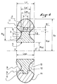
- the section of the wheel presented in section in Figure 1 is voluntarily schematized in order to clearly detach the features of the invention.
- the wheel consists of a hub 1 on which is fixed a tread 2.
- the hub 1 has a generally annular shape of axis of revolution OO '. he includes an interface area ensuring cohesion between the hub 1 and the tread 2, a central surface 4 substantially cylindrical intended to cooperate with means fixing the wheel on an OO 'axis rotation shaft (not shown) and a hub body joining the central surface to the interface area.
- the interface zone between the hub 1 and the tread 2 comprises an interface surface 5 of generally cylindrical shape and an interlock 6 of generally substantially annular shape extending radially from interface surface 5.
- the interlock 6 generally consists of a belt 11 connected to the interface surface by a plurality substantially radial uprights 12 (see fig. 5).
- a throat annular 3 the profile of which is embodied by a contour in dashed line in Figure 1, is provided on each of flanks of the wheel. According to the invention, the throat is radially limited on one side by the hub 1 and on the other by the tread 2.
- the wall 7 of the groove 3 breaks down therefore in a central part 8 which constitutes a portion of the lateral surface 13 of the hub body 1 and a part peripheral 9 which constitutes a portion of the surface outer 14 of the tread 2.
- the profile of this throat is characterized by the fact that the depth Lg of the groove is at least greater than 20% of the width Lsc of the central surface 4.
- the peripheral part 9 of the wall 7 of the groove 3 has a straight profile, while the central part 8 has a curved profile.
- the width of the interface surface 5 Lsi is between 20% and 80% of the width of the surface central Lsc, preferably between 40% and 60%.
- the general profile of the throat is a profile substantially triangular in which the profile of the central part has a appreciably rounded shape.
- the bottom 10 of the groove 3 is a circle whose center is on the axis OO '.
- the smallest width of the hub is at the bottom of the two annular grooves arranged on either side of the wheel. This width, noted Lm in Figure 1, is smaller than the width of the Lsi interface surface.
- the maximum width of the tread noted Lr in the figure, is substantially equal to the width of the central surface Lsc, which corresponds to the maximum width of the
- FIG. 2 shows a skate wheel whose hub 1 is monoblock and is traversed by cavities 15 of substantially shaped cylindrical.
- These rolling bearings (25) are of the type ball bearings and are two in number, arranged in both axial ends of the central surface of the hub.
- two shoulders are provided in the surface hub center. This arrangement of the bearings ensures that wheel increased stability, even when the skater is in the pushing phase and the wheel is stressed in a direction which is not contained in its median plane. Of them shoulders 16 separate the central surface 4 into three surfaces cylindrical.
- the peripheral part 9 of the wall 7 of the groove 3 has a straight profile, it does not include a sharp angle, while the central part 8 has a curved profile.
- the width Lsi of the interface surface 5 corresponds approximately to 50% of the width Lsc of the central surface 4.
- the use of a significantly stiffer material than those commonly used in hub manufacturing will make such a superfluous increase in the volume of the interlock 6.
- the bottom of each annular grooves is a circle located on the outer surface of the hub.
- the width of the wheel Lr is substantially equal to the width of the central surface of the hub Lsc. In fact she is significantly lower in a proportion such as: 0.8 Lsc ⁇ Lr ⁇ Lsc.
- the material used for the tread is a polyurethane elastomer with shore hardness included between 60 A and 85 A, while the hub is made of material plastic.
- Figure 3 shows a third embodiment of the invention in which the bottom 10 of each of the grooves 3 located on the side of the wheel is precisely at level of the interface surface 5.
- the wall 7 of the groove annular a on its portion coinciding with the surface outer 14 of the tread 2, an arcuate profile of circle.
- the lateral surface 13 of the hub 1 has, for its part, a profile consisting of two portions of an arc.
- the body of hub 1 has a geometry that recalls the structure of a wheel bicycle in the sense that the junction between the central surface 4 of the hub 1 and the interface zone is produced by means of lateral branches 17 arranged alternately on a blank, then on the other, of the wheel.
- an interlock 6 is provided whose height Ri is greater than its width Li.
- Figure 4 shows a fourth embodiment of the invention in which the tread 2 has a profile substantially circular.
- the lateral surface 13 of the hub is, meanwhile, consisting essentially of two flanges 18 substantially vertical.
- the profile of the groove 3 is therefore, in in this case, a portion of trapezium extended by a portion of arc of circle at the level of the tread 2.
- the width of the tread 2 is significantly lower than the width of the central surface 4 of the hub.
- the hub body consists entirely of non-through cavities 15 which open alternately on one side or the other of the wheel. Such a structure allows while minimizing the thickness of the walls separating the cavities 15 from each other to optimize the rigidity of the hub structure 1.
- the width Li of the interlock 6 is practically equal to the width Lsi.
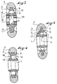
- Figures 5, 6 and 7 are respectively the front view, a view in radial section and a perspective of the hub 1 of a wheel according to a fifth embodiment of the invention.
- the hub body 1 is made up of six profiled arms 19.
- the interlock includes a belt 11 connected to the surface interface 5 by twelve uprights 12 having a lateral contour similar to that of branches 19. Preferably, some of these uprights 12 are located in the extension of the branches 19.
- the central surface 4 is designed to accommodate the two bearing rings with a diameter of 22 mm and a spacer (not shown).
- FIGS 8, 9 and 10 show respectively the front view, a radial section view and a perspective of the hub 1 of a wheel according to a sixth mode of realization of the invention.
- This hub 1 takes up a construction similar to that of the previous embodiment. Cavities 15 are arranged there and separated from each other by profiled branches 19. The bottom 10 of the groove is located on the lateral surface 13 of the hub 1.
- the central surface 4 is designed to receive bearing rings with a diameter of 16 mm.
- Figures 11, 12, and 13 respectively show the front view, a sectional view radial and a perspective of a complete wheel according the invention and using the hub 1 shown in Figures 8-10.
- the manufacture of a wheel according to the invention comprises many stages; manufacturing the hub, molding the tread and finish.
- the hub can be made various materials, including aluminum, polyamide, polyurethane, polybutylene terephthalate, polycarbonate or a magnesium or titanium alloy. This hub is achievable by molding, injection, gravity casting, extrusion or by stamping, forging or stamping.
- the hub is then placed in a lower mold 20, the centering being provided by a centering pin 24.
- the shape of the lower mold 20 corresponds exactly to the final form that we want to give to the tread; that is to say that the lower mold 20 differs from a classic mold by the presence of a rim annular 22 on which the peripheral surface of the hub 1.
- the upper mold 21 is then put in place.
- a molding chimney 23 comes to rest on the hub 1 defining an annular orifice through which we will be able pour or inject the tread material.
- demoulding we come to cut using a fine blade the "carrot" of molding in order to obtain the desired profile.
- the blade will not pose any particular problem.
- a cutting the carrot may be more difficult and more expensive to implement.
- We will then move towards a different technique of using a 25 punch having the imprint of the desired surface and the dimensions exterior of the pouring chimney. Directly after the pouring the tread material, introducing the punch in the pouring chimney, will eventually drive out the superfluous material and will give the tread the profile desired.
- the present invention is not limited to examples of previous embodiments which are presented in this presentation for information only.
- the advantages of the invention are independent of the configuration chosen for the hub, that is to say, the shape and number of cavities, the dimensions of the interlock, the materials used. They are also independent of the type and number of materials chosen for the tread.
Abstract
Description
L'invention concerne une roue pour patin à roulettes, notamment un patin dont les roues sont en lignes.The invention relates to a roller skate wheel, in particular a skate whose wheels are in lines.
Les roues de patin sont généralement constituées d'un moyeu fait d'une matière plastique très rigide, comme par exemple un polyamide, sur lequel on vient surmouler une bande de roulement faite d'un ou de plusieurs matériaux, présentant un module de traction plus faible que celui du moyeu, comme par exemple un polyuréthanne.The skate wheels generally consist of a hub made of a very rigid plastic, such as a polyamide, on which a tread is molded made of one or more materials, presenting a module of lower traction than that of the hub, such as a polyurethane.
Les caractéristiques que doit posséder une bonne roue sont multiples. Tout d'abord, la bande de roulement doit avoir de bonnes qualités d'adhérence, ceci étant particulièrement vrai pour les parties de celle-ci qui seront en contact avec le sol dans les courbes, c'est-à-dire lorsque la roue sera inclinée. L'adhérence de la bande de roulement dépend principalement des propriétés du matériau qui la constitue, c'est-à-dire de sa constitution chimique et de ses propriétés macromoléculaires.The characteristics that a good wheel must have are multiple. First, the tread should have good adhesion qualities, this being particularly true for the parts of it that will be in contact with the ground in curves, that is to say when the wheel is tilted. The tread grip mainly depends on the properties of the material from which it is made, i.e. chemical constitution and its macromolecular properties.
Deuxièmement, la roue ne doit pas être trop souple. En effet une trop grande souplesse de la roue entraíne une importante déformation de celle-ci, ce qui nuit aux performances, notamment en vitesse et stabilité.Second, the wheel should not be too soft. In effect too great flexibility of the wheel causes a significant deformation thereof, which harms performance, especially in speed and stability.
Troisièmement, la roue doit être la plus résiliante possible. La résilience d'une roue se traduit par sa capacité à restituer le maximum de l'énergie qui lui est transmise. Ceci s'apprécie facilement par l'effet de rebond de la roue. Une roue fortement résiliante favorise donc la vitesse car elle est capable de restituer une part importante de l'énergie lors de la détente qui suit la compression de la roue. Une roue peu résiliante va absorber beaucoup de cette énergie et la dissiper sous forme de chaleur.Third, the wheel must be the most resilient possible. The resilience of a wheel is reflected in its ability to restore the maximum of the energy transmitted to it. This easily appreciated by the rebound effect of the wheel. A highly resilient wheel therefore promotes speed because it is able to restore a significant part of the energy during the trigger that follows the compression of the wheel. A little wheel resilient will absorb a lot of this energy and dissipate it in the form of heat.
Quatrièmement, une roue de patin à roulette en ligne doit être telle qu'à aucun moment, lors de l'utilisation, le moyeu vienne en contact avec le sol. En effet, en courbe et à très grande vitesse, c'est-à-dire lorsque la roue est très inclinée, la zone du moyeu qui se trouve à l'interface avec la bande de roulement, c'est-à-dire la zone périphérique du moyeu, risque de venir au contact du sol. Il en résulte automatiquement une perte définitive d'adhérence. Fourth, an inline skate wheel must be such that at no time during use does the hub come in contact with the ground. Indeed, in curve and at very high speed, i.e. when the wheel is very inclined, the area of the hub which is at the interface with the strip of bearing, i.e. the peripheral area of the hub, risk to come into contact with the ground. This automatically results in a permanent loss of grip.
Cinquièment, l'ensemble roue, axe et châssis doit être stable et ne permettre aucune déformation, notamment lorsque la roue est sollicitée selon une direction qui n'est pas contenue dans son plan médian.Fifth, the wheel, axle and chassis assembly must be stable and allow no deformation, especially when the wheel is stressed in a direction which is not contained in its median plane.
Enfin, une roue doit être légère et surtout peu coûteuse à fabriquer.Finally, a wheel must be light and above all inexpensive to to manufacture.
Dans le document WO 96/20030 on propose de construire une roue de patin dont les zones latérales de la bande de roulement ont une dureté moindre que la zone centrale. Une telle roue reste lourde et surtout très coûteuse à fabriquer.In document WO 96/20030, it is proposed to construct a skate wheel including the lateral areas of the tread have a lower hardness than the central area. Such a wheel remains heavy and above all very expensive to manufacture.
Dans un autre document, US 5,924,705, on propose de modifier la déformabilité des zones latérales de la bande de roulement en ménageant des gorges annulaires sur les flancs de cette dernière. En fonction des dimensions données aux gorges, l'utilisation d'une telle roue générera un gain de poids. Cependant une telle solution ne peut s'appliquer à tout profil de roue. En effet, pour éviter une modification trop importante du comportement de la roue dans les courbes, ces gorges annulaires situées dans la bande de roulement ne peuvent pas déboucher dans une zone qui, lorsque la roue sera inclinée, viendra au contact avec le sol. C'est l'une des raisons pour lesquelles, on a choisi dans ce document un profil de roue particulier; à savoir une roue ayant une surface de roulement sensiblement plate encadrée par des flancs sensiblement verticaux. Ce profil particulier donne en ligne droite une surface de contact relativement importante, ce qui limite les performances en vitesse.In another document, US 5,924,705, it is proposed to modify the deformability of the lateral zones of the strip bearing by providing annular grooves on the sides of the latter. Depending on the dimensions given to the grooves, the use of such a wheel will generate weight savings. However, such a solution cannot be applied to all profiles. wheel. Indeed, to avoid an excessive modification of the behavior of the wheel in curves, these grooves annulars located in the tread cannot lead into an area which, when the wheel is tilted, will come into contact with the ground. This is one of the reasons for which, we chose in this document a wheel profile particular; namely a wheel having a rolling surface substantially flat framed by flanks substantially vertical. This particular profile gives a straight line relatively large contact surface, which limits the speed performance.
Dans un autre mode de réalisation décrit dans ce même document, on prévoit une roue pour patin dont la rigidité est modifiable par l'ajout de disques dans des cavités spécialement adaptées pour les recevoir. Les disques sont amovibles et fixés sur le moyeu par l'intermédiaire de vis. Le choix, qui est fait dans ce mode réalisation, de la polyvalence a conduit le concepteur à n'envisager qu'une forme particulière de cavité; à savoir une cavité peu profonde. Il faut en effet s'assurer que, au niveau des cavités, la largeur du moyeu résiduelle soit suffisamment importante pour permettre la mise en place des moyens de fixation des disques. D'autre part une telle roue se révèle peu économique à fabriquer car elle nécessite l'assemblage de différentes pièces, notamment par vissage.In another embodiment described in this same document, a skate wheel is provided whose rigidity is changeable by adding discs in specially cavities adapted to receive them. The disks are removable and fixed on the hub by means of screws. The choice, which is made in this embodiment, versatility has led the designer to consider only one particular form of cavity; at know a shallow cavity. We have to make sure that, at the cavities, the width of the residual hub is large enough to allow the placement of means for fixing the discs. On the other hand such a wheel is proves uneconomical to manufacture because it requires the assembly of different parts, in particular by screwing.
Le brevet US 5,938,214 se propose de réduire l'angle d'encombrement latéral de l'ensemble châssis/roue. Pour ce faire, deux solutions sont proposées.US Patent 5,938,214 proposes to reduce the angle lateral dimensions of the chassis / wheel assembly. For this do, two solutions are proposed.
Dans la première, on vient, sur un moyeu classique, c'est-à-dire un moyeu dont la largeur permet la disposition de deux bagues de roulement et d'une entretoise, surmouler une bande de roulement élargie. Une telle disposition permet de diminuer l'angle d'encombrement latéral du sous-ensemble châssis/roue.In the first, we come, on a conventional hub, that is to say a hub whose width allows the arrangement of two bearing rings and a spacer, overmold a strip of enlarged bearing. Such an arrangement makes it possible to reduce the lateral space angle of the chassis / wheel sub-assembly.
D'autre part, grâce à une telle disposition, le risque de contact du moyeu avec le sol est pratiquement écarté. En revanche, l'obligation d'élargir la bande de roulement entraíne une augmentation du poids des roues et donc du patin ce qui va à l'encontre d'une recherche de performance. De plus, une telle roue nécessite un châssis spécifique, c'est-à-dire un châssis comprenant une pluralité de paires de brides indépendantes servant à la fixation des axes des roues. La stabilité du châssis est diminuée du fait de l'indépendance des quatre paires de brides.On the other hand, thanks to such a provision, the risk of contact of the hub with the ground is practically spread. In however, the obligation to widen the tread results an increase in the weight of the wheels and therefore of the skate which will against a search for performance. In addition, such wheel requires a specific chassis, i.e. a chassis comprising a plurality of pairs of independent flanges used to fix the wheel axles. The stability of chassis is reduced due to the independence of the four pairs of flanges.
La deuxième solution utilise une bande de roulement ayant un profil classique qui est fixée à un moyeu qui ne comporte qu'un seul roulement. Dans cette solution, le gain de poids se fait au détriment de la stabilité du maintien de la roue sur son axe.The second solution uses a tread having a classic profile which is fixed to a hub which does not have only one bearing. In this solution, the weight gain is done at the expense of the stability of maintaining the wheel on its axis.
Le document US 5,655,784 décrit une roue pour patin prévue pour être fixée sur un axe par l'intermédiaire d'un seul roulement et qui est équipée d'un bandage dont la largeur est réduite par rapport à celle du moyeu. D'autre part la dureté du matériau utilisé pour le bandage est plus importante que 85 duromètre A. Elle est en fait comprise entre 60 et 85 duromètre D. Une telle dureté donne à la roue une très faible résilience et n'offrira au patineur utilisant cette roue très peu d'adhérence. D'autre part, la présence d'un seul roulement nécessite l'utilisation d'un roulement de très grand diamètre extérieur, et n'offrira pas au patin une stabilité optimale, notamment lorsque celui-ci est sollicité selon une direction qui n'est pas contenue dans le plan longitudinal du patin. Document US Pat. No. 5,655,784 describes a skate wheel provided to be fixed on an axis via a single bearing and which is fitted with a bandage whose width is reduced compared to that of the hub. On the other hand the hardness of the bandage material is more important than 85 durometer A. It is actually between 60 and 85 durometer D. Such hardness gives the wheel very low resilience and will offer the skater using this wheel very little grip. On the other hand, the presence of a single bearing requires the use of a very large diameter bearing exterior, and will not offer optimal stability to the skate, especially when it is requested in a direction which is not contained in the longitudinal plane of the skate.
Les roues standard couramment utilisées sur les patins à roulettes en ligne, ont un moyeu qui fait environ 24 mm de largeur et dont le diamètre extérieur oscille en général entre 38 et 45 mm. Il s'agit bien entendu du diamètre ne tenant pas compte de l'interlock qui lui est noyé dans la bande de roulement. Cette valeur est à rapporter au diamètre extérieur total d'une roue qui oscille approximativement entre 72 mm et 82 mm. On estime en effet que pour s'affranchir du risque d'un contact du moyeu avec le sol, le diamètre extérieur du moyeu ne doit pas dépasser 60% de la valeur du diamètre extérieur total de la roue, et de préférence ne doit pas dépasser 55%. Les roues qui disposent d'un moyeu plus large que 45 mm et dont le diamètre ne dépasse pas 82 mm font courir à l'utilisateur un risque important de contact moyeu/sol.The standard wheels commonly used on skates with casters in line, have a hub that is about 24mm in width and whose outside diameter generally oscillates between 38 and 45 mm. This is of course the diameter not holding account of the interlock that is drowned in the strip of rolling. This value should be related to the outside diameter total of a wheel which oscillates approximately between 72 mm and 82 mm. It is believed that to overcome the risk of contact of the hub with the ground, the outside diameter of the hub does not must not exceed 60% of the value of the total outside diameter of the wheel, and preferably should not exceed 55%. The wheels which have a hub wider than 45 mm and the diameter does not exceed 82 mm make the user run a significant risk of hub / ground contact.
Les roues standard sont d'autre part montées sur un axe par l'intermédiaire de deux paliers à roulements dont le diamètre est inférieur ou égal à 22 millimètres. Les deux roulements sont, disposés distants l'un de l'autre, aux deux extrémités de la surface intérieure du moyeu.The standard wheels are also mounted on an axle by by means of two rolling bearings whose diameter is less than or equal to 22 millimeters. The two bearings are, spaced apart from each other, at both ends of the inner surface of the hub.
Pour des raisons économiques, la fabrication de la plus grande partie des roues de patin fait appel aux techniques de surmoulage des matières plastiques. Le moyeu est d'abord obtenu par moulage ou par injection plastique, on vient ensuite surmouler la bande de roulement. On utilise alors le moulage par gravité le long d'une cheminée de moulage. Après démoulage il subsiste une carotte de moulage située sur l'un des flancs de la roue au niveau de l'interface moyeu bande de roulement. Cette carotte est alors découpée suivant une direction perpendiculaire à l'axe de la roue. L'obtention des roues de patin par surmoulage permet d'obtenir des roues présentant des performances satisfaisantes à un coût modéré. En revanche, elle ne permet pas d'obtenir des roues ayant un profil particulier, notamment à cause de la découpe de la carotte de moulage qui est perpendiculaire à l'axe de la roue.For economic reasons, the manufacture of the most large part of the skate wheels uses the techniques of overmolding of plastic materials. The hub is first obtained by molding or plastic injection, we come next overmold the tread. We then use the molding by gravity along a molding chimney. After demolding there remains a molding core located on one of the sides of the wheel at the hub tread interface. This carrot is then cut in a direction perpendicular to the axis of the wheel. Obtaining wheels skid by overmolding makes it possible to obtain wheels having satisfactory performance at moderate cost. However, it does not make it possible to obtain wheels having a particular profile, especially because of the cutting of the molding core which is perpendicular to the axis of the wheel.
La présente invention a pour but de remédier aux inconvénients précités. Il s'agit en l'occurrence de concevoir une roue bénéficiant d'une très bonne adhérence et ce même sous une forte inclinaison et qui permet un gain de poids. Il s'agit également de concevoir une roue qui même lorsqu'elle sera utilisée dans des configurations standards autorisera une augmentation du diamètre extérieur du moyeu, au sens défini ci-dessus. La présente invention consiste également en une méthode de fabrication permettant l'obtention d'une telle roue.The object of the present invention is to remedy the aforementioned drawbacks. This is about designing a wheel with very good grip, even under a strong inclination and which allows weight gain. It's about also to design a wheel which even when it is used in standard configurations will allow a increase in the outside diameter of the hub, in the sense defined above. The present invention also consists of a method manufacturing to obtain such a wheel.
Afin de résoudre le problème posé, on prévoit une roue comportant :
- une bande de roulement de forme générale annulaire d'axe de révolution 00',
- un moyeu de forme générale annulaire d'axe de révolution 00' comprenant une zone d'interface assurant la cohésion du moyeu et de la bande de roulement, une surface centrale sensiblement cylindrique destinée à coopérer avec des moyens fixant la roue sur un arbre de rotation d'axe 00' et un corps de moyeu joignant la surface centrale à la zone d'interface,
- une gorge annulaire d'axe de révolution 00' limitée radialement d'un côté par le corps du moyeu et de l'autre côté, au moins partiellement, par la bande de roulement, ladite gorge ayant un profil de forme sensiblement triangulaire, trapézoïdal, semi-circulaire ou de forme combinant des portions des trois profils précédents.
- a tread of generally annular shape with axis of revolution 00 ′,
- a hub of generally annular shape with an axis of revolution 00 ′ comprising an interface zone ensuring the cohesion of the hub and the tread, a substantially cylindrical central surface intended to cooperate with means fixing the wheel on a rotation shaft with axis 00 'and a hub body joining the central surface to the interface zone,
- an annular groove with an axis of revolution 00 ′ bounded radially on one side by the body of the hub and on the other side, at least partially, by the tread, said groove having a profile of substantially triangular, trapezoidal shape, semi-circular or shaped combining portions of the three previous profiles.
La gorge annulaire n'étant pas ménagée seulement dans la bande de roulement ou dans le moyeu mais dans les deux à la fois, on peut donc augmenter le volume évidé par la gorge et ainsi obtenir un gain de poids plus important par rapport aux roues connues dans l'état de la technique. De plus, du fait de sa largeur moindre, la surface d'interface moyeu/bande de roulement ne risque plus de venir au contact du sol lorsque la roue est inclinée. D'autre part, pour un diamètre de roue donné, on peut utiliser un moyeu de diamètre plus important. Compte tenu des différence de densité et de rigidité entre les matériaux couramment utilisés pour le moyeu et la bande de roulement, un gain de poids approchant 20% peut être obtenu grâce à la roue selon l'invention.The annular groove is not provided only in the tread or in the hub but in both at the times, we can therefore increase the volume hollowed out by the throat and thus gain greater weight gain compared to wheels known in the state of the art. In addition, due to its smaller width, the hub / strip interface surface bearing is no longer likely to come into contact with the ground when the wheel is tilted. On the other hand, for a wheel diameter given, one can use a larger diameter hub. Given the difference in density and rigidity between the commonly used materials for the hub and strip bearing, a weight gain approaching 20% can be obtained thanks to the wheel according to the invention.
Le fond de la gorge annulaire, c'est-à-dire l'ensemble des points de plus grande profondeur, est naturellement un cercle dont le centre est situé sur l'axe OO'. Celui-ci se trouve sur la surface latérale du moyeu, distant de la surface d'interface moyeu/bande de roulement. Dans un mode de réalisation préférentiel de l'invention, la profondeur de la gorge est au moins supérieure à 20% de sa largeur. Avantageusement, une gorge annulaire est prévue sur chacun des flancs, ces deux gorges ayant une position symétrique l'une de l'autre par rapport au plan médian de la roue. Le fond de ces deux gorges annulaires correspond à l'endroit où le moyeu a sa plus faible largeur. De préférence, cette plus petite largeur du moyeu Lm est inférieure à la largeur de la bande de roulement au niveau de l'interface bande de roulement / moyeu appelée encore largeur de la surface d'interface Lsi.The bottom of the annular groove, i.e. all of the points of greatest depth, is naturally a circle whose center is located on the axis OO '. This is on the lateral surface of the hub, distant from the interface surface hub / tread. In one embodiment preferred of the invention, the depth of the groove is at less than 20% of its width. Advantageously, a annular groove is provided on each side, these two grooves having a position symmetrical to each other by in relation to the median plane of the wheel. The bottom of these two gorges annular corresponds to where the hub has its weakest width. Preferably, this smaller width of the hub Lm is less than the width of the tread at level of the tread / hub interface also called width of the interface surface Lsi.
De préférence, la bande de roulement comprend un matériau dont la dureté est comprise entre 60 et 90 shore A.Preferably, the tread comprises a material whose hardness is between 60 and 90 shore A.
De préférence, la limite centrale de la gorge annulaire se trouve au voisinage de la surface centrale du moyeu. En d'autres termes, on dira que, radialement, la gorge annulaire commence au voisinage de la surface centrale du moyeu.Preferably, the central limit of the annular groove is located near the central surface of the hub. In in other words, it will be said that, radially, the annular groove begins near the center surface of the hub.
La limite périphérique de la gorge se situe sur la bande de roulement. Dans un mode de réalisation préférentiel cette limite périphérique correspond avec la limite centrale de la surface de la bande de roulement qui est susceptible de venir au contact du sol. De préférence cette limite périphérique est positionnée de telle façon que la différence entre le rayon de roue et le rayon de la limite périphérique de la gorge est sensiblement égal à la moitié de la largeur de la roue prise au niveau de la bande de roulement.The peripheral limit of the throat is located on the band of rolling. In a preferred embodiment this peripheral limit corresponds with the central limit of the tread surface that is likely to come in contact with the ground. Preferably this peripheral limit is positioned so that the difference between the radius of wheel and the radius of the peripheral limit of the groove is substantially equal to half the width of the wheel taken at tread level.
Avantageusement, le corps de moyeu n'est pas plein mais ajouré par des cavités qui peuvent être ou non traversantes. Pour des raisons de simplicité, on continuera dans la suite de l'exposé et dans les revendications à appeler surface latérale du moyeu, la surface constituant le contour latéral extérieur du moyeu, c'est-à-dire sans tenir compte de la présence ou non de cavités ménagées dans le corps du moyeu.Advantageously, the hub body is not full but perforated by cavities which may or may not be through. For reasons of simplicity, we will continue in the following the description and in the claims to be called lateral surface of the hub, the surface constituting the external lateral contour of the hub, that is to say without taking into account the presence or not cavities in the body of the hub.
La gorge étant limitée radialement, d'un côté par le moyeu et de l'autre par la bande de roulement, la surface de la gorge comprend une partie centrale constituant une portion de la surface latérale du corps du moyeu et une partie périphérique constituant une portion de la surface extérieure de la bande de roulement. Comme pour la surface latérale du moyeu, que celui-ci soit ou non ajouré par des cavités, on parlera de partie centrale de la surface de la gorge. La partie centrale de la paroi de la gorge comme sa partie périphérique peuvent avoir des profils différents. Cependant, on donnera de préférence à la partie périphérique le profil d'une portion de droite tandis que la partie centrale aura un profil courbe.The groove being limited radially, on one side by the hub and on the other by the tread, the surface of the groove includes a central part constituting a portion of the lateral surface of the hub body and a peripheral part constituting a portion of the outer surface of the strip of rolling. As for the lateral surface of the hub, let it whether or not perforated by cavities, we will speak of part center of the throat surface. The central part of the throat wall as its peripheral part can have different profiles. However, preference will be given to the peripheral part the profile of a straight portion while that the central part will have a curved profile.
Afin de résoudre le problème posé, on prévoit également une roue pour patin à roulettes constituée d'une bande de roulement et d'un moyeu, ledit moyeu comprenant une zone d'interface assurant la cohésion du moyeu et de la bande de roulement, une surface centrale sensiblement cylindrique destinée à coopérer avec des moyens fixant la roue sur un arbre de rotation et un corps de moyeu joignant la surface intérieure à la zone d'interface, ladite zone d'interface comprenant une surface d'interface sensiblement cylindrique sur laquelle repose la bande de roulement, la largeur de la surface d'interface est plus petite que 90% de la largeur de la surface centrale. Dans un mode de réalisation préférentiel, on donnera à la surface d'interface une largeur plus petite que 80% de la largeur de la surface centrale.In order to resolve the problem posed, provision is also made for roller skate wheel consisting of a tread and a hub, said hub comprising an interface zone ensuring the cohesion of the hub and the tread, a substantially cylindrical central surface intended to cooperate with means fixing the wheel on a rotation shaft and a hub body joining the inner surface to the area interface, said interface zone comprising a surface substantially cylindrical interface on which the tread, the width of the interface surface is less than 90% of the width of the central surface. In a preferred embodiment, we will give the surface interface width less than 80% of the width of the central surface.
De préférence, le matériau de la bande de roulement est un élastomère de polyuréthane défini par les caractéristiques intrasèques suivantes : un module élastique E' compris entre 6 et 11,3 et un module visqueux inférieur E'' à 0,25. D'autre part pour des raisons de confort, il est préféré d'utiliser pour la fabrication de la bande de roulement des matériaux dont la dureté shore A n'excède pas 85 A. Pour empêcher une usure trop rapide et conserver une bonne résilience à la roue, on choisira des matériaux dont la dureté est supérieure à 60 shore A.Preferably, the tread material is a polyurethane elastomer defined by the characteristics following intrasecs: an elastic modulus E 'between 6 and 11.3 and a viscous module lower E '' to 0.25. Else apart for reasons of comfort, it is preferred to use for the manufacture of the tread of materials including Shore A hardness does not exceed 85 A. To prevent wear too fast and maintain good resilience to the wheel, will choose materials whose hardness is greater than 60 shore AT.
De plus, pour fabriquer une roue selon l'invention on prévoit une méthode qui comprend les étapes suivantes :
- réalisation du moyeu par moulage, injection, coulée gravité, extrusion, estampage, forgeage ou matriçage ;
- disposition du moyeu dans un moule inférieur, dont la forme correspond exactement à la forme finale que l'on veut donner à une première moitié de la bande de roulement ;
- fermeture du moule par le positionnement d'un moule supérieur 21, dont la forme correspond essentiellement à la forme finale que l'on veut donner la seconde moitié de la bande de roulement moins la ou les zones correspondantes à la ou aux carottes de moulage, le plan de joint étant perpendiculaire à l'axe de la roue à fabriquer ;
- coulage par gravité du matériau de la bande de roulement
à l'aide d'une cheminée de moulage ;
ladite méthode comprenant, en outre, l'étape consistant à ; - découper la carotte de moulage suivant au moins une direction qui n'est pas parallèle au plan de joint.
- realization of the hub by molding, injection, gravity casting, extrusion, stamping, forging or stamping;
- arrangement of the hub in a lower mold, the shape of which corresponds exactly to the final shape which one wishes to give to a first half of the tread;
- closing the mold by positioning an
upper mold 21, the shape of which corresponds essentially to the final shape which one wishes to give the second half of the tread minus the area or areas corresponding to the molding core (s), the joint plane being perpendicular to the axis of the wheel to be manufactured; - gravity pouring of the tread material using a molding chimney;
said method further comprising the step of; - cut the molding core in at least one direction which is not parallel to the joint plane.
La découpe, non parallèle au plan de joint, de la carotte de moulage permet de fabriquer par la méthode de moulage par gravité des roues ayant un profil complexe.The cutting, not parallel to the joint plane, of the carrot molding allows to manufacture by the molding method by gravity of wheels with a complex profile.
L'invention sera mieux comprise et d'autres caractéristiques de celle-ci seront mises en évidence à l'aide de la description qui suit en référence au dessin schématique annexé qui illustre, à titre d'exemple non limitatif, plusieurs modes de réalisation et dans lequel :
- la figure 1 est une vue en coupe d'une roue selon un premier mode de réalisation,
- la figure 2 est une vue en coupe d'une roue selon un deuxième mode de réalisation,
- la figure 3 est une vue en coupe d'une roue selon un troisième mode de réalisation,
- la figure 4 est une vue en coupe d'une roue selon un quatrième mode de réalisation,
- les figures 5, 6 et 7 sont respectivement la vue de face, une vue en coupe radiale et une perspective du moyeu d'une roue selon un cinquième mode de réalisation de l'invention,
- les figures 8, 9 et 10 sont respectivement la vue de face, une vue en coupe radiale et une perspective du moyeu d'une roue selon un sixième mode de réalisation,
- les figures 11, 12, et 13 sont respectivement la vue de face, une vue en coupe radiale et une perspective d'une roue complète selon l'invention et utilisant le moyeu montré aux figures 8-10,
- la figure 14 est une vue en coupe éclatée des différentes pièce entrant avant la phase de moulage de la bande de roulement sur le moyeu,
- la figure 15 est une vue en coupe des mêmes pièces après coulage du matériau de la bande roulement.
- FIG. 1 is a sectional view of a wheel according to a first embodiment,
- FIG. 2 is a sectional view of a wheel according to a second embodiment,
- FIG. 3 is a sectional view of a wheel according to a third embodiment,
- FIG. 4 is a sectional view of a wheel according to a fourth embodiment,
- FIGS. 5, 6 and 7 are respectively the front view, a view in radial section and a perspective of the hub of a wheel according to a fifth embodiment of the invention,
- FIGS. 8, 9 and 10 are respectively the front view, a view in radial section and a perspective of the hub of a wheel according to a sixth embodiment,
- FIGS. 11, 12 and 13 are respectively the front view, a view in radial section and a perspective of a complete wheel according to the invention and using the hub shown in FIGS. 8-10,
- FIG. 14 is an exploded section view of the various parts entering before the tread molding phase on the hub,
- Figure 15 is a sectional view of the same parts after casting of the tread material.
La section de la roue présentée en section à la figure 1
est volontairement schématisée afin de détacher clairement les
caractéristiques de l'invention. La roue est constituée d'un
moyeu 1 sur lequel est fixée une bande de roulement 2. Le moyeu
1 a une forme générale annulaire d'axe de révolution OO'. Il
comprend une zone d'interface assurant la cohésion entre le
moyeu 1 et la bande de roulement 2, une surface centrale 4
sensiblement cylindrique destinée à coopérer avec des moyens
fixant la roue sur un arbre de rotation d'axe OO' (non
représentés) et un corps de moyeu joignant la surface centrale
à la zone d'interface. La zone d'interface entre le moyeu 1 et
la bande de roulement 2 comprend une surface d'interface 5 de
forme générale sensiblement cylindrique et un interlock 6 de
forme générale sensiblement annulaire s'étendant radialement
depuis la surface d'interface 5. Pour des raisons de poids, et
pour accroítre la superficie de contact moyeu/bande de
roulement, l'interlock 6 est en général constitué par une
ceinture 11 reliée à la surface d'interface par une pluralité
de montants 12 sensiblement radiaux (cf. fig.5). Une gorge
annulaire 3, dont le profil est matérialisé par un contour en
trait pointillé à la figure 1, est ménagée sur chacun des
flancs de la roue. Conformément à l'invention, la gorge est
limitée radialement d'un côté par le moyeu 1 et de l'autre par
la bande de roulement 2. La paroi 7 de la gorge 3 se décompose
donc en une partie centrale 8 qui constitue une portion de la
surface latérale 13 du corps du moyeu 1 et une partie
périphérique 9 qui constitue une portion de la surface
extérieure 14 de la bande de roulement 2. Le profil de cette
gorge se caractérise par le fait que la profondeur Lg de la
gorge est au moins supérieure à 20% de la largeur Lsc de la
surface centrale 4. La partie périphérique 9 de la paroi 7 de
la gorge 3 a un profil droit, tandis que la partie centrale 8 a
un profil courbe. La largeur de la surface d'interface 5 Lsi
est comprise entre 20% et 80% de la largeur de la surface
centrale Lsc, de préférence entre 40% et 60%. D'autre part, le
profil général de la gorge est un profil sensiblement
triangulaire dans lequel le profil de la partie centrale a une
forme sensiblement arrondie. Le fond 10 de la gorge 3 est un
cercle dont le centre est sur l'axe OO'. La plus petite largeur
du moyeu se trouve au niveau du fond des deux gorges annulaires
disposées de part et d'autre de la roue. Cette largeur, notée
Lm sur la figure 1, est plus petite que la largeur de la
surface d'interface Lsi. En revanche, la largeur maximale de la
bande de roulement, notée Lr sur la figure, est sensiblement
égale à la largeur de la surface centrale Lsc, qui correspond à
la largeur maximale du moyeu.The section of the wheel presented in section in Figure 1
is voluntarily schematized in order to clearly detach the
features of the invention. The wheel consists of a
La figure 2 montre une roue de patin dont le moyeu 1 est
monobloc et est traversé de cavités 15 de forme sensiblement
cylindrique. Ces paliers à roulement (25) sont de type
roulement à billes et sont au nombre de deux, disposés aux deux
extrémités axiales de la surface centrale du moyeu. De plus
pour assurer la butée des bagues extérieures des paliers à
roulements (25), deux épaulements sont ménagés dans la surface
centrale du moyeu. Cette disposition des roulements assure à la
roue une stabilité accrue, et ce même lorsque le patineur est
en phase de poussée et que la roue est sollicitée selon une
direction qui n'est pas contenue dans son plan médian. Deux
épaulements 16 séparent la surface centrale 4 en trois surfaces
cylindriques. La partie périphérique 9 de la paroi 7 de la
gorge 3 a un profil droit, il ne comprend pas d'angle vif,
tandis que la partie centrale 8 a un profil courbe. La largeur
Lsi de la surface d'interface 5 correspond approximativement à
50% de la largeur Lsc de la surface centrale 4. Pour éviter les
problèmes générés par l'amincissement du moyeu et la présence
de cavités, tels que le voilage de la roue ou l'affaiblissement
de celle-ci, on augmente le volume de l'interlock 6. De
préférence on donnera à l'interlock une largeur Li supérieure à
40% de la valeur de la largeur Lsi de la surface d'interface 5.
On pourra également augmenter le volume de l'interlock 6 en
augmentant sa hauteur Ri. En revanche, l'utilisation d'un
matériau sensiblement plus rigide que ceux couramment employés
dans la fabrication de moyeu rendra superflue une telle
augmentation du volume de l'interlock 6. Le fond de chacune des
gorges annulaires est un cercle situé sur la surface externe du
moyeu. La largeur de la roue Lr est sensiblement égale à la
largeur de la surface centrale du moyeu Lsc. En fait elle est
sensiblement inférieure dans une proportion telle que : 0,8 Lsc
< Lr < Lsc. FIG. 2 shows a skate wheel whose
Le matériau utilisé pour la bande de roulement est un élastomère de polyuréthane dont la dureté shore est comprise entre 60 A et 85 A, tandis que le moyeu est fait en matière plastique.The material used for the tread is a polyurethane elastomer with shore hardness included between 60 A and 85 A, while the hub is made of material plastic.
La figure 3 montre un troisième mode de réalisation de
l'invention dans lequel le fond 10 de chacune des gorges 3
ménagées sur les flancs de la roue se trouve précisément au
niveau de la surface d'interface 5. La paroi 7 de la gorge
annulaire a, sur sa portion coïncidant avec la surface
extérieure 14 de la bande de roulement 2, un profil en arc de
cercle. La surface latérale 13 du moyeu 1 a, quant à elle, un
profil constitué de deux portions d'arc de cercle. Le corps de
moyeu 1 a une géométrie qui rappelle la structure d'une roue de
bicyclette en ce sens que la jonction entre la surface centrale
4 du moyeu 1 et la zone d'interface est réalisée grâce à des
branches latérales 17 disposées alternativement sur un flan,
puis sur l'autre, de la roue. Pour améliorer la rigidité
latérale et augmenter son inertie, on prévoit un interlock 6
dont la hauteur Ri est plus importante que sa largeur Li.Figure 3 shows a third embodiment of
the invention in which the bottom 10 of each of the
La figure 4 montre un quatrième mode de réalisation de
l'invention dans lequel la bande de roulement 2 a un profil
sensiblement circulaire. La surface latérale 13 du moyeu est,
quant à elle, constituée essentiellement de deux flasques 18
sensiblement verticales. Le profil de la gorge 3 est donc, dans
ce cas, une portion de trapèze prolongée par une portion d'arc
de cercle au niveau de la bande de roulement 2 . La largeur de
la bande de roulement 2 est sensiblement inférieure à la
largeur de la surface centrale 4 du moyeu. Le corps du moyeu
est entièrement constitué de cavités 15 non traversantes qui
débouchent alternativement d'un côté ou de l'autre de la roue.
Une telle structure permet tout en minimisant l'épaisseur des
parois séparant les cavités 15 les unes des autres d'optimiser
la rigidité de la structure du moyeu 1. La largeur Li de
l'interlock 6 est pratiquement égale à la largeur Lsi.Figure 4 shows a fourth embodiment of
the invention in which the
Les figures 5, 6 et 7 sont respectivement la vue de face,
une vue en coupe radiale et une perspective du moyeu 1 d'une
roue selon un cinquième mode de réalisation de l'invention. Le
corps de moyeu 1 y est constitué de six branches profilées 19.
L'interlock comprend une ceinture 11 reliée à la surface
d'interface 5 par douze montants 12 ayant un contour latéral
similaire à celui des branches 19. De préférence, certains de
ces montants 12 se trouvent dans le prolongement des branches
19. La surface centrale 4 est prévue pour accueillir les deux
bagues de roulement d'un diamètre de 22 mm ainsi qu'une
entretoise (non représentée).Figures 5, 6 and 7 are respectively the front view,
a view in radial section and a perspective of the
Les avantages apportés par l'invention sont bien évidemment
indépendants du type et des dimensions des bagues de roulements
utilisées pour le montage de la roue selon l'invention sur un
axe. L'adoption de roulements d'un plus petit diamètre, comme
par exemple un roulement de diamètre 16 mm générera un gain de
poids plus important. Les figures 8, 9 et 10 montrent
respectivement la vue de face, une vue en coupe radiale et une
perspective du moyeu 1 d'une roue selon un sixième mode de
réalisation de l'invention. Ce moyeu 1 reprend une construction
similaire à celle du mode de réalisation précédent. Des cavités
15 y sont ménagées et séparées les unes des autres par des
branches profilées 19. Le fond 10 de la gorge se situe sur la
surface latérale 13 du moyeu 1. La surface centrale 4 est
prévue pour recevoir des bagues de roulement de diamètre 16 mm.
Etant donné que la limite centrale de la gorge annulaire se
situe directement au voisinage de la surface centrale 4 du
moyeu 1, l'utilisation de roulements d'un diamètre extérieur
plus petit permet d'augmenter la largeur Rg de la gorge 3 et
par conséquent, le gain de poids. Les figures 11, 12, et 13
montrent respectivement la vue de face, une vue en coupe
radiale et une perspective d'une roue complète selon
l'invention et utilisant le moyeu 1 montré aux figures 8-10.The advantages brought by the invention are obviously
independent of the type and size of bearing rings
used for mounting the wheel according to the invention on a
axis. The adoption of smaller diameter bearings, such as
for example a bearing with a diameter of 16 mm will generate a gain of
greater weight. Figures 8, 9 and 10 show
respectively the front view, a radial section view and a
perspective of the
La fabrication d'une roue selon l'invention comprend
plusieurs étapes; la fabrication du moyeu, le moulage de la
bande de roulement et la finition. Le moyeu peut être réalisé
en divers matériaux, notamment l'aluminium, un polyamide, un
polyuréthanne, un polybutylène téréphtalate, un polycarbonate
ou un alliage de magnésium ou de titane. Ce moyeu est
réalisable par moulage, par injection, coulée gravité,
extrusion ou par estampage, forgeage ou matriçage. Le moyeu est
ensuite placé dans un moule inférieur 20, le centrage étant
assuré par un pion de centrage 24. La forme du moule inférieur
20 correspond exactement à la forme finale que l'on veut donner
à la bande de roulement; c'est-à-dire que le moule inférieur 20
se distingue d'un moule classique par la présence d'un rebord
annulaire 22 sur lequel s'appuie la surface périphérique du
moyeu 1. Le moule supérieur 21 est alors mis en place. Une
cheminée de moulage 23 vient prendre appui sur le moyeu 1
définissant un orifice annulaire par lequel on va pouvoir
couler ou injecter le matériau de la bande de roulement. Après
démoulage, on vient découper à l'aide d'une fine lame la
"carotte" de moulage afin d'obtenir le profil désiré. Dans le
cas où le profil de la portion de la gorge qui coïncide avec la
bande de roulement ne comprend pas d'angle vif, une découpe à
la lame ne posera pas de problème particulier. Dans le cas
contraire ou dans le cas où ce profil est plus complexe, une
découpe de la carotte pourra s'avérer plus difficile et plus
onéreuse à mettre en oeuvre. On s'orientera alors vers une
technique différente qui consiste à utiliser un poinçon 25
ayant l'empreinte de la surface désirée et les dimensions
extérieures de la cheminée de coulée. Directement après la
coulée du matériau de la bande de roulement, l'introduction du
poinçon dans la cheminée de coulée, chassera éventuellement la
matière superflue et donnera à la bande de roulement le profil
voulu.The manufacture of a wheel according to the invention comprises
many stages; manufacturing the hub, molding the
tread and finish. The hub can be made
various materials, including aluminum, polyamide,
polyurethane, polybutylene terephthalate, polycarbonate
or a magnesium or titanium alloy. This hub is
achievable by molding, injection, gravity casting,
extrusion or by stamping, forging or stamping. The hub is
then placed in a
Bien entendu, la présente invention ne se limite pas aux exemples de mode de réalisation précédents qui sont présentés dans cet exposé à titre purement indicatif. Par exemple, il est clair que les avantages apportés par l'invention sont indépendants de la configuration choisie pour le moyeu, c'est-à-dire, la forme et le nombre des cavités, les dimensions de l'interlock, les matériaux utilisés. Ils sont également indépendant du type et du nombre des matériaux choisis pour la bande de roulement. Of course, the present invention is not limited to examples of previous embodiments which are presented in this presentation for information only. For example, it is clear that the advantages of the invention are independent of the configuration chosen for the hub, that is to say, the shape and number of cavities, the dimensions of the interlock, the materials used. They are also independent of the type and number of materials chosen for the tread.
- 1-1-
- MoyeuHub
- 2-2-
- Bande de roulementTread
- 3-3-
- Gorge annulaireRing throat
- 4-4-
- Surface centraleCentral surface
- 5-5-
- Surface d'interfaceInterface surface
- 6-6-
- InterlockInterlock
- 7-7-
- ParoiWall
- 8-8-
- Partie centraleCentral part
- 9-9-
- Partie périphériquePeripheral part
- 10-10-
- FondBackground
- 11-11-
- Ceinture (de l'interlock)Belt (of interlock)
- 12-12-
- Montant (de l'interlock)Amount (of interlock)
- 13-13-
- Surface latérale (du corps de moyeu)Lateral surface (of the hub body)
- 14-14-
- Surface extérieure (de la bande de roulement)Outer surface (of the tread)
- 15-15-
- CavitésCavities
- 16-16-
- EpaulementShoulder
- 17-17-
- Branches latéralesSide branches
- 18-18-
- FlasqueFlaccid
- 19-19-
- Branche profiléeProfiled branch
- 20-20-
- Moule inférieurBottom mold
- 21-21-
- Moule supérieurUpper mold
- 22-22-
- Rebord annulaireAnnular rim
- 23-23-
- Cheminée de moulageMolding chimney
- 24-24-
- Pion de centrageCentering pin
- 25-25-
- Palier à roulementsRolling bearing
Claims (13)
ladite roue étant, en outre, caractérisée en ce que :
said wheel being, furthermore, characterized in that:
ladite roue étant, en outre, caractérisée en ce que :
said wheel being, furthermore, characterized in that:
ladite méthode comprenant, en outre, l'étape consistant à ;
said method further comprising the step of;
Applications Claiming Priority (2)
| Application Number | Priority Date | Filing Date | Title |
|---|---|---|---|
| FR9913965 | 1999-11-02 | ||
| FR9913965A FR2800295B1 (en) | 1999-11-02 | 1999-11-02 | SKATE WHEEL |
Publications (1)
| Publication Number | Publication Date |
|---|---|
| EP1097734A1 true EP1097734A1 (en) | 2001-05-09 |
Family
ID=9551826
Family Applications (1)
| Application Number | Title | Priority Date | Filing Date |
|---|---|---|---|
| EP00123220A Withdrawn EP1097734A1 (en) | 1999-11-02 | 2000-10-26 | Roller-skate wheel |
Country Status (3)
| Country | Link |
|---|---|
| US (1) | US6629735B1 (en) |
| EP (1) | EP1097734A1 (en) |
| FR (1) | FR2800295B1 (en) |
Cited By (3)
| Publication number | Priority date | Publication date | Assignee | Title |
|---|---|---|---|---|
| WO2002094121A1 (en) * | 2001-05-24 | 2002-11-28 | Benetton Group S.P.A. | A method for manufacturing a wheel and a wheel obtained thereby |
| WO2002094395A1 (en) * | 2001-05-24 | 2002-11-28 | Benetton Group, S.P.A. | A wheel, particularly for skates. rollers and the like |
| EP2589501A1 (en) * | 2011-11-07 | 2013-05-08 | Dijiya Energy Saving Technology Inc. | Solid wheel |
Families Citing this family (18)
| Publication number | Priority date | Publication date | Assignee | Title |
|---|---|---|---|---|
| US7418988B2 (en) * | 1999-12-10 | 2008-09-02 | Michelin Recherche Et Technique S.A. | Non-pneumatic tire |
| US6752471B2 (en) * | 2002-05-13 | 2004-06-22 | Ben M. Hsia | Stroller wheel structure |
| WO2004020267A2 (en) * | 2002-08-30 | 2004-03-11 | Aethon, Inc. | Robotic cart pulling vehicle |
| FR2844260B1 (en) * | 2002-09-09 | 2004-11-12 | Cit Alcatel | ANTI-PMD SYSTEM |
| CA2465749A1 (en) * | 2004-04-01 | 2005-10-01 | Societe Manufacturiere Ro-Ma Inc. | Wheel structure |
| US20050269866A1 (en) * | 2004-06-03 | 2005-12-08 | Mcgoon Doug Iv | Multi-piece wheel assembly with transparent components |
| US7125083B2 (en) * | 2004-06-04 | 2006-10-24 | Nhs, Inc. | Wheel with dual density |
| WO2007047510A2 (en) | 2005-10-14 | 2007-04-26 | Aethon, Inc. | Robotic inventory management |
| US20100031508A1 (en) * | 2006-04-07 | 2010-02-11 | Peio Todorov Stoyanov | One-piece wheel produced by casting a wheel hub and spin-forming rims |
| US20080246330A1 (en) * | 2007-04-09 | 2008-10-09 | Mearthane Products Corporation | In-line Skates, Skate Wheels and Wheel Hubs |
| CN103608740B (en) | 2011-04-11 | 2017-06-30 | 克朗设备公司 | The method and apparatus that multiple automatic incomplete vehicles are effectively dispatched using coordinated path planner |
| US20140058634A1 (en) | 2012-08-24 | 2014-02-27 | Crown Equipment Limited | Method and apparatus for using unique landmarks to locate industrial vehicles at start-up |
| US20150042147A1 (en) * | 2013-08-09 | 2015-02-12 | Collin Gabriel SNOEK | Wheel |
| USD783752S1 (en) * | 2013-08-09 | 2017-04-11 | Capsule Collective L.L.C. | Wheel |
| US9162527B1 (en) * | 2014-07-14 | 2015-10-20 | White Oak Industries, Inc. | Mechanically interlocked wheel |
| US9914500B2 (en) * | 2015-07-01 | 2018-03-13 | GM Global Technology Operations LLC | Kickscooter with detachable electric drive module with hub-center steering and vibration dampening wheel |
| US10182629B2 (en) * | 2015-10-30 | 2019-01-22 | Milwaukee Electric Tool Corporation | Wheeled device and wheel assembly |
| FR3095447B1 (en) | 2019-04-26 | 2021-12-24 | Michelin & Cie | MANUALLY TRANSPORTABLE VEHICLE WHEEL TIRE |
Citations (7)
| Publication number | Priority date | Publication date | Assignee | Title |
|---|---|---|---|---|
| US5312844A (en) * | 1993-05-14 | 1994-05-17 | S&W Plastics, Inc. | Method of producing polyurethane injection molded in-line skate wheels |
| WO1996020030A1 (en) | 1994-12-23 | 1996-07-04 | Alfaplastic S.R.L. | A wheel having different hardnesses for roller skates presenting aligned wheels |
| WO1997018937A1 (en) * | 1995-11-17 | 1997-05-29 | Vanio Tessaro | Method for producing skate rollers, mould for manufacturing the same and skate roller manufactured by said method and/or in said mould |
| US5655784A (en) | 1995-03-27 | 1997-08-12 | Lee; Charles J. | High performance in-line roller skate wheels |
| WO1998004423A1 (en) * | 1996-07-12 | 1998-02-05 | The Hyper Corporation | Hollow core pneumatic wheel having contour conforming polyurethane wall |
| US5924705A (en) | 1995-11-03 | 1999-07-20 | Mrk Handels-Ag | Single-track roller skate and wheels for use therewith |
| US5938214A (en) | 1996-05-30 | 1999-08-17 | Nordica S.P.A. | Skate with in-line wheels |
Family Cites Families (5)
| Publication number | Priority date | Publication date | Assignee | Title |
|---|---|---|---|---|
| IT1266132B1 (en) * | 1993-09-10 | 1996-12-20 | Nordica Spa | WHEEL STRUCTURE, PARTICULARLY FOR SKATES OR SKATEBOARDS |
| US5641365A (en) * | 1994-12-12 | 1997-06-24 | The Hyper Corporation | Pre-pressurized in-line skate wheel |
| US5655785A (en) | 1995-03-27 | 1997-08-12 | Lee; Charles J. | High performance in-line roller skate wheels |
| US6227622B1 (en) * | 1997-06-20 | 2001-05-08 | K-2 Corporation | Multilayer skate wheel |
| USD433088S (en) | 1999-03-19 | 2000-10-31 | Salomon S.A. | Skate wheel |
-
1999
- 1999-11-02 FR FR9913965A patent/FR2800295B1/en not_active Expired - Fee Related
-
2000
- 2000-10-26 EP EP00123220A patent/EP1097734A1/en not_active Withdrawn
- 2000-11-01 US US09/702,890 patent/US6629735B1/en not_active Expired - Fee Related
Patent Citations (8)
| Publication number | Priority date | Publication date | Assignee | Title |
|---|---|---|---|---|
| US5312844A (en) * | 1993-05-14 | 1994-05-17 | S&W Plastics, Inc. | Method of producing polyurethane injection molded in-line skate wheels |
| US5908519A (en) * | 1994-12-12 | 1999-06-01 | The Hyper Corporation | Hollow core in-line skate wheel having contour conforming polyurethane wall |
| WO1996020030A1 (en) | 1994-12-23 | 1996-07-04 | Alfaplastic S.R.L. | A wheel having different hardnesses for roller skates presenting aligned wheels |
| US5655784A (en) | 1995-03-27 | 1997-08-12 | Lee; Charles J. | High performance in-line roller skate wheels |
| US5924705A (en) | 1995-11-03 | 1999-07-20 | Mrk Handels-Ag | Single-track roller skate and wheels for use therewith |
| WO1997018937A1 (en) * | 1995-11-17 | 1997-05-29 | Vanio Tessaro | Method for producing skate rollers, mould for manufacturing the same and skate roller manufactured by said method and/or in said mould |
| US5938214A (en) | 1996-05-30 | 1999-08-17 | Nordica S.P.A. | Skate with in-line wheels |
| WO1998004423A1 (en) * | 1996-07-12 | 1998-02-05 | The Hyper Corporation | Hollow core pneumatic wheel having contour conforming polyurethane wall |
Cited By (3)
| Publication number | Priority date | Publication date | Assignee | Title |
|---|---|---|---|---|
| WO2002094121A1 (en) * | 2001-05-24 | 2002-11-28 | Benetton Group S.P.A. | A method for manufacturing a wheel and a wheel obtained thereby |
| WO2002094395A1 (en) * | 2001-05-24 | 2002-11-28 | Benetton Group, S.P.A. | A wheel, particularly for skates. rollers and the like |
| EP2589501A1 (en) * | 2011-11-07 | 2013-05-08 | Dijiya Energy Saving Technology Inc. | Solid wheel |
Also Published As
| Publication number | Publication date |
|---|---|
| FR2800295A1 (en) | 2001-05-04 |
| FR2800295B1 (en) | 2002-02-22 |
| US6629735B1 (en) | 2003-10-07 |
Similar Documents
| Publication | Publication Date | Title |
|---|---|---|
| EP1097734A1 (en) | Roller-skate wheel | |
| FR2810560A1 (en) | SKATEBOARD | |
| EP3589503B1 (en) | Tyre tread for hgv trailer | |
| CA2783645C (en) | Agricultural implement with adapted wheels and rollers | |
| EP1044870B1 (en) | Improved drive wheel for rubber crawler | |
| FR2613443A1 (en) | HOMOCINETIC JOINT ALLOWING AXIAL SLIDING; AND TRANSMISSION SHAFTS COMPRISING AT LEAST ONE SUCH JOINT | |
| EP0382919B1 (en) | Method of producing a product having at least one surface containing a plurality of holes, such as a golf club head or grip, semi-product for carrying out this method and finished product | |
| FR2654782A1 (en) | JOINT OF TRANSMISSION ARTICULATED TELESCOPIC, PARTICULARLY FOR THE AUTOMOBILE. | |
| EP1671811B1 (en) | Light wheel in particular for agricultural machines | |
| FR2974523A1 (en) | METHOD OF MANUFACTURING TWO WASHERS COMPRISING EACH A RUNWAY | |
| FR2859662A1 (en) | METHOD FOR LAUNCHING A MOTOR VEHICLE WHEEL FLAT ROLLING DEVICE AND DEVICE THUS OBTAINED | |
| EP2269431B1 (en) | Roller with semi-hollow tyres, in particular for farming machines | |
| EP2807041B1 (en) | Tyre and wheel for a waste collection bin | |
| FR2977502A1 (en) | WHEEL DEVICE FOR ROLLER BOARD OR SKATE | |
| FR2873327A1 (en) | DEVICE FOR REPRODUCING THE CONDITIONS OF A SLIDING SURFACE DRIVE FOR A WHEELED VEHICLE AND METHOD OF MOUNTING THE SAME | |
| FR2767710A1 (en) | WHEEL FOR A WHEELED SKATE WITH A TREAD | |
| FR2693515A1 (en) | Arbitrary hub for centrifugal wheels. | |
| WO2006030287A1 (en) | Roller skate wheel with recyclable hub provided with a ball bearing | |
| FR2767711A1 (en) | CASTER WHEEL | |
| EP4176945A1 (en) | Ski core and ski including such a core | |
| WO2005044599A2 (en) | Lightweight safety support for tyre | |
| FR2691908A1 (en) | Roller skate with aligned wheels - having large-diameter ball bearing between hub and tyre of each wheel, and tyre mounted on bearing's outer ring | |
| CA3134369A1 (en) | Kit for forming an agricultural tool out of a wheel body or a tubular support | |
| EP0831956A1 (en) | In-line roller skates | |
| FR2981998A1 (en) | Massive cage for bearing unit mounted on driving shaft of aerospace vehicle, has annular side rings that are equipped with functional annular relief recess, which is positioned outside junction zones |
Legal Events
| Date | Code | Title | Description |
|---|---|---|---|
| PUAI | Public reference made under article 153(3) epc to a published international application that has entered the european phase |
Free format text: ORIGINAL CODE: 0009012 |
|
| AK | Designated contracting states |
Kind code of ref document: A1 Designated state(s): DE FR IT |
|
| AX | Request for extension of the european patent |
Free format text: AL;LT;LV;MK;RO;SI |
|
| 17P | Request for examination filed |
Effective date: 20010803 |
|
| AKX | Designation fees paid |
Free format text: DE FR IT |
|
| 17Q | First examination report despatched |
Effective date: 20011219 |
|
| STAA | Information on the status of an ep patent application or granted ep patent |
Free format text: STATUS: THE APPLICATION IS DEEMED TO BE WITHDRAWN |
|
| 18D | Application deemed to be withdrawn |
Effective date: 20031018 |