EP1096629A1 - Supply unit - Google Patents
Supply unit Download PDFInfo
- Publication number
- EP1096629A1 EP1096629A1 EP00122764A EP00122764A EP1096629A1 EP 1096629 A1 EP1096629 A1 EP 1096629A1 EP 00122764 A EP00122764 A EP 00122764A EP 00122764 A EP00122764 A EP 00122764A EP 1096629 A1 EP1096629 A1 EP 1096629A1
- Authority
- EP
- European Patent Office
- Prior art keywords
- supply unit
- hole
- supply
- attachment
- lines
- Prior art date
- Legal status (The legal status is an assumption and is not a legal conclusion. Google has not performed a legal analysis and makes no representation as to the accuracy of the status listed.)
- Withdrawn
Links
Images


Classifications
-
- F—MECHANICAL ENGINEERING; LIGHTING; HEATING; WEAPONS; BLASTING
- F21—LIGHTING
- F21V—FUNCTIONAL FEATURES OR DETAILS OF LIGHTING DEVICES OR SYSTEMS THEREOF; STRUCTURAL COMBINATIONS OF LIGHTING DEVICES WITH OTHER ARTICLES, NOT OTHERWISE PROVIDED FOR
- F21V33/00—Structural combinations of lighting devices with other articles, not otherwise provided for
- F21V33/0064—Health, life-saving or fire-fighting equipment
- F21V33/0068—Medical equipment
-
- H—ELECTRICITY
- H02—GENERATION; CONVERSION OR DISTRIBUTION OF ELECTRIC POWER
- H02G—INSTALLATION OF ELECTRIC CABLES OR LINES, OR OF COMBINED OPTICAL AND ELECTRIC CABLES OR LINES
- H02G3/00—Installations of electric cables or lines or protective tubing therefor in or on buildings, equivalent structures or vehicles
- H02G3/02—Details
- H02G3/04—Protective tubing or conduits, e.g. cable ladders or cable troughs
- H02G3/0431—Wall trunking
-
- F—MECHANICAL ENGINEERING; LIGHTING; HEATING; WEAPONS; BLASTING
- F21—LIGHTING
- F21V—FUNCTIONAL FEATURES OR DETAILS OF LIGHTING DEVICES OR SYSTEMS THEREOF; STRUCTURAL COMBINATIONS OF LIGHTING DEVICES WITH OTHER ARTICLES, NOT OTHERWISE PROVIDED FOR
- F21V7/00—Reflectors for light sources
- F21V7/0008—Reflectors for light sources providing for indirect lighting
- F21V7/0016—Reflectors for light sources providing for indirect lighting on lighting devices that also provide for direct lighting, e.g. by means of independent light sources, by splitting of the light beam, by switching between both lighting modes
-
- F—MECHANICAL ENGINEERING; LIGHTING; HEATING; WEAPONS; BLASTING
- F21—LIGHTING
- F21W—INDEXING SCHEME ASSOCIATED WITH SUBCLASSES F21K, F21L, F21S and F21V, RELATING TO USES OR APPLICATIONS OF LIGHTING DEVICES OR SYSTEMS
- F21W2131/00—Use or application of lighting devices or systems not provided for in codes F21W2102/00-F21W2121/00
- F21W2131/20—Lighting for medical use
- F21W2131/208—Lighting for medical use for hospital wards
-
- F—MECHANICAL ENGINEERING; LIGHTING; HEATING; WEAPONS; BLASTING
- F21—LIGHTING
- F21Y—INDEXING SCHEME ASSOCIATED WITH SUBCLASSES F21K, F21L, F21S and F21V, RELATING TO THE FORM OR THE KIND OF THE LIGHT SOURCES OR OF THE COLOUR OF THE LIGHT EMITTED
- F21Y2103/00—Elongate light sources, e.g. fluorescent tubes
-
- F—MECHANICAL ENGINEERING; LIGHTING; HEATING; WEAPONS; BLASTING
- F21—LIGHTING
- F21Y—INDEXING SCHEME ASSOCIATED WITH SUBCLASSES F21K, F21L, F21S and F21V, RELATING TO THE FORM OR THE KIND OF THE LIGHT SOURCES OR OF THE COLOUR OF THE LIGHT EMITTED
- F21Y2113/00—Combination of light sources
-
- H—ELECTRICITY
- H02—GENERATION; CONVERSION OR DISTRIBUTION OF ELECTRIC POWER
- H02G—INSTALLATION OF ELECTRIC CABLES OR LINES, OR OF COMBINED OPTICAL AND ELECTRIC CABLES OR LINES
- H02G3/00—Installations of electric cables or lines or protective tubing therefor in or on buildings, equivalent structures or vehicles
- H02G3/28—Installations of cables, lines, or separate protective tubing therefor in conduits or ducts pre-established in walls, ceilings or floors
- H02G3/286—Installations of cables, lines, or separate protective tubing therefor in conduits or ducts pre-established in walls, ceilings or floors in walls
Definitions
- the invention relates to a supply unit, in particular for the care of patients in the nursing sector, existing from at least one, preferably channel-like, profile for the reception and management of supply lines, the one attachable to a surface, in the longitudinal direction trending land bridge and at least one essentially Has crossbar extending transversely to the base web.
- Such a supply unit is, for example, from the European patent 0 551 600 of the applicant known.
- one housing unit attached to a wall and takes two or several superimposed, directly abutting Profiles on. Every profile essentially has a U-shaped cross section with an attachable to the ground, basic web extending in the longitudinal direction and two are essentially transverse to the footbridge, in Installation position horizontal and upper and lower projecting from the wall Crossbars. Between the crossbars is a forward (from facing the wall).
- the opening can be closed by covers, the covers usually have a shorter length than the duct housing.
- the covers contain connection devices for the power supply, electrical signal connections, test leads or compressed air, vacuum, gas and the like.
- the supply unit can also be made from a U-shaped profile consist. If two superimposed channels are used through the side legs of the U-profiles separated from each other, which is a common partition between the channels. For example, it may be that a channel electrical lines are routed while in the adjoining duct gas lines or vacuum lines are arranged. The mutual separation of such lines is required so as not to go through within a gas duct electrical defects explosions can occur.
- the duct housing and the covers are usually made from steel extrusions that cover their entire Length have a constant cross section of about 3 - 5 mm.
- connection facilities are located in the immediate vicinity of the bed.
- the supply units are customized be to the connection facilities immediately above the Position bed.
- the supply unit is with a Provide connection side, which at least on one side directly adjoining a wall of the room.
- the supply units customized, d. H. cut to length and at the desired points with the connection devices be equipped.
- the supply unit and in particular the covers provided with the connection devices be cut to size so that they immediately located above the theoretical center of the beds are to be placed in the room.
- customized Manufacturing is on the part of the manufacturer Supply units a not inconsiderable planning effort necessary. In particular, specialized engineers for the planning and development are used, what the manufacturing very expensive.
- the invention is based on the technical problem to further develop the generic supply unit in such a way that these can be manufactured more cost-effectively and more easily to changing spatial design conditions is customizable.
- a crossbar has at least one hole, and that in Area of the hole an extension in the longitudinal direction Supply unit is axially displaceable, on which Connection devices, lights and the like are provided are through the hole with the supply lines of the Supply unit can be connected.
- the hole is expediently designed as an elongated hole. This Design prevents the kinking or pinching of the Lines and cables through optimized bending radii, through which there is also a particularly low overall height of the extensions can be realized.
- the extension is usually about 1 m long and is in the installation position on the front or on the underside with connection devices for power supply, electrical connectors, Measuring lines or compressed air, vacuum, gas or the like.
- connection devices are preferably detachable with the Supply lines of the supply unit can be connected, for example through plug connections.
- the extensions positioned exactly in the middle above the head ends of the beds.
- the elongated hole with a length of approx. 30 cm ensures that the extension can be attached over a wide range is. Ultimately, it only has to be ensured that the Extension covers the slot.
- the elongated hole or the elongated holes is provided on the lower crossbar in the installed position and the extension is designed as a gondola-like substructure, because such a substructure is particularly easily accessible.
- the Attachment preferred relative to the supply unit from the substructure is trained; like a drawer.
- T-shaped on the underside of the crossbar Longitudinal grooves are provided in which the heads of Screws or bolts can be used for longitudinal displacement.
- These screws can be attached to the attachments using nuts become. By loosening the nuts, the entire attachment can be moved lengthways along the longitudinal direction of the supply unit slidable. The screws are in the desired position tightened to fix the extension.
- locking means can be provided, the Pulling off the extension prevents it from falling out.
- the bed area lights can also be arranged in the extension his. It can be both radiant upwards Room lights as reading lights with grids around the bed act. Due to the preferential training of the cultivation the bulbs can be easily replaced without Tool is needed.
- the applicant has determined that that the dimensions of the supply units always fluctuate in certain but predetermined ranges. Usually is the total length of a supply unit a 2-bed room between 3.60 m and 4.60 m. So fluctuate the centers of the supply units between 1.80 m and 2.30 m. Provided that the substructures each arranged in the middle of each half of the supply unit the center axis of each extension fluctuates between 900 mm and 1015 mm measured from the wall with the connection side.
- an elongated hole of about 300 mm is provided and the connection or Designed base with a length of about 1000 mm, can the supply unit according to the invention with an adjustment range of +/- 600mm, which corresponds approximately to the width of a chest of drawers, cover any installation situation in standard rooms.
- the room dimensions i.e. the length of the head Wall on which the supply unit is mounted the free end, which does not have a connection side is shortened as needed.
- the axially free adjustability the extensions in relation to the supply unit enables the central positioning of the extension in the middle your head end of a bed, depending on the Geometry of the room and the furniture arrangement in the room. If the furniture layout is changed, the extensions can axially displaced by loosening the fasteners in order to center this over the head end of the Position the bed. In this way, the optimal Access to the connection facilities provided in the extension ensured.
- the supply unit 2 from a substantially L-shaped metal profile.
- the supply unit has a base web 2a with which this can be attached to the wall in a known manner. This can, for example, by hanging the supply unit in a fastening strip screwed to the wall (see Fig. 5). For this is on the back of the base spaced apart by a horizontal web 2b Attachment bridge 2c provided. Is in one piece on the base web 2a a transverse web 2d is formed, which is essentially in the installed position runs horizontally and extends away from the wall.
- the crossbar can be one in Figures 1 and 2 front cover 3 via a snap connection be used.
- the cover 3 is on the front End and bent at an acute angle towards the wall 1, so that the free leg of the cover 3 in the direction the wall protrudes.
- the free leg of the cover is present 3 arched.
- the cover 3 is provided with a receptacle in which a room light to be described below can be used releasably is.
- the supply unit extends over 4030 mm along almost the entire top wall 1.
- the supply unit is at the long end near the Wall 4 provided with a connection side 5 with which the supply unit connected to the cables protruding from the wall is.
- These can be electricity, gas, vacuum and pressure lines.
- gondola-like Substructures 12 and 13 are provided on the supply unit 2.
- the gondola-like substructures 12, 13 are fixed, can but shifted along the longitudinal axis of the supply unit 2 become.
- connection devices 14 for power supply, electrical signal connections, Measuring lines and the like are provided.
- a reading light 15 is provided between the connecting devices 14 whose light over a grid of known type and Way is scattered.
- Two crossbars 2d are each not shown in the crosspiece Elongated holes of about 300 mm in length are provided, the middle of which the vertical dashed lines are indicated is. At the same time, the adjustment range is in relation to this center of the substructures with 150mm to the center of the supply unit 2 and indicated with 300mm from the middle way. Through the The supply lines from the supply unit become elongated holes 2 in the substructures 12 and 13 to the connection devices 14 and led the lights.
- the approximately 1000mm long substructures can be in a range of +/- 300 mm can be shifted in any direction to always get this to be placed in the middle above the head end of beds 8 and 9.
- the Substructures 12 and 13 by loosening the nuts axially in the longitudinal direction the supply unit 2 is shifted to the center, until this again above the head end of the now newly placed beds 8 and 9 are located.
- the hole or elongated hole allows a sufficiently wide adjustment range and at the same time prevents the supply lines from being pinched at the transition edges.
- the crossbar 2d has its lower in the installed position Side two cross-sectionally T-shaped longitudinal grooves 2e and 2f in which the fastening bolts are provided with a flat head 20 are guided in a longitudinally displaceable manner; the flat head of the Fastening bolt lies on the inside of the legs of the Longitudinal grooves 2e, 2f open and the threaded end of the bolt protrudes the longitudinal grooves 2e, 2f.
- the substructure 13 is in accordance with Art a drawer held on the supply unit 2. To this Purpose is a plate 21 screwed to the mounting bolt 20, which is substantially L-shaped.
- the longitudinal leg of the sheet 21 is on the underside the crossbar 2d screwed through the fastening bolt. Approximately in the middle, the sheet 21 has one on its longitudinal leg Level up to form a support area that fits into an in Installation position vertical vertical web passes over. By doing The vertical web is in the viewing direction of FIG. 5 extending longitudinal slot 22 is provided. In this slot 22 is a pin 23 guided longitudinally, the the vertical web of the plate 21 with a side plate of the substructure connects.
- the side panel has seen in cross section an L-shaped shape, with one in the installed position horizontal bridge, which is installed on the step-like lowered part of the sheet 21 rests, and one of them subsequent vertical web.
- a slide bearing 25 is provided, to make it easier to pull the base from the wall.
- the base 13 is at the other end, not shown attached with a mirror-image arrangement.
- the side plates 24 provided on the substructure are therefore displaceable in the installed position on the step plates 21 on.
- Figure 3 which is a side view of the supply unit 2 and the substructure 13, the substructure 13 is in its solid position shown in dashed lines.
- FIG. 5 can be seen in FIG upper free opening of the supply unit 2 an upwards bright room light can be used. From this room light 27, the sockets 28 are visible for the fluorescent tubes.
- the room light 27 and the necessary units are known Fixed in the supply unit 2.
- At the in Installation position forward sloping side of the base 13
- a reading light with a grid 30 is provided.
- the invention makes it possible for the first time to supply everything connection equipment necessary for a patient to provide for the cultivation and logistically optimal as required above the head of the bed or beds depending on the room geometry and the desired placement of the beds to position. So it is also conceivable ISDN and telephone connections and the like to be provided in the cultivation.
Landscapes
- Engineering & Computer Science (AREA)
- Health & Medical Sciences (AREA)
- Biomedical Technology (AREA)
- General Engineering & Computer Science (AREA)
- Architecture (AREA)
- Civil Engineering (AREA)
- Structural Engineering (AREA)
- Accommodation For Nursing Or Treatment Tables (AREA)
- Non-Portable Lighting Devices Or Systems Thereof (AREA)
- Arrangement Of Elements, Cooling, Sealing, Or The Like Of Lighting Devices (AREA)
Abstract
Description
Die Erfindung betrifft eine Versorgungseinheit, insbesondere zur Versorgung von Patienten im Krankenpflegebereich, bestehend aus mindestens einem, vorzugweise kanalartigen, Profil zur Aufnahme und Führung von Versorgungsleitungen, das einen an einem Untergrund befestigbaren, in Längserstreckungsrichtung verlaufenden Grundsteg und mindestens einen im wesentlichen quer zum Grundsteg verlaufenden Quersteg aufweist.The invention relates to a supply unit, in particular for the care of patients in the nursing sector, existing from at least one, preferably channel-like, profile for the reception and management of supply lines, the one attachable to a surface, in the longitudinal direction trending land bridge and at least one essentially Has crossbar extending transversely to the base web.
Eine derartige Versorgungseinheit ist beispielsweise aus der europäischen Patentschrift 0 551 600 der Anmelderin bekannt. Üblicherweise wird bei einer derartigen versorgungseinheit eine Gehäuseeinheit an einer Wand befestigt und nimmt zwei oder mehrere übereinander angeordnete, unmittelbar gegeneinanderstoßende Profile auf. Jedes Profil hat im wesentlichen einen U-förmigen Querschnitt mit einem an dem Untergrund befestigbaren, in Längserstreckungsrichtung verlaufenden Grundsteg und zwei sich im wesentlichen quer zum Grundsteg, in Einbaulage horizontal von der Wand abstehende obere und untere Querstege. Zwischen den Querstegen ist eine nach vorne (von der Wand fort) gerichtete Öffnung vorgesehen. Die Öffnung kann durch Abdeckungen verschlossen werden, wobei die Abdeckungen in der Regel eine geringere Länge aufweisen als die Kanalgehäuse. Die Abdeckungen enthalten Anschlußeinrichtungen für die Stromversorgung, elektrische Signalverbindungen, Meßleitungen oder Druckluft, Vakuum, Gas und dergleichen. Die Versorgungseinheit kann auch nur aus einem U-förmigen Profil bestehen. Wenn zwei übereinander angeordnete Kanäle eingesetzt werden, sind diese durch die Seitenschenkel der U-Profile voneinander getrennt, die eine gemeinsame Trennwand zwischen den Kanälen ausbilden. Es kann zum Beispiel sein, daß in dem einen Kanal elektrische Leitungen geführt sind, während in dem daran angrenzenden Kanal Gasleitungen bzw. Vakuumleitungen angeordnet sind. Die gegenseitige Trennung solcher Leitungen ist erforderlich, damit nicht innerhalb eines Gaskanals durch elektrische Defekte Explosionen entstehen können.Such a supply unit is, for example, from the European patent 0 551 600 of the applicant known. Usually with such a supply unit one housing unit attached to a wall and takes two or several superimposed, directly abutting Profiles on. Every profile essentially has a U-shaped cross section with an attachable to the ground, basic web extending in the longitudinal direction and two are essentially transverse to the footbridge, in Installation position horizontal and upper and lower projecting from the wall Crossbars. Between the crossbars is a forward (from facing the wall). The opening can be closed by covers, the covers usually have a shorter length than the duct housing. The covers contain connection devices for the power supply, electrical signal connections, test leads or compressed air, vacuum, gas and the like. The supply unit can also be made from a U-shaped profile consist. If two superimposed channels are used through the side legs of the U-profiles separated from each other, which is a common partition between the channels. For example, it may be that a channel electrical lines are routed while in the adjoining duct gas lines or vacuum lines are arranged. The mutual separation of such lines is required so as not to go through within a gas duct electrical defects explosions can occur.
Die Kanalgehäuse sowie auch die Abdeckungen bestehen üblicherweise aus Strangprofilen aus Stahl, die über ihre gesamte Länge einen konstanten Querschnitt von etwa 3 - 5 mm aufweisen.The duct housing and the covers are usually made from steel extrusions that cover their entire Length have a constant cross section of about 3 - 5 mm.
Für eine problemlose Versorgung des Patienten, insbesondere im Intensivpflegebereich, ist es erforderlich, daß die Anschlußeinrichtungen in unmittelbarer Nähe des Bettes gelegen sind. Aus diesem Grund müssen in Abhängigkeit von den Abmessungen des Raumes die Versorgungseinheiten kundenindividuell gefertigt werden, um die Anschlußeinrichtungen unmittelbar über dem Bett zu positionieren. Die Versorgungseinheit ist mit einer Anschlußseite versehen, die zumindest einseitig unmittelbar an eine Wand des Raumes angrenzt. Je nach der Geometrie des Raumes, der Aufstellung der in dem Raum angeordneten Möbel und der gewünschten Bettenzahl, müssen die Versorgungseinheiten kundenindividuell konfektioniert, d. h. auf Länge geschnitten und an den gewünschten Stellen mit den Anschlußeinrichtungen bestückt werden. Die Versorgungseinheit und insbesondere die mit den Anschlußeinrichtungen versehenen Abdeckungen müssen der Größe nach so zurechtgeschnitten werden, daß diese unmittelbar oberhalb der theoretischen Mitte der Betten gelegen sind, die in dem Raum plaziert werden sollen. Für diese kundenindividuelle Fertigung ist seitens der Hersteller derartiger Versorgungseinheiten ein nicht unerheblicher Planungsaufwand notwendig. Insbesondere müssen spezialisierte Ingenieure für die Planung und Entwicklung herangezogen werden, was die Fertigung sehr kostenintensiv macht. For problem-free care of the patient, especially in the Intensive care area, it is necessary that the connection facilities are located in the immediate vicinity of the bed. For this reason, depending on the dimensions of the room, the supply units are customized be to the connection facilities immediately above the Position bed. The supply unit is with a Provide connection side, which at least on one side directly adjoining a wall of the room. Depending on the geometry of the room, the installation of the furniture arranged in the room and the desired number of beds, the supply units customized, d. H. cut to length and at the desired points with the connection devices be equipped. The supply unit and in particular the covers provided with the connection devices be cut to size so that they immediately located above the theoretical center of the beds are to be placed in the room. For this customized Manufacturing is on the part of the manufacturer Supply units a not inconsiderable planning effort necessary. In particular, specialized engineers for the planning and development are used, what the manufacturing very expensive.
Falls die Aufstellung des Mobiliars und die Anzahl der Betten in einem Raum verändert werden sollen, muß entweder die längsseitig über den Betten befestigte Versorgungseinheit mit zumindest geometrisch anders ausgestalteten Abdeckungen versehen werden oder in Kauf genommen werden, daß die Anschlußeinrichtungen nicht optimal oberhalb der neuen theoretischen Bettenmitte positioniert sind.If the furniture is set up and the number of beds to be changed in a room, either the long side Supply unit fastened over the beds with at least covers with different geometries be or are accepted that the connection facilities not optimally above the new theoretical bed center are positioned.
Der Erfindung liegt das technische Problem zugrunde, eine gattungsgemäße Versorgungseinheit derart weiterzuentwickeln, daß diese kostengünstiger kundenspezifisch fertigbar und einfacher an sich verändernde raumgestalterische Gegebenheiten anpaßbar ist.The invention is based on the technical problem to further develop the generic supply unit in such a way that these can be manufactured more cost-effectively and more easily to changing spatial design conditions is customizable.
Erfindungsgemäß wird dieses technische Problem dadurch gelöst, daß ein Quersteg mindestens ein Loch aufweist, und das im Bereich des Lochs ein Anbau in Längserstreckungsrichtung der Versorgungseinheit axialverschieblich fixierbar ist, an dem Anschlußeinrichtungen, Leuchten und dergleichen vorgesehen sind, die durch das Loch mit den Versorgungsleitungen der Versorgungseinheit verbindbar sind.According to the invention, this technical problem is solved by that a crossbar has at least one hole, and that in Area of the hole an extension in the longitudinal direction Supply unit is axially displaceable, on which Connection devices, lights and the like are provided are through the hole with the supply lines of the Supply unit can be connected.
Zweckmäßigerweise ist das Loch als Langloch ausgebildet. Diese Ausgestaltung verhindert das Abknicken oder Einklemmen der Leitungen und Kabel durch optimierte Biegeradien, durch die sich darüber hinaus eine besonders geringe Bauhöhe der Anbauten realisieren läßt.The hole is expediently designed as an elongated hole. This Design prevents the kinking or pinching of the Lines and cables through optimized bending radii, through which there is also a particularly low overall height of the extensions can be realized.
Der Anbau weist üblicherweise eine Länge von etwa 1 m auf und ist in Einbaulage vorderseitig oder unterseitig mit Anschlußeinrichtungen für die Stromversorgung, elektrischen Steckverbindungen, Meßleitungen oder Druckluft, Vakuum, Gas oder dergleichen versehen.The extension is usually about 1 m long and is in the installation position on the front or on the underside with connection devices for power supply, electrical connectors, Measuring lines or compressed air, vacuum, gas or the like.
Vorzugsweise sind die Anschlußeinrichtungen lösbar mit den Versorgungsleitungen der Versorgungseinheit verbindbar, beispielsweise durch Steckverbindungen. The connection devices are preferably detachable with the Supply lines of the supply unit can be connected, for example through plug connections.
Durch die erfindungsgemäße Ausgestaltung können die Anbauten genau mittig über den Kopfenden der Betten positioniert werden. Das Langloch mit einer Länge von ca. 30 cm stellt sicher, daß der Anbau über einen weiten Bereich verschiebbar anbringbar ist. Letztendlich muß nur sichergestellt werden, daß der Anbau das Langloch abdeckt.Due to the design according to the invention, the extensions positioned exactly in the middle above the head ends of the beds. The elongated hole with a length of approx. 30 cm ensures that the extension can be attached over a wide range is. Ultimately, it only has to be ensured that the Extension covers the slot.
Besonders vorteilhaft ist es, wenn das Langloch oder die Langlöcher an dem in Einbaulage unteren Quersteg vorgesehen ist und der Anbau als gondelartiger Unterbau ausgebildet ist, da ein derartiger Unterbau besonders leicht zugänglich ist.It is particularly advantageous if the elongated hole or the elongated holes is provided on the lower crossbar in the installed position and the extension is designed as a gondola-like substructure, because such a substructure is particularly easily accessible.
Um die Verbindung der Anschlußeinrichtungen des Anbaus mit den in der Versorgungseinheit vorgesehenen Versorgungsleitungen zu vereinfachen, hat es sich als vorteilhaft erwiesen, wenn der Anbau relativ zu der Versorgungseinheit von dem Unterbau vorziehbar ausgebildet ist; etwa nach Art einer Schublade. Es ist beispielsweise möglich, daß unterseitig an dem Quersteg T-förmige Längsnuten vorgesehen sind, in welche die Köpfe von Schrauben oder Bolzen längsverschieblich einsetzbar sind. An diesen Schrauben können die Anbauten über Muttern befestigt werden. Durch Lösen der Muttern ist der gesamte Anbau längsverschieblich entlang der Längsrichtung der Versorgungseinheit verschiebbar. In der gewünschten Stellung werden die Schrauben angezogen, um den Anbau zu fixieren.To connect the connection devices of the cultivation with the supply lines provided in the supply unit simplify, it has proven to be advantageous if the Attachment preferred relative to the supply unit from the substructure is trained; like a drawer. It is for example possible that T-shaped on the underside of the crossbar Longitudinal grooves are provided in which the heads of Screws or bolts can be used for longitudinal displacement. On These screws can be attached to the attachments using nuts become. By loosening the nuts, the entire attachment can be moved lengthways along the longitudinal direction of the supply unit slidable. The screws are in the desired position tightened to fix the extension.
Zusätzlich können Arretiermittel vorgesehen sein, die beim Abziehen des Anbaus ein Herausfallen verhindern.In addition, locking means can be provided, the Pulling off the extension prevents it from falling out.
Zur Beleuchtung des Zimmers oder der Beleuchtung des Bettenbereichs können in dem Anbau darüber hinaus Leuchten angeordnet sein. Es kann sich hier sowohl um nach oben strahlende Raumleuchten als um zum Bett strahlende Leseleuchten mit Rastern handeln. Durch die vorziehbare Ausbildung des Anbaus können die Leuchtmittel einfach ausgewechselt werden, ohne daß Werkzeug benötigt wird. To illuminate the room or the bed area lights can also be arranged in the extension his. It can be both radiant upwards Room lights as reading lights with grids around the bed act. Due to the preferential training of the cultivation the bulbs can be easily replaced without Tool is needed.
Die Anmelderin hat bei der Entwicklung der Erfindung festgestellt, daß die Abmessungen der Versorgungseinheiten immer in bestimmten, aber vorgegebenen Bandbreiten schwanken. Üblicherweise beträgt die Gesamtlänge einer versorgungseinheit eines 2-Bett-Zimmers zwischen 3,60 m und 4,60 m. Damit schwanken die Mitten der Versorgungseinheiten zwischen 1,80 m und 2,30 m. Unter der Voraussetzung, daß die Unterbauten jeweils in der Mitte jeder Hälfte der Versorgungseinheit angeordnet sind, schwankt die Mittelachse jedes Anbaus zwischen 900 mm und 1015 mm gemessen von der Wand mit der Anschlußseite. Wenn man ein Langloch von etwa 300 mm vorsieht und den An- bzw. Unterbau mit einer Länge von etwa 1000 mm ausgestaltet, kann die erfindungsgemäße Versorgungseinheit mit einem Verstellbereich von +/- 600mm, was etwa der Breite einer Kommode entspricht, jegliche Einbausituation in Standardräumen abdecken. In Abhängigkeit von der Raumabmessung, also der Kopflänge der Wand, an welcher die Versorgungseinheit montiert wird, kann das freie Ende, welches nicht mit einer Anschlußseite versehen ist, bedarfsgerecht gekürzt werden. Die axial freie Verstellbarkeit der Anbauten im Verhältnis zur Versorgungseinheit ermöglicht die zentrale Positionierung des Anbaus mittig über dein kopfseitigen Ende eines Bettes, in Abhängigkeit von der Geometrie des Raumes und der Mobiliaraufstellung im Raum. Falls die Mobiliaraufstellung geändert wird, können die Anbauten durch Lösen der Befestigungsmittel axial verschoben werden, um diese wieder mittig über dem kopfseitigen Ende des Bettes zu positionieren. Auf diese Weise wird der optimale Zugang zu den in dem Anbau vorgesehenen Anschlußeinrichtungen sichergestellt.In developing the invention, the applicant has determined that that the dimensions of the supply units always fluctuate in certain but predetermined ranges. Usually is the total length of a supply unit a 2-bed room between 3.60 m and 4.60 m. So fluctuate the centers of the supply units between 1.80 m and 2.30 m. Provided that the substructures each arranged in the middle of each half of the supply unit the center axis of each extension fluctuates between 900 mm and 1015 mm measured from the wall with the connection side. If an elongated hole of about 300 mm is provided and the connection or Designed base with a length of about 1000 mm, can the supply unit according to the invention with an adjustment range of +/- 600mm, which corresponds approximately to the width of a chest of drawers, cover any installation situation in standard rooms. Depending on the room dimensions, i.e. the length of the head Wall on which the supply unit is mounted the free end, which does not have a connection side is shortened as needed. The axially free adjustability the extensions in relation to the supply unit enables the central positioning of the extension in the middle your head end of a bed, depending on the Geometry of the room and the furniture arrangement in the room. If the furniture layout is changed, the extensions can axially displaced by loosening the fasteners in order to center this over the head end of the Position the bed. In this way, the optimal Access to the connection facilities provided in the extension ensured.
In den beiliegenden Zeichnungen sind vorteilhafte Ausführungsformen der erfindungsgemäßen Versorgungseinheit dargestellt, die im folgenden detailliert beschrieben werden. Es zeigen:
- Fig. 1
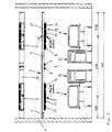
- eine Frontansicht einer erfindungsgemäßen Versorgungseinheit, die in einem Raum an der Wand befestigt ist,
- Fig. 2
- eine alternative Anordnung der Versorgungseinheit
gemäß
Figur 1, - Fig. 3
- eine vergrößerte Seitenansicht der erfindungsgemäßen Versorgungseinheit,
- Fig. 4
- eine vergrößerte Frontansicht, teilweise im Schnitt, der Versorgungseinheit und
- Fig. 5
- eine Seitenansicht im Schnitt entlang der Linie VI -
VI gemäß
Figur 1 mit eingesetzter Raumleuchte.
- Fig. 1
- 2 shows a front view of a supply unit according to the invention which is fastened to the wall in a room,
- Fig. 2
- an alternative arrangement of the supply unit according to Figure 1,
- Fig. 3
- an enlarged side view of the supply unit according to the invention,
- Fig. 4
- an enlarged front view, partly in section, the supply unit and
- Fig. 5
- a side view in section along the line VI - VI of Figure 1 with the room lamp inserted.
In den Figuren sind gleiche und entsprechende Bauteile mit denselben Bezugszeichen versehen. Die in den Figuren angegebenen Maßangaben sind beispielhaft zu verstehen und nicht auf die konkret angegebenen Maße beschränkt.The same and corresponding components are shown in the figures provided the same reference numerals. The indicated in the figures Dimensions are to be understood as examples and are not based on limited the dimensions specified.
Wie aus den Figuren zu entnehmen ist, besteht die Versorgungseinheit
2 aus einem im wesentlichen L-förmigen Metallprofil.
Die Versorgungseinheit weist einen Grundsteg 2a auf, mit dem
diese an der Wand in bekannter Weise befestigbar ist. Dieses
kann beispielsweise durch Einhängen der Versorgungseinheit in
eine an der Wand festgeschraubten Befestigungsleiste erfolgen
(siehe Fig. 5). Hierzu ist auf der Rückseite des Grundstegs
durch einen Horizontalsteg 2b beabstandet ein querverlaufender
Einhängesteg 2c vorgesehen. Einstückig an dem Grundsteg 2a ist
ein Quersteg 2d angeformt, der in Einbaulage im wesentlichen
horizontal verläuft und sich von der Wand weg erstreckt.As can be seen from the figures, there is the
Ant vorderen Ende des Querstegs kann eine in den Figuren 1 und
2 vorderseitig sichtbare Abdeckung 3 über eine Schnappverbindung
eingesetzt werden. Die Abdeckung 3 ist an dem vorderen
Ende und in einem spitzen Winkel in Richtung der Wand 1 umgebogen,
so daß der frei Schenkel der Abdeckung 3 in Richtung
der Wand ragt. Vorliegend ist der freie Schenkel der Abdeckung
3 bogenförmig ausgebildet. Am äußeren Ende des freien Schenkels
ist die Abdeckung 3 mit einer Aufnahme versehen, in die
ein weiter unten zu beschreibendes Raumlicht lösbar einsetzbar
ist.At the front end of the crossbar can be one in Figures 1 and
2
Der wesentliche Erfindungsgedanke wird nunmehr unter Bezug auf
die Figuren 1 und 2 näher erläutert. Wie diesen Figuren zu
entnehmen ist, erstreckt sich die Versorgungseinheit über 4030
mm entlang nahzu der gesamten kopfseitigen Wand 1. Die Versorgungseinheit
ist an dem längsseitigen Ende in der Nähe der
Wand 4 mit einer Anschlußseite 5 versehen, mit denen die Versorgungseinheit
mit den aus der Wand ragenden Leitungen verbunden
ist. Es kann sich hierbei sowohl um Strom-, Gas-, Vakuum- und Druckleitungen handeln.The essential inventive concept will now be described with reference to
Figures 1 and 2 explained in more detail. Like these figures too
the supply unit extends over 4030
mm along almost the entire
Diese Leitungen werden innerhalb der Versorgungseinheit bis
zum freien Ende weitergeführt. Etwa in der Raummitte ist die
versorgungseinheit auf ihrer Unterseite unterhalb des Querstegs
2b mit einem Druckluftanschluß 6 und einem Sauerstoffanschluß
7 in herkömmlicher Art und Weise versehen. Diese sind
von beiden Betten 8 und 9 leicht zugänglich. Neben den Betten
sind zwischen diesen zwei rollbare Kommoden 10 und 11 angeordnet.These lines are up within the supply unit
continued to the free end. It is in the middle of the room
supply unit on its underside below the
Unterhalb des Querstegs 2b der Versorgungseinheit sind mittig
über dem stirnseitigen Ende der Betten 8 und 9 gondelartige
Unterbauten 12 und 13 an der Versorgungseinheit 2 vorgesehen.
Die gondelartigen Unterbauten 12, 13 sind zwar fixiert, können
aber entlang der Längsachse der Versorungseinheit 2 verschoben
werden. An der in Blickrichtung vorderseitigen schrägen Seite
der Unterbauten 12 und 13 sind die zuvor besagten Anschlußeinrichtungen
14 für die Stromversorgung, elektrische Signalverbindungen,
Meßleitungen und dergleichen vorgesehen. Zwischen
den Anschlußeinrichtungen 14 ist mittig ein Leselicht 15
vorgesehen, dessen Licht über ein Raster bekannter Art und
Weise gestreut wird.Below the
In dem Quersteg 2d sind jeweils zwei nicht näher dargestellte
Langlöcher von etwa 300 mm Länge vorgesehen, deren Mitte durch
die vertikal verlaufenden, gestrichelten Linien angedeutet
ist. Gleichzeitig ist in bezug auf diese Mitte der Verstellbereich
der Unterbauten mit 150mm zur Mitte der Versorgungseinheit
2 und mit 300mm von der Mitte Weg angegeben. Durch die
Langlöcher werden die Versorgungsleitungen aus der Versorgungseinheit
2 in die Unterbauten 12 und 13 zu den Anschlußeinrichtungen
14 und den Leuchten geführt.Two
Die etwa 1000mm langen Unterbauten können in einem Bereich von
+/- 300 mm in jeder Richtung verschoben werden, um diese immer
mittig oberhalb des Kopfendes der Betten 8 und 9 zu plazieren.The approximately 1000mm long substructures can be in a range of
+/- 300 mm can be shifted in any direction to always get this
to be placed in the middle above the head end of
Wenn beispielsweise die Raumaufteilung, wie in Figur 2 dargestellt,
es erforderlich macht, daß die Kommoden 10 und 11
außenseitig von den Betten 8 und 9 angeordnet sind, werden die
Unterbauten 12 und 13 durch Lösen der Muttern axial in Längsrichtung
der Versorgungseinheit 2 jeweils zur Mitte verschoben,
bis diese wieder oberhalb des kopfseitigen Endes der
nunmehr neu plazierten Betten 8 und 9 gelegen sind. Das Loch
oder Langloch ermöglicht dabei einen genügend weiten Verstellbereich
und verhindert gleichzeitig ein Einklemmen der Versorgungsleitungen
an den Übergangskanten.For example, if the floor plan, as shown in Figure 2,
it requires chests of
Unter Bezug auf die Figuren 3 und 4 wird nunmehr die Befestigung
des Unterbaus 13 an der Versorgungseinheit 2 genauer
erläutert. Der Quersteg 2d weist an seiner in Einbaulage unteren
Seite zwei im Querschnitt T-förmige Längsnuten 2e und 2f
auf, in welchen mit einem Flachkopf versehene Befestigungsbolzen
20 längsverschieblich geführt sind; der Flachkopf der
Befestigungsbolzen liegt innenseitig auf den Schenkeln der
Längsnuten 2e, 2f auf und das Gewindeende der Bolzen ragt aus
den Längsnuten 2e, 2f hervor. Der Unterbau 13 wird nach Art
einer Schublade an der Versorgungseinheit 2 gehalten. Zu diesem
Zweck ist an dem Befestigungsbolzen 20 ein Blech 21 festgeschraubt,
das im wesentlichen eine L-förmige Gestalt aufweist.
Der Längsschenkel des Blechs 21 ist an der Unterseite
des Querstegs 2d durch den Befestigungsbolzen angeschraubt.
Etwa mittig weist das Blech 21 an seinem Längsschenkel eine
Stufe auf, um einen Auflagebereich zu bilden, der in einen in
Einbaulage vertikal verlaufenden Vertikalsteg übergeht. In dem
Vertikalsteg ist ein sich in Betrachtungsrichtung der Figur 5
erstreckender Längsschlitz 22 vorgesehen. In diesen Längsschlitz
22 ist ein Stift 23 längsverschieblich geführt, der
den Vertikalsteg des Blechs 21 mit einem Seitenblech des Unterbaus
verbindet. Das Seitenblech weist im Querschnitt gesehen
eine L-förmige Gestalt auf, mit einem in Einbaulage gelegenen
horizontalen Steg, der in Einbaulage auf dem stufenartig
abgesenkten Teil des Blechs 21 aufliegt, und einem sich daran
anschließenden vertikalen Steg. Zwischen dem horizontalen Steg
und der Stufe des Blechs 21 ist ein Gleitlager 25 vorgesehen,
um das Abziehen des Unterbaus von der Wand zu vereinfachen.
Der Unterbau 13 ist an dem nicht dargestellten anderen Stirnende
mit einer spiegelbildlich ausgebildeten Anordnung befestigt.
Die an dem Unterbau vorgesehenen Seitenbleche 24
liegen also in Einbaulage auf den Stufenblechen 21 verschieblich
auf.With reference to Figures 3 and 4 is now the attachment
of the
Zum Versetzen der Unterbauten werden diese schubladenartig
ausgezogen und die auf den Befestigungsbolzen 20 angeordneten
Muttern werden gelöst, so daß die Unterbauten 12, 13 entlang
der Längsachse der Versorgungseinheit 2 verschoben werden
können. In der neuen Position werden die Bolzen 20 wieder
angezogen, um den Unterbau 13 an der neu gewünschten Stelle zu
fixieren. Das Seitenblech 24 ist vorliegend mit einer Abdeckkappe
26 verdeckt, die auf die stirnseitigen Enden des Unterbaus
aufschnappbar sind.To move the substructures, they become drawer-like
pulled out and arranged on the mounting
In der Figur 3, die eine Seitenansicht der Versorgungseinheit
2 und des Unterbaus 13 darstellt, ist der Unterbau 13 in seiner
ausgezogenen Stellung gestrichelt dargestellt.In Figure 3, which is a side view of the
Wie besonders gut der Figur 5 zu entnehmen ist, kann in die
obere freie Öffnung der Versorgungseinheit 2 ein nach oben
strahlendes Raumlicht eingesetzt werden. Von diesem Raumlicht
27 sind die Fassungen 28 für die Leuchtstoffröhren sichtbar.
Das Raumlicht 27 und die notwendigen Aggregate werden in bekannter
Weise in der Versorgungseinheit 2 befestigt. An der in
Einbaulage nach vorne gerichteten Schrägseite des Unterbaus 13
ist schließlich ein Leselicht mit einem Raster 30 vorgesehen.
Schließlich ist an der Unterseite des Unterbaus 13 eine Steckdose
31 eingelassen.As can be seen particularly well in FIG. 5, can be seen in FIG
upper free opening of the
Die Erfindung ermöglicht es erstmalig, sämtliche für die Versorgung eines Patienten notwendigen Anschlusseinrichtungen in dem Anbau vorzusehen und bedarfsgerecht logistisch optimal oberhalb des Kopfendes des oder der Betten in Abhängigkeit von der Raumgeometrie und der gewünschten Aufstellung der Betten zu positionieren. So ist es auch denkbar ISDN- und Telefonanschlüsse und dergleichen in dem Anbau vorzusehen. The invention makes it possible for the first time to supply everything connection equipment necessary for a patient to provide for the cultivation and logistically optimal as required above the head of the bed or beds depending on the room geometry and the desired placement of the beds to position. So it is also conceivable ISDN and telephone connections and the like to be provided in the cultivation.
- 11
- Wandwall
- 22nd
- VersorgungseinheitSupply unit
- 2a2a
- GrundstegLanding stage
- 2b2 B
- HorizontalstegHorizontal web
- 2c2c
- EinhangstegHook-in bar
- 2d2d
- QuerstegCrossbar
- 2e2e
- LängsnutLongitudinal groove
- 2f2f
- LängsnutLongitudinal groove
- 33rd
- Abdeckungcover
- 44th
- Wandwall
- 55
- AnschlußseiteConnection side
- 66
- DruckluftanschlußCompressed air connection
- 77
- SauerstoffanschlußOxygen connection
- 88th
- Bettbed
- 99
- Bettbed
- 1010th
- KommodeDresser
- 1111
- KommodeDresser
- 1212th
- UnterbauSubstructure
- 1313
- UnterbauSubstructure
- 1414
- AnschlußeinrichtungConnection device
- 1515
- LeselichtReading light
- 1616
- HängeschrankWall cupboard
- 1717th
- HängeschrankWall cupboard
- 1818th
- HängeschrankWall cupboard
- 2020th
- BefestigungsbolzenMounting bolts
- 2121
- Blech sheet
- 2222
- LängsschlitzLongitudinal slot
- 2323
- Stiftpen
- 2424th
- SeitenblechPage sheet
- 2525th
- Gleitlagerbearings
- 2626
- Abdeckungcover
- 2727
- RaumlichtRoom light
- 2828
- FassungFrame
- 3030th
- RasterGrid
- 3131
- Steckdosesocket
Claims (8)
daß der Quersteg (2d) mindestens ein Loch aufweist, und daß im Bereich des Lochs ein Anbau in Längserstreckungsrichtung der Versorgungseinheit (2) verschieblich fixierbar ist, an dem Anschlußeinrichtungen (14), Leuchten und dergleichen vorgesehen sind, die durch das Loch mit den Versorgungsleitungen verbindbar sind.Supply unit (2), in particular for the care of patients in the nursing field, consisting of at least one, preferably channel-like, profile for receiving and guiding supply lines, which has a base web (2a) which can be fastened to a substrate and extends in the longitudinal direction and at least one essentially transversely to the Base web (2a) has transverse web (2d), characterized in that
that the crosspiece (2d) has at least one hole, and that in the area of the hole an attachment in the longitudinal direction of the supply unit (2) can be slidably fixed, on which connection devices (14), lights and the like are provided, which pass through the hole with the supply lines are connectable.
Applications Claiming Priority (2)
| Application Number | Priority Date | Filing Date | Title |
|---|---|---|---|
| DE29918977U | 1999-10-29 | ||
| DE29918977U DE29918977U1 (en) | 1999-10-29 | 1999-10-29 | Supply unit |
Publications (1)
| Publication Number | Publication Date |
|---|---|
| EP1096629A1 true EP1096629A1 (en) | 2001-05-02 |
Family
ID=8080880
Family Applications (1)
| Application Number | Title | Priority Date | Filing Date |
|---|---|---|---|
| EP00122764A Withdrawn EP1096629A1 (en) | 1999-10-29 | 2000-10-19 | Supply unit |
Country Status (2)
| Country | Link |
|---|---|
| EP (1) | EP1096629A1 (en) |
| DE (1) | DE29918977U1 (en) |
Cited By (3)
| Publication number | Priority date | Publication date | Assignee | Title |
|---|---|---|---|---|
| EP1923622A2 (en) * | 2006-11-15 | 2008-05-21 | TRILUX GmbH & Co. KG | Media distributor with interchangeable lights |
| EP2669572A1 (en) | 2012-05-31 | 2013-12-04 | TRILUX Medical GmbH & Co. KG | Supply unit with a lighting system |
| DE102013223506A1 (en) | 2013-11-18 | 2015-05-21 | Trilux Medical Gmbh & Co. Kg | Supply unit with displaceable light source |
Citations (4)
| Publication number | Priority date | Publication date | Assignee | Title |
|---|---|---|---|---|
| WO1986003539A1 (en) * | 1984-12-12 | 1986-06-19 | MTD-PRODUKTER I SMA^oLAND AB | Method of preparing a hospital room or the like |
| WO1989007357A1 (en) * | 1988-02-04 | 1989-08-10 | Astra Meditec Ab | Flexible panel for electric and gas outlets |
| US4905433A (en) * | 1988-08-29 | 1990-03-06 | Hospital Systems, Inc. | Hospital head wall system |
| EP0739618A1 (en) * | 1995-04-24 | 1996-10-30 | TRILUX-LENZE GmbH & Co. KG | Supply unit for sickrooms |
-
1999
- 1999-10-29 DE DE29918977U patent/DE29918977U1/en not_active Expired - Lifetime
-
2000
- 2000-10-19 EP EP00122764A patent/EP1096629A1/en not_active Withdrawn
Patent Citations (4)
| Publication number | Priority date | Publication date | Assignee | Title |
|---|---|---|---|---|
| WO1986003539A1 (en) * | 1984-12-12 | 1986-06-19 | MTD-PRODUKTER I SMA^oLAND AB | Method of preparing a hospital room or the like |
| WO1989007357A1 (en) * | 1988-02-04 | 1989-08-10 | Astra Meditec Ab | Flexible panel for electric and gas outlets |
| US4905433A (en) * | 1988-08-29 | 1990-03-06 | Hospital Systems, Inc. | Hospital head wall system |
| EP0739618A1 (en) * | 1995-04-24 | 1996-10-30 | TRILUX-LENZE GmbH & Co. KG | Supply unit for sickrooms |
Cited By (5)
| Publication number | Priority date | Publication date | Assignee | Title |
|---|---|---|---|---|
| EP1923622A2 (en) * | 2006-11-15 | 2008-05-21 | TRILUX GmbH & Co. KG | Media distributor with interchangeable lights |
| EP1923622A3 (en) * | 2006-11-15 | 2012-11-14 | TRILUX GmbH & Co. KG | Media distributor with interchangeable lights |
| EP2669572A1 (en) | 2012-05-31 | 2013-12-04 | TRILUX Medical GmbH & Co. KG | Supply unit with a lighting system |
| DE102013223506A1 (en) | 2013-11-18 | 2015-05-21 | Trilux Medical Gmbh & Co. Kg | Supply unit with displaceable light source |
| WO2015071452A1 (en) | 2013-11-18 | 2015-05-21 | Trilux Medical Gmbh & Co. Kg | Supply unit comprising a movable light source |
Also Published As
| Publication number | Publication date |
|---|---|
| DE29918977U1 (en) | 2000-02-17 |
Similar Documents
| Publication | Publication Date | Title |
|---|---|---|
| EP0107162B1 (en) | Work table | |
| DE3402885C2 (en) | Free-standing supply column for medical purposes and holder | |
| EP0242568B1 (en) | Device for the set-up of workplaces with different supply connections | |
| EP2010838A2 (en) | System for securing furniture and implements that risk tilting | |
| DE10358622B3 (en) | Modular support frame for bathtub or shower tub has side profiles and push-fit corner fittings | |
| EP2248504B1 (en) | Medical supply unit with built-in modules | |
| EP1096629A1 (en) | Supply unit | |
| DE10314685B4 (en) | Media supply system | |
| EP1587194A2 (en) | Installation element for accomodating supply lines | |
| DE202006009561U1 (en) | Fire protection cabinet, comprises cabinet body, which has one door, two side panels, base, cover plate and rear wall, assembly elements are provided on inner side of cabinet body for admission of installations | |
| WO2005074749A1 (en) | Furniture-type product display device | |
| DE102012109334A1 (en) | Lifting system for a height-adjustable workstation system and workstation system with such a lifting system | |
| EP1612901B1 (en) | Supply device for supplying medical supplies | |
| EP2543352B1 (en) | Medical supply device | |
| EP0980170A2 (en) | Door installation especially door interphone | |
| DE20319410U1 (en) | Modular carrying frame for bathing tub or shower tray, assembled of straight and angular elements and height adjustable legs | |
| AT1117U1 (en) | KITCHEN ARRANGEMENT | |
| DE1690171C3 (en) | Combined connection device for different types of supply systems | |
| DE10165022B4 (en) | Device for installing supply lines has system of prefabricated elements with channels below ceiling, above normally reachable height for supply and/or data lines, columns to workstations | |
| EP1473012B1 (en) | Tripod head for medical ceiling frame with mounting device for sockets | |
| DE202004013513U1 (en) | Support structure for a modular kitchen system e.g. in a caravan comprises a first closed frame having vertical lateral frame elements, and a second closed frame having horizontal lateral frame elements | |
| DE20313111U1 (en) | Room module for open-plan office, has support frame with side walls supported on floor and joined to ceiling panel | |
| DD296611A5 (en) | CONSTRUCTION WALL WITH REMOVAL DEVICES FOR INTENSIVE MEDICINE | |
| DE202019001131U1 (en) | Wall furniture for TV and audio / video equipment | |
| EP1430578A1 (en) | Switchgear cabinet |
Legal Events
| Date | Code | Title | Description |
|---|---|---|---|
| PUAI | Public reference made under article 153(3) epc to a published international application that has entered the european phase |
Free format text: ORIGINAL CODE: 0009012 |
|
| AK | Designated contracting states |
Kind code of ref document: A1 Designated state(s): DE ES FR GB IT NL |
|
| AX | Request for extension of the european patent |
Free format text: AL;LT;LV;MK;RO;SI |
|
| 17P | Request for examination filed |
Effective date: 20010511 |
|
| AKX | Designation fees paid |
Free format text: DE ES FR GB IT NL |
|
| STAA | Information on the status of an ep patent application or granted ep patent |
Free format text: STATUS: THE APPLICATION IS DEEMED TO BE WITHDRAWN |
|
| 18D | Application deemed to be withdrawn |
Effective date: 20080503 |