EP1096376A2 - Snapshot arbiter mechanism - Google Patents
Snapshot arbiter mechanism Download PDFInfo
- Publication number
- EP1096376A2 EP1096376A2 EP00123353A EP00123353A EP1096376A2 EP 1096376 A2 EP1096376 A2 EP 1096376A2 EP 00123353 A EP00123353 A EP 00123353A EP 00123353 A EP00123353 A EP 00123353A EP 1096376 A2 EP1096376 A2 EP 1096376A2
- Authority
- EP
- European Patent Office
- Prior art keywords
- interrupt
- block
- register
- priority
- snapshot
- Prior art date
- Legal status (The legal status is an assumption and is not a legal conclusion. Google has not performed a legal analysis and makes no representation as to the accuracy of the status listed.)
- Withdrawn
Links
Images

Classifications
-
- G—PHYSICS
- G06—COMPUTING; CALCULATING OR COUNTING
- G06F—ELECTRIC DIGITAL DATA PROCESSING
- G06F9/00—Arrangements for program control, e.g. control units
- G06F9/06—Arrangements for program control, e.g. control units using stored programs, i.e. using an internal store of processing equipment to receive or retain programs
- G06F9/46—Multiprogramming arrangements
- G06F9/48—Program initiating; Program switching, e.g. by interrupt
- G06F9/4806—Task transfer initiation or dispatching
- G06F9/4812—Task transfer initiation or dispatching by interrupt, e.g. masked
-
- G—PHYSICS
- G06—COMPUTING; CALCULATING OR COUNTING
- G06F—ELECTRIC DIGITAL DATA PROCESSING
- G06F13/00—Interconnection of, or transfer of information or other signals between, memories, input/output devices or central processing units
- G06F13/14—Handling requests for interconnection or transfer
- G06F13/20—Handling requests for interconnection or transfer for access to input/output bus
- G06F13/24—Handling requests for interconnection or transfer for access to input/output bus using interrupt
- G06F13/26—Handling requests for interconnection or transfer for access to input/output bus using interrupt with priority control
Definitions
- This invention relates to digital processors, and more particularly relates to methods for servicing multiple interrupts on a priority basis.
- Priority based request arbitration systems determine the next request to be serviced, i.e., the "winner,” based upon which request priority is highest, pending and enabled. Priority assignments are generally based on degrees of importance, in this case of requests. If multiple requests are programmed to the same priority, fairness protocols are used to determine the next winner. A mechanism is fair when any given request is not serviced twice until all pending requests are serviced once. Such arbitration systems are frequently used in digital processor interrupt servicing systems. In fact, throughout this document the term “request” and “interrupt” are used synonymously (an interrupt is a request for service).
- the simplest fairness protocol is system based and ensures that a request does not occur twice for a predetermined length of time.
- This type of fairness includes Rate Monotonic Scheduling Theory (Louis Sha from Carnigee Melon University). However, for many systems, requests are not able to be deterministically scheduled a priori.
- FCFS First Come First Served
- the present invention provides a method for servicing multiple interrupt requests for a central processing unit in a digital processor system.
- the method includes the following steps. First, storage locations are provided for indicating at least some of one or more of the interrupt requests that are pending. The storage locations are loaded with indications of pending interrupt requests when the storage location is storing no pending interrupt request indications. Indications of pending interrupt requests are removed from the storage location when they are serviced. In implementations including preemption, indications of interrupt requests may be added to the storage location if such interrupt requests are of a priority higher than any interrupt request indication in the storage location.
- the present invention is equally applicable to any request/grant arbitration protocol.
- the preferred embodiment of the present invention provides a method for servicing multiple interrupts for a central processing unit ("CPU") in a digital processing system.
- the method utilizes a register, called herein the “snapshot register,” and designated “snapshot_reg.”
- the method includes the following steps:
- the snapshot register can be provided with little additional gate count since it can be combined with synchronization flip flops at the request synchronizer. Also, since no bits are added to the priority field, the preferred embodiment can run faster than systems implementing prior art methods. The preferred embodiment has also added a preemption mechanism that such prior art methods do not provide.
- FIG. 1 is a block diagram showing a CPU system with a CPU 10 talking to a Request Handler 12 through a bus interface 14.
- the Request Handler 12 receives different requests INT0, INT1, INT2, ... INTN, from other parts of the system, which are not shown, since they are not relevant to the instant invention.
- the CPU 10 has only one hardware interrupt and the responsibility of the Request Handler 12 is to route multiple requests to the CPU 10 in a fair and efficient manner.
- the fairness mechanism used by the Request Handler 12 implements the preferred embodiment of the present invention.
- the Request Handler 12 receives the address bus, data in and data out buses, and the control signals from the CPU 10 through the Bus interface 14. These signals are used to read and write out of the registers of the Request Handler 12.
- the Request Handler 12 processes the next interrupt to be serviced by the CPU 10 based on the contents of the registers and on the system requests.
- the Request Handler 12 interrupts the CPU 10.
- the CPU 10 then reads the Interrupt ID (IID) register 22, described in detail in the following section, to determine which peripheral in the system needs to be serviced.
- IID Interrupt ID
- the read from the IID register 22 also serves as an Interrupt Acknowledge from the CPU 10.
- a hardware mechanism if existing, could also serve as a method of acknowledging the interrupt by the CPU 10. Either level sensitive or edge sensitive requests could be used by the peripherals to talk to the Request Handler 12.
- the Interrupt service routine software needs to take action to release the request by the peripheral.
- the Request Handler 12 produces one output, INTRQ, on line 28 which is used to interrupt the CPU.
- the Request Handler 12 contains the following registers:
- IMR Interrupt Mask register
- FIG. 2 shows a system with a CPU 10' talking to a Request Handler 12' through a bus interface 14'.
- the CPU 10' is capable of receiving two interrupts called the IRQ interrupt and the FIQ interrupt, generated in response to requests INT0, INT1, INT2, ... INTN, from different parts of the system (not shown.
- Snapshot Logic 26' of the Request Handler 12' produces two outputs, IRQ and FIQ, on lines 40 and 42, respectively, based on the status of the requests and the values in certain registers in the system.
- Interrupt Mask register 16'
- Interrupt Priority registers IPR
- IID IRQ Interrupt ID register
- FIQ Interrupt ID register 22' the Interrupt ID register 22'
- Interrupter register INTR
- These registers have the same function as the corresponding registers in Figure 1, with the IRQ Interrupt ID register (IID) 21' and the FIQ Interrupt ID register 22' performing a similar function to the IID register 22 of Figure 1, but setting a bit only if the interrupt is to be an IRQ interrupt or an FIQ interrupt, respectively.
- the software executed in the CPU 10' can program each interrupt to be either an IRQ or an FIQ interrupt by setting a bit in an IPR register 18' - 20'. This allows the Request Handler 12' to route a request as either an IRQ interrupt or an FIQ interrupt.
- Request Handler 12 The following section describes the Request Handler 12, and the fairness mechanism used to determine the next request to be serviced in more detail. The principles described in connection with Request Handler 12 also apply to Request Handler 12'.
- FIG. 3 is a block diagram showing the construction of the Snapshot Logic 26.
- the Snapshot Logic 26 takes inputs from the interrupt mask register 16, the Interrupt Priority registers 18 - 20, the Interrupt ID registers 22, and the system interrupts INT[N:0].
- the Snapshot logic 26 processes the system interrupts and generates interrupts, INTRQ, to the CPU 10 ( Figure 1).
- the Snapshot Logic 26 includes the following blocks: an Interrupt Synchronizer block 50, an Interrupt Masker block 52, a Snapshot Register 54, an Interrupt Generation block 56, an Interrupt Preemption block 58, a Zero Detect block 60, a Snapshot Enable Block 62 and a Priority Encoder block 64.
- Interrupt Synchronizer block 50 In single CPU interrupt operation, synchronous and asynchronous system interrupts INT[N:0] pass into the Interrupt Synchronizer block 50. This block synchronizes the interrupts to the system clock.
- the Interrupt Masker block 52 performs a bit wise ANDing of the intr[N:1] bits and the corresponding interrupt mask register bits imr[N:1].
- the output of the Interrupt Masker block 52, itmr[N:l] represents the currently active and enabled interrupts. This N bit value is passed to the Snapshot Register block 54 and to the Interrupt Preemption block 58.
- the Snapshot Register block 54 receives itmr[N:l] from the Interrupt Masker block 52 and an enable input EN[N:1] from the Snapshot Enable block 62., and outputs an N bit value, intss[N:1], identifying the currently active and enabled interrupts, i.e., a "snapshot" of the currently active and enabled interrupts. This "snapshot" of the currently active and enabled interrupts is sampled or modified under various conditions as determined by the Snapshot Enable block 62.
- the Priority Encoder block 64 encodes the values in the Interrupt Priority registers 18 - 20 ( Figure 1).
- the priority encoder outputs for each system interrupt an N bit value ipr_enc[n][N:l], where n is a value from 1 to N identifying the particular interrupt.
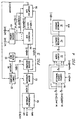
- FIG. 4 is a block diagram of the INTR Generation block 56.
- the INTR Generation block 56 includes four sub-blocks, a Highest Priority sub-block 70, a Match Highest sub-block 72, a Leftmost Resolver sub-block 74 and a Generate Interrupt sub-block 76 (see Figure 4).
- the Highest Priority sub-block 70 does a bitwise OR-ing of the priority encoded interrupts ipr_enc[n][N:l] and the output of the Snapshot Register block 54, intss[N:1].
- the resultant value, highest[N:1] represents the highest interrupt priority level in the snapshot register.
- the Highest Priority sub-block 70 output, highest[N:1], and the output of the Priority Encoder block 64, ipr_enc[n][N:l], are fed to the Match Highest sub-block 72.
- the Match Highest sub-block 72 compares the priority of the snapshot to the value of the Highest Priority sub-block 70. A bit is set for each interrupt which matches the highest value. The results of the match are bitwise ANDed with the snapshot register and the enabled interrupts to ensure the interrupts with the highest priority are currently active and enabled. This final result is provided as an N bit output of the Match Highest sub-block 72.
- the Leftmost Resolver sub-block 74 receives the N bit output from the Match Highest sub-block 72 and determines which of the interrupts is the leftmost in the N-bit field of ones and zeros. In the logic convention adopted for the purposes of this discussion Intr N is considered the leftmost, and Intr_l is considered the rightmost. This is arbitrary, but, of course, some convention must be adopted.
- the Leftmost Resolver sub-block 74 outputs an N-bit value with one bit enabled to correspond to the winning leftmost interrupt. This value is stored in the Interrupt ID register 22 ( Figure 1) and provided to the Generate Interrupt sub-block 76.
- the Generate Interrupt sub-block 76 asserts the CPU interrupt line INTR.
- the flow in the INTR Generation block 56 of Figure 4 is illustrated by the following example.
- N 3 and that there are three interrupt priority levels.
- Intr_3 and Intr_1 have been set to the highest priority and that Intr_2 has been set to the lowest priority.
- All three of the interrupts are currently in the Snapshot Register block 54 and the interrupt priority levels have been encoded in Priority Encoder block 64.
- the 11 value is passed to the Match Highest sub-block 72 and the interrupt priority levels are compared.
- the Match Highest sub-block 72 produces in an output of 101 since intr_3 and intr_l are at the highest priority.
- the Leftmost Resolver sub-block 74 determines that intr_3 is the "leftmost" interrupt and outputs a value of 100.
- the 100 is stored in the Interrupt ID registers 22 and the Generate Interrupt sub-block 76 asserts the INTR line.
- the Interrupt Preemption block 58 is comprised, essentially, of a Higher Detect sub-block 78. It takes the output, ipr_enc[n][N:l], of the Priority Encoder block 64, the output, itmr[N:l], of the Interrupt Masker block 52, and the highest interrupt value, highest[N:1], from the INTR Generation block 56.
- the encoded interrupts are fed to the Higher Detect sub-block 78. This block compares the encoded interrupts with the highest signal. For each current interrupt higher in priority than all of the interrupts in the snapshot register, a bit is set corresponding to the left to right convention used through the rest of the logic.
- the N bit output, preempt[N:1] is fed to the snapshot enable logic which updates the snapshot register with these new bits.
- the Snapshot Enable block 62 can now be better defined. Several conditions cause the snapshot to be updated. These conditions are:
- the snapshot logic of Figure 6 includes the following blocks: an Interrupt Synchronizer block 80, an Interrupt Masker block 82, a Snapshot Register 84, a Zero Detect block 90, a Snapshot Enable Block 92 and a Priority Encoder block 94.
- the snapshot logic of Figure 6 includes an IRQ Interrupt Generation block 96, an IRQ Interrupt Preemption block 98, and an FIQ Interrupt Generation block 100, and an FIQ Interrupt Preemption block 102.
- the method may be applied to systems having any number of CPU interrupts. Assuming the number of such interrupts in a given system is N, then log 2 N bits would need to be reserved to identify the CPU interrupt. Also note that these bits may be located in the interrupt priority registers, as in the preferred embodiment, but they could be located elsewhere, so long as they are available to the priority encoder block of such system to create separate enable signals for each interrupt.
- each instance of the generation and preemption block performs its logical operations only for the system interrupts in its class.
- three system interrupts and intr_3 and intr_2 are IRQ interrupts
- intr_l is an FIQ interrupt
- 3 and 2 is processed by the IRQ interrupt generation and preemption blocks.
- Interrupt 1 is processed by the FIQ interrupt generation and preemption blocks.
- Each instance of the interrupt generation block stores the winning interrupt in the correct ID register and asserts its CPU interrupt line.
- Each interrupt generation block passes its "highest" signal to associated interrupt preemption circuitry.
- Each interrupt preemption block Outputs a preempt signal which corresponds to only its related system interrupts.
- the output of each preemption block is bitwise or-ed to create a preempt signal for the snapshot enable logic.
- the snapshot update enable block is modified to operate in the following manner:
Landscapes
- Engineering & Computer Science (AREA)
- Theoretical Computer Science (AREA)
- Software Systems (AREA)
- Physics & Mathematics (AREA)
- General Engineering & Computer Science (AREA)
- General Physics & Mathematics (AREA)
- Bus Control (AREA)
Abstract
Description
- This invention relates to digital processors, and more particularly relates to methods for servicing multiple interrupts on a priority basis.
- Priority based request arbitration systems determine the next request to be serviced, i.e., the "winner," based upon which request priority is highest, pending and enabled. Priority assignments are generally based on degrees of importance, in this case of requests. If multiple requests are programmed to the same priority, fairness protocols are used to determine the next winner. A mechanism is fair when any given request is not serviced twice until all pending requests are serviced once. Such arbitration systems are frequently used in digital processor interrupt servicing systems. In fact, throughout this document the term "request" and "interrupt" are used synonymously (an interrupt is a request for service).
- The simplest fairness protocol is system based and ensures that a request does not occur twice for a predetermined length of time. This type of fairness includes Rate Monotonic Scheduling Theory (Louis Sha from Carnigee Melon University). However, for many systems, requests are not able to be deterministically scheduled a priori.
- A second form of fairness protocol is "First Come First Served (FCFS)" (Udi Manber and Mary Vernon, University of Wisconsin). In this protocol, each time the source of the request loses, it increments a counter. The counter value is used as the least significant bits of the priority field to determine the next winner. When multiple requests are all of the same priority value the leftmost is selected as the winner. This mechanism is gate intensive and potentially slows the rate at which the next winner can be determined.
- Another mechanism commonly used in busses like Futurebus+ is "Round Robin" (Udi Manber and Mary Vernon, University of Wisconsin). In this protocol, a module checks if it lost and the winner is to the left (arbitrarily but consistently ordered) of itself. If so, it sets a round robin bit which is used as the least significant bit of the priority value to determine the winner. When multiple requests are all of the same priority value the leftmost is selected as the winner. This mechanism is a vast improvement over First Come First Served by reducing the effect on the amount of storage needed to determine fairness and also to reduce the time required to determine the winner.
- However, there is a need to further reduce the storage necessary, in most cases, and the time required to determine a winner in priority based request arbitration systems.
- The present invention provides a method for servicing multiple interrupt requests for a central processing unit in a digital processor system. The method includes the following steps. First, storage locations are provided for indicating at least some of one or more of the interrupt requests that are pending. The storage locations are loaded with indications of pending interrupt requests when the storage location is storing no pending interrupt request indications. Indications of pending interrupt requests are removed from the storage location when they are serviced. In implementations including preemption, indications of interrupt requests may be added to the storage location if such interrupt requests are of a priority higher than any interrupt request indication in the storage location.
- The present invention is equally applicable to any request/grant arbitration protocol.
- These and other features of the invention will be apparent to those skilled in the art from the following detailed description of the invention, taken together with the accompanying drawings.
-
- Fig. 1 is a block diagram showing a CPU system including a Request Handler in accordance with a preferred embodiment of the present invention, in which the CPU is capable of receiving one interrupt;
- Fig. 2 is a block diagram showing a CPU system including a Request Handler in accordance with a preferred embodiment of the present invention, in which the CPU is capable of receiving two interrupts;
- Fig. 3 is a block diagram showing the construction of
the Snapshot
Logic 26 of Figure 1; - Fig. 4 is a block diagram of the INTR
Generation block 56 of Figure 1; - Fig. 5 is a more detailed diagram of the
Interrupt Preemption block 58 of Figure 3; and - Fig. 6 is a block diagram showing a CPU system including a Request Handler in accordance with a preferred embodiment of the present invention, having multiple CPUs.
-
- The preferred embodiment of the present invention provides a method for servicing multiple interrupts for a central processing unit ("CPU") in a digital processing system. The method utilizes a register, called herein the "snapshot register," and designated "snapshot_reg." At a high level, the method includes the following steps:
- 1. take a sample of pending requests (snapshot_reg <-pending requests) anytime the snapshot register is empty (snapshot_reg=0).
- 2. remove requests from the snapshot register when they are serviced.
- 3. add requests to the snapshot register if they are higher priority than any request in the snapshot register (preemption).
-
- In the preferred embodiment, the snapshot register can be provided with little additional gate count since it can be combined with synchronization flip flops at the request synchronizer. Also, since no bits are added to the priority field, the preferred embodiment can run faster than systems implementing prior art methods. The preferred embodiment has also added a preemption mechanism that such prior art methods do not provide.
- Figure 1 is a block diagram showing a CPU system with a
CPU 10 talking to aRequest Handler 12 through abus interface 14. TheRequest Handler 12 receives different requests INT0, INT1, INT2, ... INTN, from other parts of the system, which are not shown, since they are not relevant to the instant invention. TheCPU 10 has only one hardware interrupt and the responsibility of the Request Handler 12 is to route multiple requests to theCPU 10 in a fair and efficient manner. The fairness mechanism used by the Request Handler 12 implements the preferred embodiment of the present invention. - The
Request Handler 12 receives the address bus, data in and data out buses, and the control signals from theCPU 10 through theBus interface 14. These signals are used to read and write out of the registers of theRequest Handler 12. TheRequest Handler 12 processes the next interrupt to be serviced by theCPU 10 based on the contents of the registers and on the system requests. - In this system, the
Request Handler 12 interrupts theCPU 10. TheCPU 10 then reads the Interrupt ID (IID)register 22, described in detail in the following section, to determine which peripheral in the system needs to be serviced. In this system, the read from theIID register 22 also serves as an Interrupt Acknowledge from theCPU 10. However, a hardware mechanism, if existing, could also serve as a method of acknowledging the interrupt by theCPU 10. Either level sensitive or edge sensitive requests could be used by the peripherals to talk to theRequest Handler 12. In the case of the level sensitive interrupts, the Interrupt service routine software needs to take action to release the request by the peripheral. - The
Request Handler 12 produces one output, INTRQ, online 28 which is used to interrupt the CPU. TheRequest Handler 12 contains the following registers: -
- The
CPU 10 can read from and write to this register. The IMR register 16 is N bits wide, where N is the number of system requests, and stores N bits referred to collectively as imr. Each of these bits corresponds to a unique interrupt. Each of the interrupts can be masked based on a value at the corresponding bit position in the register. If a request is masked, then it will not be allowed to participate in the servicing mechanism. -
-
- The
CPU 10 can only read from this register. The IID register 22 is also N bits wide, and stores N bits referred to collectively as id. Each of these bits corresponds to a unique interrupt. When an interrupt needs to be serviced by theCPU 10, theRequest Handler 12 asserts the INT output to theCPU 10, and a corresponding bit in theIID register 22 is also set. This bit is cleared on a read from theCPU 10 to this register. -
-
- The
CPU 10 can read from and write to each of the registers. Each register is k bits wide, where k is log 2 N, and stores a value ipr[n], where n is a value from 1 to N identifying the particular interrupt. The value in the IPR determines a priority between 0 and N- 1 for each of the interrupts from the system. -
-
- The
CPU 10 can read from this register. It stores N bits referred to collectively as intr, which indicate the current status of the requests from the system peripherals to theRequest Handler 12. The interrupts are either synchronized to the clock of theRequest Handler 12, or they can be asynchronous. -
- Figure 2 shows a system with a CPU 10' talking to a Request Handler 12' through a bus interface 14'. The CPU 10' is capable of receiving two interrupts called the IRQ interrupt and the FIQ interrupt, generated in response to requests INT0, INT1, INT2, ... INTN, from different parts of the system (not shown. In this system, Snapshot Logic 26' of the Request Handler 12' produces two outputs, IRQ and FIQ, on
lines - The following section describes the
Request Handler 12, and the fairness mechanism used to determine the next request to be serviced in more detail. The principles described in connection withRequest Handler 12 also apply to Request Handler 12'. - Figure 3 is a block diagram showing the construction of the
Snapshot Logic 26. TheSnapshot Logic 26, takes inputs from the interruptmask register 16, the Interrupt Priority registers 18 - 20, the Interrupt ID registers 22, and the system interrupts INT[N:0]. TheSnapshot logic 26 processes the system interrupts and generates interrupts, INTRQ, to the CPU 10 (Figure 1). TheSnapshot Logic 26 includes the following blocks: an InterruptSynchronizer block 50, an InterruptMasker block 52, aSnapshot Register 54, an InterruptGeneration block 56, an InterruptPreemption block 58, a Zero Detectblock 60, aSnapshot Enable Block 62 and aPriority Encoder block 64. - In single CPU interrupt operation, synchronous and asynchronous system interrupts INT[N:0] pass into the Interrupt
Synchronizer block 50. This block synchronizes the interrupts to the system clock. The output of the InterruptSynchronizer block 50, intr[N:1], is an N bit value which indicates the active system interrupts. - The Interrupt
Masker block 52 performs a bit wise ANDing of the intr[N:1] bits and the corresponding interrupt mask register bits imr[N:1]. The output of the InterruptMasker block 52, itmr[N:l], represents the currently active and enabled interrupts. This N bit value is passed to theSnapshot Register block 54 and to the InterruptPreemption block 58. - The
Snapshot Register block 54 receives itmr[N:l] from the InterruptMasker block 52 and an enable input EN[N:1] from the Snapshot Enable block 62., and outputs an N bit value, intss[N:1], identifying the currently active and enabled interrupts, i.e., a "snapshot" of the currently active and enabled interrupts. This "snapshot" of the currently active and enabled interrupts is sampled or modified under various conditions as determined by theSnapshot Enable block 62. - The
Priority Encoder block 64 encodes the values in the Interrupt Priority registers 18 - 20 (Figure 1). The Interrupt Priority registers contain the classification and priority level for each interrupt. For each interrupt the priority level is encoded as a field of ones and zeros. For a system where N=3, a priority of zero is represented as "000," a priority of one is "001," a priority of two is "011" and a priority of three is "111." The priority encoder outputs for each system interrupt an N bit value ipr_enc[n][N:l], where n is a value from 1 to N identifying the particular interrupt. - The output of the priority encoder is sent to the
INTR Generation block 56. Figure 4 is a block diagram of theINTR Generation block 56. TheINTR Generation block 56 includes four sub-blocks, aHighest Priority sub-block 70, a Match Highest sub-block 72, aLeftmost Resolver sub-block 74 and a Generate Interrupt sub-block 76 (see Figure 4). - The
Highest Priority sub-block 70 does a bitwise OR-ing of the priority encoded interrupts ipr_enc[n][N:l] and the output of theSnapshot Register block 54, intss[N:1]. The resultant value, highest[N:1], represents the highest interrupt priority level in the snapshot register. - The
Highest Priority sub-block 70 output, highest[N:1], and the output of thePriority Encoder block 64, ipr_enc[n][N:l], are fed to theMatch Highest sub-block 72. The Match Highest sub-block 72 compares the priority of the snapshot to the value of theHighest Priority sub-block 70. A bit is set for each interrupt which matches the highest value. The results of the match are bitwise ANDed with the snapshot register and the enabled interrupts to ensure the interrupts with the highest priority are currently active and enabled. This final result is provided as an N bit output of theMatch Highest sub-block 72. - The
Leftmost Resolver sub-block 74 receives the N bit output from the Match Highest sub-block 72 and determines which of the interrupts is the leftmost in the N-bit field of ones and zeros. In the logic convention adopted for the purposes of this discussion Intr N is considered the leftmost, and Intr_l is considered the rightmost. This is arbitrary, but, of course, some convention must be adopted. TheLeftmost Resolver sub-block 74 outputs an N-bit value with one bit enabled to correspond to the winning leftmost interrupt. This value is stored in the Interrupt ID register 22 (Figure 1) and provided to the Generate Interrupt sub-block 76. The Generate Interrupt sub-block 76 asserts the CPU interrupt line INTR. - The flow in the
INTR Generation block 56 of Figure 4 is illustrated by the following example. For the example it is assumed that N=3 and that there are three interrupt priority levels. It is also assumed that Intr_3 and Intr_1 have been set to the highest priority and that Intr_2 has been set to the lowest priority. All three of the interrupts are currently in theSnapshot Register block 54 and the interrupt priority levels have been encoded inPriority Encoder block 64. TheHighest Priority sub-block 70 ORs the priority levels of the three snapshot interrupts as shown, (intr_3=11) bitwise or (intr_2=00) bitwise or (intr_ 1=11) = 11. The 11 value is passed to the Match Highest sub-block 72 and the interrupt priority levels are compared. The Match Highest sub-block 72 produces in an output of 101 since intr_3 and intr_l are at the highest priority. TheLeftmost Resolver sub-block 74 determines that intr_3 is the "leftmost" interrupt and outputs a value of 100. The 100 is stored in the Interrupt ID registers 22 and the Generate Interrupt sub-block 76 asserts the INTR line. - The Interrupt
Preemption block 58, shown in Figure 5, is comprised, essentially, of a Higher Detect sub-block 78. It takes the output, ipr_enc[n][N:l], of thePriority Encoder block 64, the output, itmr[N:l], of the InterruptMasker block 52, and the highest interrupt value, highest[N:1], from theINTR Generation block 56. The encoded interrupts are fed to the Higher Detect sub-block 78. This block compares the encoded interrupts with the highest signal. For each current interrupt higher in priority than all of the interrupts in the snapshot register, a bit is set corresponding to the left to right convention used through the rest of the logic. The N bit output, preempt[N:1], is fed to the snapshot enable logic which updates the snapshot register with these new bits. - The
Snapshot Enable block 62 can now be better defined. Several conditions cause the snapshot to be updated. These conditions are: - A. Snapshot register bits are added to when:
- 1. The snapshot register is empty; the current interrupts are sampled.
- 2. The preemption circuitry detects active and enabled interrupts with higher priority so the corresponding snapshot bits are set.
- B. Snapshot register bits are removed when:
- 1. An interrupt service register is read; the corresponding interrupt bit are cleared.
- 2. An active interrupt's mask bit is cleared; the corresponding snapshot bit are cleared.
- 3. An interrupt is disabled before being serviced; the corresponding interrupt bit are cleared.
-
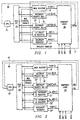
- In systems having multiple CPUs, multiple instances of the INTR generation block and the INTR preemption block are required in the snapshot logic blocks of such systems. Such systems have multiple interrupt classes, and there are separate interrupt generation and interrupt preemption blocks for IRQ interrupts and FIQ interrupts. An example of the snapshot logic for such a system is shown in Figure 6. As in the
Snapshot Logic Block 26 of Figure 3, the snapshot logic of Figure 6 includes the following blocks: an InterruptSynchronizer block 80, an InterruptMasker block 82, aSnapshot Register 84, a Zero Detectblock 90, aSnapshot Enable Block 92 and aPriority Encoder block 94. However, instead of a single Interrupt Generation block and a single Interrupt Preemption block, the snapshot logic of Figure 6 includes an IRQ InterruptGeneration block 96, an IRQ InterruptPreemption block 98, and an FIQ InterruptGeneration block 100, and an FIQ Interrupt Preemption block 102. - Only one snapshot register and one priority encoder is required for a multiple class system in which the snapshot logic Figure 6 is used. To differentiate between an FIQ interrupt and an IRQ interrupt, a bit is added to the interrupt priority register indicating whether the interrupt request is an FIQ or IRQ interrupt request. That bit is used to create separate FIQ enable signals ipr_enc[n][k:0] and IRQ enable signals ipr_enc[n][k:0] in the
Priority Encoder block 94, where, again, n is a value from 1 to N identifying the particular interrupt. ThePriority Encoder block 94 sends these N bit enable signals to the associated FIQ or IRQ logic blocks. The snapshot update enable block changes slightly to handle situations involved with multiple classes. - Note that the method may be applied to systems having any number of CPU interrupts. Assuming the number of such interrupts in a given system is N, then log2N bits would need to be reserved to identify the CPU interrupt. Also note that these bits may be located in the interrupt priority registers, as in the preferred embodiment, but they could be located elsewhere, so long as they are available to the priority encoder block of such system to create separate enable signals for each interrupt.
- With multiple interrupt classes each instance of the generation and preemption block performs its logical operations only for the system interrupts in its class. In the described circuitry assuming three system interrupts and intr_3 and intr_2 are IRQ interrupts, and intr_l is an FIQ interrupt, 3 and 2 is processed by the IRQ interrupt generation and preemption blocks. Interrupt 1 is processed by the FIQ interrupt generation and preemption blocks. Each instance of the interrupt generation block stores the winning interrupt in the correct ID register and asserts its CPU interrupt line. Each interrupt generation block passes its "highest" signal to associated interrupt preemption circuitry. Each interrupt preemption block Outputs a preempt signal which corresponds to only its related system interrupts. The output of each preemption block is bitwise or-ed to create a preempt signal for the snapshot enable logic. The snapshot update enable block is modified to operate in the following manner:
- A. Snaphot register bits are added to when:
- 1. The snapshot register is empty; the current interrupts are sampled.
- 2. The snapshot register does not contain any interrupts of a class; the current enabled interrupts of the class are added.
- 3. The preemption circuitry detects active and enabled interrupts with higher priority than other interrupts in the same class; the corresponding snapshot bits are set.
- B. Snapshot register bits are removed when:
- 1. An interrupt service register is read; the corresponding interrupt bit is cleared.
- 2. An active interrupt's mask bit is cleared; the corresponding snapshot bit is cleared.
- 3. An interrupt is disabled before being serviced; the corresponding interrupt bit is cleared.
-
- The following additional variations are possible for use in implementing the above described logic.
- 1. A write one to clear method could be used to clear serviced interrupts from the snapshot.
- 2. The interrupt synchronizer could be removed if the system interrupts were known to be synchronous or if an asynchronous interrupt generation mechanism was desired.
- 3. The priority encoder could be removed and raw priority values used or the encoding method could be modified to meet the particular needs of a given system.
- 4. The left to right resolver could be implemented as a right to left mechanism or any other fixed pattern of resolving which interrupt to service.
-
- Although the present invention and its advantages have been described in detail, it should be understood that various changes, substitutions and alterations can be made herein without departing from the spirit and scope of the invention as defined by the appended claims.
Claims (7)
- A method for servicing multiple interrupt requests for a central processing unit in a digital processor system, comprising the steps of:providing a storage locations for indicating at least some of one or more of said interrupt requests that are pending;loading said storage locations with indications of pending interrupt requests when said storage locations are storing no pending interrupt request indications; andremoving indications of pending interrupt requests from said storage locations when they are serviced.
- A method for servicing multiple interrupt requests as in Claim 1, further comprising the step of:assigning priority to interrupt requests.
- A method for servicing multiple interrupt requests as in Claim 1, further comprising the step of:adding indications of interrupt requests to said storage locations if such interrupt requests are of a priority higher than any interrupt request indication in said storage locations.
- A method for servicing multiple interrupt requests as in Claim 1, further comprising the steps of:selecting an interrupt request for which an indication is stored in said storage locations; andgenerating an interrupt for said selected interrupt request.
- A method for servicing multiple interrupt requests as in Claim 4, wherein said step of selecting is performed by selecting said interrupt request according to a predetermined procedure.
- A method for servicing multiple interrupt requests as in Claim 5, wherein:said step of loading is performed by storing said indications as bits, wherein each bit represents an indication, and said bits are stored in storage locations according to a predetermined arrangement; andsaid step of selecting is performed by selecting said interrupt request that occupies the left most storage location.
- A method for servicing multiple interrupt requests for a central processing unit in a digital processor system, comprising the steps of:assigning priority to interrupt requests;providing a register for storing indications of pending interrupts;synchronizing said interrupt requests that are pending;masking said pending interrupts;loading said masked, pending interrupts into said register if said masked, pending interrupts have a priority higher than any priority for which an indication is stored in said register;selecting an interrupt request for which an indication is stored in said register; and
generating an interrupt for said selected interrupt request.
Applications Claiming Priority (2)
| Application Number | Priority Date | Filing Date | Title |
|---|---|---|---|
| US16225799P | 1999-10-29 | 1999-10-29 | |
| US162257P | 1999-10-29 |
Publications (2)
| Publication Number | Publication Date |
|---|---|
| EP1096376A2 true EP1096376A2 (en) | 2001-05-02 |
| EP1096376A3 EP1096376A3 (en) | 2004-06-30 |
Family
ID=22584856
Family Applications (1)
| Application Number | Title | Priority Date | Filing Date |
|---|---|---|---|
| EP00123353A Withdrawn EP1096376A3 (en) | 1999-10-29 | 2000-10-27 | Snapshot arbiter mechanism |
Country Status (3)
| Country | Link |
|---|---|
| US (1) | US6651126B1 (en) |
| EP (1) | EP1096376A3 (en) |
| JP (1) | JP2001154857A (en) |
Cited By (18)
| Publication number | Priority date | Publication date | Assignee | Title |
|---|---|---|---|---|
| WO2011160704A1 (en) * | 2010-06-23 | 2011-12-29 | International Business Machines Corporation | Controlling a rate at which adapter interruption requests are processed |
| US8458387B2 (en) | 2010-06-23 | 2013-06-04 | International Business Machines Corporation | Converting a message signaled interruption into an I/O adapter event notification to a guest operating system |
| US8504754B2 (en) | 2010-06-23 | 2013-08-06 | International Business Machines Corporation | Identification of types of sources of adapter interruptions |
| US8505032B2 (en) | 2010-06-23 | 2013-08-06 | International Business Machines Corporation | Operating system notification of actions to be taken responsive to adapter events |
| US8510599B2 (en) | 2010-06-23 | 2013-08-13 | International Business Machines Corporation | Managing processing associated with hardware events |
| US8549182B2 (en) | 2010-06-23 | 2013-10-01 | International Business Machines Corporation | Store/store block instructions for communicating with adapters |
| US8566480B2 (en) | 2010-06-23 | 2013-10-22 | International Business Machines Corporation | Load instruction for communicating with adapters |
| US8572635B2 (en) | 2010-06-23 | 2013-10-29 | International Business Machines Corporation | Converting a message signaled interruption into an I/O adapter event notification |
| US8615645B2 (en) | 2010-06-23 | 2013-12-24 | International Business Machines Corporation | Controlling the selectively setting of operational parameters for an adapter |
| US8621112B2 (en) | 2010-06-23 | 2013-12-31 | International Business Machines Corporation | Discovery by operating system of information relating to adapter functions accessible to the operating system |
| US8626970B2 (en) | 2010-06-23 | 2014-01-07 | International Business Machines Corporation | Controlling access by a configuration to an adapter function |
| US8631222B2 (en) | 2010-06-23 | 2014-01-14 | International Business Machines Corporation | Translation of input/output addresses to memory addresses |
| US8639858B2 (en) | 2010-06-23 | 2014-01-28 | International Business Machines Corporation | Resizing address spaces concurrent to accessing the address spaces |
| US8650335B2 (en) | 2010-06-23 | 2014-02-11 | International Business Machines Corporation | Measurement facility for adapter functions |
| US8650337B2 (en) | 2010-06-23 | 2014-02-11 | International Business Machines Corporation | Runtime determination of translation formats for adapter functions |
| US9195623B2 (en) | 2010-06-23 | 2015-11-24 | International Business Machines Corporation | Multiple address spaces per adapter with address translation |
| US9213661B2 (en) | 2010-06-23 | 2015-12-15 | International Business Machines Corporation | Enable/disable adapters of a computing environment |
| US9342352B2 (en) | 2010-06-23 | 2016-05-17 | International Business Machines Corporation | Guest access to address spaces of adapter |
Families Citing this family (12)
| Publication number | Priority date | Publication date | Assignee | Title |
|---|---|---|---|---|
| US6842812B1 (en) * | 2000-11-02 | 2005-01-11 | Intel Corporation | Event handling |
| US7487339B2 (en) * | 2001-10-12 | 2009-02-03 | Mips Technologies, Inc. | Method and apparatus for binding shadow registers to vectored interrupts |
| US7552261B2 (en) * | 2001-10-12 | 2009-06-23 | Mips Technologies, Inc. | Configurable prioritization of core generated interrupts |
| US7492545B1 (en) | 2003-03-10 | 2009-02-17 | Marvell International Ltd. | Method and system for automatic time base adjustment for disk drive servo controllers |
| US7039771B1 (en) | 2003-03-10 | 2006-05-02 | Marvell International Ltd. | Method and system for supporting multiple external serial port devices using a serial port controller in embedded disk controllers |
| US7080188B2 (en) | 2003-03-10 | 2006-07-18 | Marvell International Ltd. | Method and system for embedded disk controllers |
| US7870346B2 (en) | 2003-03-10 | 2011-01-11 | Marvell International Ltd. | Servo controller interface module for embedded disk controllers |
| US7206884B2 (en) * | 2004-02-11 | 2007-04-17 | Arm Limited | Interrupt priority control within a nested interrupt system |
| US7613860B2 (en) * | 2007-07-02 | 2009-11-03 | International Business Machines Corporation | Prioritization of interrupts in a storage controller based on interrupt control directives received from hosts |
| US7617345B2 (en) * | 2007-07-02 | 2009-11-10 | International Business Machines Corporation | Prioritization of interrupts in a storage controller based on interrupt control directives received from hosts |
| US8244947B2 (en) * | 2009-02-20 | 2012-08-14 | Qualcomm Incorporated | Methods and apparatus for resource sharing in a programmable interrupt controller |
| JP4897851B2 (en) * | 2009-05-14 | 2012-03-14 | インターナショナル・ビジネス・マシーンズ・コーポレーション | Computer system and computer system control method |
Citations (3)
| Publication number | Priority date | Publication date | Assignee | Title |
|---|---|---|---|---|
| US5905897A (en) * | 1997-03-20 | 1999-05-18 | Industrial Technology Research Institute | Method and apparatus for selecting a nonblocked interrupt request |
| US5905913A (en) * | 1997-04-24 | 1999-05-18 | International Business Machines Corporation | System for collecting a specified number of peripheral interrupts and transferring the interrupts as a group to the processor |
| US5918057A (en) * | 1997-03-20 | 1999-06-29 | Industrial Technology Research Institute | Method and apparatus for dispatching multiple interrupt requests simultaneously |
Family Cites Families (3)
| Publication number | Priority date | Publication date | Assignee | Title |
|---|---|---|---|---|
| US5613128A (en) * | 1990-12-21 | 1997-03-18 | Intel Corporation | Programmable multi-processor interrupt controller system with a processor integrated local interrupt controller |
| US5848279A (en) * | 1996-12-27 | 1998-12-08 | Intel Corporation | Mechanism for delivering interrupt messages |
| US6240483B1 (en) * | 1997-11-14 | 2001-05-29 | Agere Systems Guardian Corp. | System for memory based interrupt queue in a memory of a multiprocessor system |
-
2000
- 2000-09-12 US US09/660,102 patent/US6651126B1/en not_active Expired - Lifetime
- 2000-10-27 JP JP2000329144A patent/JP2001154857A/en not_active Abandoned
- 2000-10-27 EP EP00123353A patent/EP1096376A3/en not_active Withdrawn
Patent Citations (3)
| Publication number | Priority date | Publication date | Assignee | Title |
|---|---|---|---|---|
| US5905897A (en) * | 1997-03-20 | 1999-05-18 | Industrial Technology Research Institute | Method and apparatus for selecting a nonblocked interrupt request |
| US5918057A (en) * | 1997-03-20 | 1999-06-29 | Industrial Technology Research Institute | Method and apparatus for dispatching multiple interrupt requests simultaneously |
| US5905913A (en) * | 1997-04-24 | 1999-05-18 | International Business Machines Corporation | System for collecting a specified number of peripheral interrupts and transferring the interrupts as a group to the processor |
Non-Patent Citations (2)
| Title |
|---|
| INTEL: "8259A Programmable Interrupt Controller" December 1988 (1988-12) XP002275977 Order number: 231468-003 * page 1, column 1, line 1 - line 2 * * page 3, line 34 - line 42 * * page 7, column 1, line 22 - line 31 * * page 15, column 1, line 12 - line 17 * * page 17, column 1, line 3 - line 7 * * figure 1 * * |
| INTEL: "Intel StrongARM SA-1100 Microprocessor - Developer's Manual" August 1999 (1999-08) XP002275978 Table of contents + Chapter 9 Order number: 278088-004 * page 9-11 - page 9-17 * * |
Cited By (27)
| Publication number | Priority date | Publication date | Assignee | Title |
|---|---|---|---|---|
| WO2011160704A1 (en) * | 2010-06-23 | 2011-12-29 | International Business Machines Corporation | Controlling a rate at which adapter interruption requests are processed |
| CN102906704A (en) * | 2010-06-23 | 2013-01-30 | 国际商业机器公司 | Controlling a rate at which adapter interruption requests are processed |
| US8458387B2 (en) | 2010-06-23 | 2013-06-04 | International Business Machines Corporation | Converting a message signaled interruption into an I/O adapter event notification to a guest operating system |
| US8468284B2 (en) | 2010-06-23 | 2013-06-18 | International Business Machines Corporation | Converting a message signaled interruption into an I/O adapter event notification to a guest operating system |
| US8478922B2 (en) | 2010-06-23 | 2013-07-02 | International Business Machines Corporation | Controlling a rate at which adapter interruption requests are processed |
| US8504754B2 (en) | 2010-06-23 | 2013-08-06 | International Business Machines Corporation | Identification of types of sources of adapter interruptions |
| US8505032B2 (en) | 2010-06-23 | 2013-08-06 | International Business Machines Corporation | Operating system notification of actions to be taken responsive to adapter events |
| US8510599B2 (en) | 2010-06-23 | 2013-08-13 | International Business Machines Corporation | Managing processing associated with hardware events |
| US8549182B2 (en) | 2010-06-23 | 2013-10-01 | International Business Machines Corporation | Store/store block instructions for communicating with adapters |
| US8566480B2 (en) | 2010-06-23 | 2013-10-22 | International Business Machines Corporation | Load instruction for communicating with adapters |
| US8572635B2 (en) | 2010-06-23 | 2013-10-29 | International Business Machines Corporation | Converting a message signaled interruption into an I/O adapter event notification |
| US8601497B2 (en) | 2010-06-23 | 2013-12-03 | International Business Machines Corporation | Converting a message signaled interruption into an I/O adapter event notification |
| US8615645B2 (en) | 2010-06-23 | 2013-12-24 | International Business Machines Corporation | Controlling the selectively setting of operational parameters for an adapter |
| US8621112B2 (en) | 2010-06-23 | 2013-12-31 | International Business Machines Corporation | Discovery by operating system of information relating to adapter functions accessible to the operating system |
| US8626970B2 (en) | 2010-06-23 | 2014-01-07 | International Business Machines Corporation | Controlling access by a configuration to an adapter function |
| US8631222B2 (en) | 2010-06-23 | 2014-01-14 | International Business Machines Corporation | Translation of input/output addresses to memory addresses |
| US8635430B2 (en) | 2010-06-23 | 2014-01-21 | International Business Machines Corporation | Translation of input/output addresses to memory addresses |
| US8639858B2 (en) | 2010-06-23 | 2014-01-28 | International Business Machines Corporation | Resizing address spaces concurrent to accessing the address spaces |
| US8650335B2 (en) | 2010-06-23 | 2014-02-11 | International Business Machines Corporation | Measurement facility for adapter functions |
| US8650337B2 (en) | 2010-06-23 | 2014-02-11 | International Business Machines Corporation | Runtime determination of translation formats for adapter functions |
| CN102906704B (en) * | 2010-06-23 | 2015-08-12 | 国际商业机器公司 | The speed of control treatment adapter interrupt request |
| US9134911B2 (en) | 2010-06-23 | 2015-09-15 | International Business Machines Corporation | Store peripheral component interconnect (PCI) function controls instruction |
| US9195623B2 (en) | 2010-06-23 | 2015-11-24 | International Business Machines Corporation | Multiple address spaces per adapter with address translation |
| US9213661B2 (en) | 2010-06-23 | 2015-12-15 | International Business Machines Corporation | Enable/disable adapters of a computing environment |
| US9342352B2 (en) | 2010-06-23 | 2016-05-17 | International Business Machines Corporation | Guest access to address spaces of adapter |
| US9383931B2 (en) | 2010-06-23 | 2016-07-05 | International Business Machines Corporation | Controlling the selectively setting of operational parameters for an adapter |
| US9626298B2 (en) | 2010-06-23 | 2017-04-18 | International Business Machines Corporation | Translation of input/output addresses to memory addresses |
Also Published As
| Publication number | Publication date |
|---|---|
| US6651126B1 (en) | 2003-11-18 |
| EP1096376A3 (en) | 2004-06-30 |
| JP2001154857A (en) | 2001-06-08 |
Similar Documents
| Publication | Publication Date | Title |
|---|---|---|
| US6651126B1 (en) | Snapshot arbiter mechanism | |
| US6629220B1 (en) | Method and apparatus for dynamic arbitration between a first queue and a second queue based on a high priority transaction type | |
| US5621897A (en) | Method and apparatus for arbitrating for a bus to enable split transaction bus protocols | |
| US8041870B1 (en) | Method and apparatus for dynamically granting access of a shared resource among a plurality of requestors | |
| US5701495A (en) | Scalable system interrupt structure for a multi-processing system | |
| EP0159592B1 (en) | Distributed arbitration for multiple processors | |
| US5761450A (en) | Bus bridge circuit flushing buffer to a bus during one acquire/relinquish cycle by providing empty address indications | |
| EP0396228A2 (en) | Bus interrupt subsystem apparatus | |
| JPH06266676A (en) | Interruption steering system of multiprocessor-computer | |
| EP1645968A1 (en) | Multi-threaded DMA | |
| KR19980043590A (en) | Multiple interrupt controller with intelligent prioritization method and control method | |
| EP0644489A2 (en) | Method and apparatus for signalling interrupt information in a data processing system | |
| US7447817B1 (en) | Method and system for processing arbitration requests | |
| JPH0635729A (en) | Method and device for controlling resource access by plurality of user in data processing system | |
| US7552268B2 (en) | Method for improving bus utilization using predictive arbitration | |
| US5596749A (en) | Arbitration request sequencer | |
| US8140728B1 (en) | Data packet arbitration system | |
| US6889283B2 (en) | Method and system to promote arbitration priority in a buffer queue | |
| US6745273B1 (en) | Automatic deadlock prevention via arbitration switching | |
| US7366811B2 (en) | Bus arbitration system | |
| CN114911588A (en) | Interrupt routing control method and interrupt controller for system-on-chip | |
| JPS594733B2 (en) | Kyoutsuba Seigiyo Cairo | |
| US6785755B1 (en) | Grant removal via dummy master arbitration | |
| US20030101297A1 (en) | Dynamic request pacing in switch systems | |
| WO2006042108A1 (en) | Multi-threaded direct memory access |
Legal Events
| Date | Code | Title | Description |
|---|---|---|---|
| PUAI | Public reference made under article 153(3) epc to a published international application that has entered the european phase |
Free format text: ORIGINAL CODE: 0009012 |
|
| AK | Designated contracting states |
Kind code of ref document: A2 Designated state(s): AT BE CH CY DE DK ES FI FR GB GR IE IT LI LU MC NL PT SE |
|
| AX | Request for extension of the european patent |
Free format text: AL;LT;LV;MK;RO;SI |
|
| PUAL | Search report despatched |
Free format text: ORIGINAL CODE: 0009013 |
|
| AK | Designated contracting states |
Kind code of ref document: A3 Designated state(s): AT BE CH CY DE DK ES FI FR GB GR IE IT LI LU MC NL PT SE |
|
| AX | Request for extension of the european patent |
Extension state: AL LT LV MK RO SI |
|
| AKX | Designation fees paid | ||
| REG | Reference to a national code |
Ref country code: DE Ref legal event code: 8566 |
|
| STAA | Information on the status of an ep patent application or granted ep patent |
Free format text: STATUS: THE APPLICATION IS DEEMED TO BE WITHDRAWN |
|
| 18D | Application deemed to be withdrawn |
Effective date: 20041231 |