EP1096142A2 - Installation hydro-électrique avec turbine à air comprimé - Google Patents
Installation hydro-électrique avec turbine à air comprimé Download PDFInfo
- Publication number
- EP1096142A2 EP1096142A2 EP00203723A EP00203723A EP1096142A2 EP 1096142 A2 EP1096142 A2 EP 1096142A2 EP 00203723 A EP00203723 A EP 00203723A EP 00203723 A EP00203723 A EP 00203723A EP 1096142 A2 EP1096142 A2 EP 1096142A2
- Authority
- EP
- European Patent Office
- Prior art keywords
- water
- turbine
- air
- mountain
- installation according
- Prior art date
- Legal status (The legal status is an assumption and is not a legal conclusion. Google has not performed a legal analysis and makes no representation as to the accuracy of the status listed.)
- Pending
Links
Images

Classifications
-
- F—MECHANICAL ENGINEERING; LIGHTING; HEATING; WEAPONS; BLASTING
- F02—COMBUSTION ENGINES; HOT-GAS OR COMBUSTION-PRODUCT ENGINE PLANTS
- F02C—GAS-TURBINE PLANTS; AIR INTAKES FOR JET-PROPULSION PLANTS; CONTROLLING FUEL SUPPLY IN AIR-BREATHING JET-PROPULSION PLANTS
- F02C6/00—Plural gas-turbine plants; Combinations of gas-turbine plants with other apparatus; Adaptations of gas-turbine plants for special use
- F02C6/14—Gas-turbine plants having means for storing energy, e.g. for meeting peak loads
- F02C6/16—Gas-turbine plants having means for storing energy, e.g. for meeting peak loads for storing compressed air
-
- F—MECHANICAL ENGINEERING; LIGHTING; HEATING; WEAPONS; BLASTING
- F03—MACHINES OR ENGINES FOR LIQUIDS; WIND, SPRING, OR WEIGHT MOTORS; PRODUCING MECHANICAL POWER OR A REACTIVE PROPULSIVE THRUST, NOT OTHERWISE PROVIDED FOR
- F03B—MACHINES OR ENGINES FOR LIQUIDS
- F03B11/00—Parts or details not provided for in, or of interest apart from, the preceding groups, e.g. wear-protection couplings, between turbine and generator
- F03B11/002—Injecting air or other fluid
-
- F—MECHANICAL ENGINEERING; LIGHTING; HEATING; WEAPONS; BLASTING
- F03—MACHINES OR ENGINES FOR LIQUIDS; WIND, SPRING, OR WEIGHT MOTORS; PRODUCING MECHANICAL POWER OR A REACTIVE PROPULSIVE THRUST, NOT OTHERWISE PROVIDED FOR
- F03B—MACHINES OR ENGINES FOR LIQUIDS
- F03B13/00—Adaptations of machines or engines for special use; Combinations of machines or engines with driving or driven apparatus; Power stations or aggregates
- F03B13/06—Stations or aggregates of water-storage type, e.g. comprising a turbine and a pump
-
- Y—GENERAL TAGGING OF NEW TECHNOLOGICAL DEVELOPMENTS; GENERAL TAGGING OF CROSS-SECTIONAL TECHNOLOGIES SPANNING OVER SEVERAL SECTIONS OF THE IPC; TECHNICAL SUBJECTS COVERED BY FORMER USPC CROSS-REFERENCE ART COLLECTIONS [XRACs] AND DIGESTS
- Y02—TECHNOLOGIES OR APPLICATIONS FOR MITIGATION OR ADAPTATION AGAINST CLIMATE CHANGE
- Y02E—REDUCTION OF GREENHOUSE GAS [GHG] EMISSIONS, RELATED TO ENERGY GENERATION, TRANSMISSION OR DISTRIBUTION
- Y02E10/00—Energy generation through renewable energy sources
- Y02E10/20—Hydro energy
-
- Y—GENERAL TAGGING OF NEW TECHNOLOGICAL DEVELOPMENTS; GENERAL TAGGING OF CROSS-SECTIONAL TECHNOLOGIES SPANNING OVER SEVERAL SECTIONS OF THE IPC; TECHNICAL SUBJECTS COVERED BY FORMER USPC CROSS-REFERENCE ART COLLECTIONS [XRACs] AND DIGESTS
- Y02—TECHNOLOGIES OR APPLICATIONS FOR MITIGATION OR ADAPTATION AGAINST CLIMATE CHANGE
- Y02E—REDUCTION OF GREENHOUSE GAS [GHG] EMISSIONS, RELATED TO ENERGY GENERATION, TRANSMISSION OR DISTRIBUTION
- Y02E60/00—Enabling technologies; Technologies with a potential or indirect contribution to GHG emissions mitigation
- Y02E60/16—Mechanical energy storage, e.g. flywheels or pressurised fluids
Definitions
- the present invention relates to a device for energy recovery by drop in altitude level of a liquid, especially water.
- the invention applies more particularly to mountain altitude devices characterized by steep slopes between the water level activating a turbine and water from a reservoir or glacier.
- the invention proposes to significantly improve the efficiency and / or flexibility of use of a installation of penstock power plant under pressure, both in mountainous countries (dams altitude) than for "run-of-the-river" power plants with very large water flow (Rhine, Rhône for example).
- air is allowed to be sucked in by the flow of water intended to turn a turbine, adjustable and controllable way.
- the air integrated into the water under bubble shape will compress as the increase in water pressure during its descent in the pipes.
- the air-water mixture passes through an air separator.
- the separator can be in the form of a large bell where the compressed bubbles separate from the water.
- the compressed air which is storable, is led to a separate power plant where it can run turbines auxiliary to the turbines intended for water. We can thus obtain a source of compressed air at a pressure varying from 20-50 kg / cm2.
- the air separator tank may indeed consist of a cavity in the mountain (tunnel dug and sealed). This air reserve tablet can be used with more flexibility than conventional hydraulic power plant, when the need arises makes you feel, ie depending on demand.
- Such a tunnel, single or multiple and possibly compartmentalized, must be very waterproof and resistant: this will store considerable potential energy whose capacity is proportional to the volume of the tank tunnel.
- the air introduction operation is preferably done at an intermediate level, when the water has acquired a large speed in the pipes, of the order of 6 m / sec.
- This introduction is carried out in a known manner and can be passive or active, for example by forced injection, by vortex effect or by turbulence.
- Fig. 1 represents in longitudinal section a pipe 3 descending from a mountain dam (not shown) towards a river 1, the difference in altitude can extend for example from 1000 to 2500 m.
- the rock is represented in 6 and the different elements of the installation are incorporated into the mountain.
- In 5 we distinguishes the injection site and the air intake control with valve and in 4 there is a deviation (by-pass) also with valve.
- In 2 there is a deviation towards a air separator 7 in the form of a bell tank from which emanates an air line at the top compressed to a reservoir 8 in the form of a tunnel waterproofed in a known manner and dug in the rock of the mountain.
- An air plant is also illustrated at 9 high pressure.
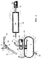
- Fig. 2 illustrates, in exploded form, the various elements described in figure 1 more detailed.
- air is added to the water 20 coming from the barrier, via a valve A, which will for example be a valve, preferably remotely controlled.
- a stop valve B also remote-controlled, allows to control the passage of water by the bypass. Air bubbles compress in section 34 before emerging in the separator 7 where it is illustrated the water level 26, the float 24 and the water outlet 33 high pressure towards the turbines then the discharge in the River.
- In 27 there is a non-return valve, accessible by a visit and maintenance gallery 25.
- the air tablet (approx. 40 kg / cm2) arrives at 28 in the tunnel storage 29, comprising a purging installation 32.
- a the other end of the tunnel is the air outlet compressed with a regulator room, pipes 31 towards the turbines and a visit gallery 30.
- the various valves can advantageously be remotely controlled.
Landscapes
- Engineering & Computer Science (AREA)
- Chemical & Material Sciences (AREA)
- Combustion & Propulsion (AREA)
- Mechanical Engineering (AREA)
- General Engineering & Computer Science (AREA)
- Other Liquid Machine Or Engine Such As Wave Power Use (AREA)
Abstract
Description
Claims (7)
- Installation hydroélectrique avec turbine à eau et turbine à air comprimé caractérisé en ce que l'air est aspiré dans une conduite forcée parcourue par de l'eau, l'eau et l'air comprimé étant séparé dans un séparateur préalablement au passage dans des turbines respectives.
- Installation hydroélectrique selon la revendication 1 caractérisé en ce que l'eau provient d'un barrage.
- Installation selon la revendication précédente caractérisée en ce que le barrage est un barrage de montagne.
- Installation hydroélectrique selon n'importe laquelle des revendications précédentes dans lequel le séparateur est logé et rendu étanche dans la roche de la montagne.
- Installation hydroélectrique selon n'importe laquelle des revendications précédentes dans lequel l'air comprimé est stocké dans au moins un réservoir logé dans la montagne préalablement au passage dans la turbine.
- Installation hydroélectrique selon n'importe laquelle des revendications précédentes dans lequel la vitesse de l'eau dans la conduite forcée est supérieure à 4 m/sec, de préférence égale ou supérieure à 6 m/sec.
- Installation selon la revendication 1 caractérisée en ce qu'elle est située au fil de l'eau.
Applications Claiming Priority (2)
| Application Number | Priority Date | Filing Date | Title |
|---|---|---|---|
| BE9900705 | 1999-10-25 | ||
| BE9900705 | 1999-10-25 |
Publications (2)
| Publication Number | Publication Date |
|---|---|
| EP1096142A2 true EP1096142A2 (fr) | 2001-05-02 |
| EP1096142A3 EP1096142A3 (fr) | 2004-04-07 |
Family
ID=3892139
Family Applications (1)
| Application Number | Title | Priority Date | Filing Date |
|---|---|---|---|
| EP00203723A Pending EP1096142A3 (fr) | 1999-10-25 | 2000-10-25 | Installation hydro-électrique avec turbine à air comprimé |
Country Status (1)
| Country | Link |
|---|---|
| EP (1) | EP1096142A3 (fr) |
Cited By (1)
| Publication number | Priority date | Publication date | Assignee | Title |
|---|---|---|---|---|
| US10001107B2 (en) | 2013-08-21 | 2018-06-19 | Paha Designs, Llc | Energy conversion system and method |
Family Cites Families (6)
| Publication number | Priority date | Publication date | Assignee | Title |
|---|---|---|---|---|
| FR1081853A (fr) * | 1953-05-07 | 1954-12-23 | Electricite De France | Procédé et dispositifs pour le réglage d'installations comprenant un compresseur hydraulique et une turbine à gaz |
| SE343106B (fr) * | 1969-06-30 | 1972-02-28 | E Janelid | |
| US4307299A (en) * | 1977-07-25 | 1981-12-22 | Norton Joseph R | System for generating electrical energy utilizing combined water power and combustible fuel sources |
| US4381645A (en) * | 1981-01-05 | 1983-05-03 | Galuska Charles W | Power unit for dam |
| EP0100799A1 (fr) * | 1982-08-13 | 1984-02-22 | Joseph Cary | Compresseur d'air hydraulique |
| JP2000014052A (ja) * | 1998-06-23 | 2000-01-14 | Mitsubishi Heavy Ind Ltd | 圧縮空気貯蔵発電設備 |
-
2000
- 2000-10-25 EP EP00203723A patent/EP1096142A3/fr active Pending
Cited By (1)
| Publication number | Priority date | Publication date | Assignee | Title |
|---|---|---|---|---|
| US10001107B2 (en) | 2013-08-21 | 2018-06-19 | Paha Designs, Llc | Energy conversion system and method |
Also Published As
| Publication number | Publication date |
|---|---|
| EP1096142A3 (fr) | 2004-04-07 |
Similar Documents
| Publication | Publication Date | Title |
|---|---|---|
| US9797107B1 (en) | Hydroelectric power generating apparatus | |
| US9617970B2 (en) | Pumped-storage power plant | |
| US8231327B2 (en) | River high pressure energy conversion machine | |
| UA69030A (en) | Wind-power accumulating apparatus | |
| CN102345549A (zh) | 浮轮式水轮机 | |
| CA2458286C (fr) | Systeme de generation d'energie | |
| FR2497877A2 (fr) | Groupe mobile, turbo-hydraulique, generateur d'electricite, immergeable | |
| EP1096142A2 (fr) | Installation hydro-électrique avec turbine à air comprimé | |
| RU2407914C1 (ru) | Способ и устройство возобновляемого получения электроэнергии и чистой воды | |
| FR3031537A1 (fr) | Systeme d'alimentation d'une turbine a partir d'une descente d'eau pluviale | |
| DE102005020257A1 (de) | Wind-Wasserkraftanlage zur Erzeugung elektrischer Energie | |
| JPH01280683A (ja) | 水力発電設備 | |
| GB2133087A (en) | Hydroelectric power plants | |
| US7287543B2 (en) | Hydraulic device | |
| JP2012145090A (ja) | 人工水路式水車発電機による発電方法と海水干満式水車発電機による発電方法と人工水路式水車発電機と海水干満式水車発電機と下掛け水車発電機用の人工水路と人工水路式灌漑用水車。 | |
| SU1742411A1 (ru) | Гидроаккумулирующий энергетический комплекс | |
| CN108385608A (zh) | 一种弯管式防波堤系统 | |
| FR2473640A1 (fr) | Installation de recuperation, accumulation hydraulique et utilisation de l'energie eolienne | |
| AU2005246994A1 (en) | A method of producing electricity from diverting flow of a natural stream | |
| KR20040002373A (ko) | 진공식 흡출관 이용 완전낙차 수력 시스템 | |
| FR2479912A1 (fr) | Dispositif capteur d'energie creee par les vagues | |
| JP2011140829A (ja) | 水力発電用導水路及び山岳部水力発電方法 | |
| RU149717U1 (ru) | Гидроэлектростанция | |
| ADDISON | PUMPING PROBLEMS-PRESENT AND FUTURE. | |
| RU61360U1 (ru) | Минигидроэлектростанция |
Legal Events
| Date | Code | Title | Description |
|---|---|---|---|
| PUAI | Public reference made under article 153(3) epc to a published international application that has entered the european phase |
Free format text: ORIGINAL CODE: 0009012 |
|
| AK | Designated contracting states |
Kind code of ref document: A2 Designated state(s): AT BE CH CY DE DK ES FI FR GB GR IE IT LI LU MC NL PT SE |
|
| AX | Request for extension of the european patent |
Free format text: AL;LT;LV;MK;RO;SI |
|
| 18D | Application deemed to be withdrawn |
Effective date: 20030503 |
|
| PUAL | Search report despatched |
Free format text: ORIGINAL CODE: 0009013 |
|
| STAA | Information on the status of an ep patent application or granted ep patent |
Free format text: STATUS: THE APPLICATION IS DEEMED TO BE WITHDRAWN |
|
| AK | Designated contracting states |
Kind code of ref document: A3 Designated state(s): AT BE CH CY DE DK ES FI FR GB GR IE IT LI LU MC NL PT SE |
|
| AX | Request for extension of the european patent |
Extension state: AL LT LV MK RO SI |
|
| D18D | Application deemed to be withdrawn (deleted) | ||
| R18D | Application deemed to be withdrawn (corrected) |
Effective date: 20030503 |