EP1096035A1 - Coated steel sheet and method and apparatus for its fabrication - Google Patents
Coated steel sheet and method and apparatus for its fabrication Download PDFInfo
- Publication number
- EP1096035A1 EP1096035A1 EP00402967A EP00402967A EP1096035A1 EP 1096035 A1 EP1096035 A1 EP 1096035A1 EP 00402967 A EP00402967 A EP 00402967A EP 00402967 A EP00402967 A EP 00402967A EP 1096035 A1 EP1096035 A1 EP 1096035A1
- Authority
- EP
- European Patent Office
- Prior art keywords
- coating
- source
- chromium
- layer
- sheet
- Prior art date
- Legal status (The legal status is an assumption and is not a legal conclusion. Google has not performed a legal analysis and makes no representation as to the accuracy of the status listed.)
- Withdrawn
Links
- 229910000831 Steel Inorganic materials 0.000 title claims abstract description 47
- 239000010959 steel Substances 0.000 title claims abstract description 47
- 238000000034 method Methods 0.000 title claims abstract description 25
- 238000004519 manufacturing process Methods 0.000 title claims abstract description 5
- VYZAMTAEIAYCRO-UHFFFAOYSA-N Chromium Chemical compound [Cr] VYZAMTAEIAYCRO-UHFFFAOYSA-N 0.000 claims abstract description 132
- 238000000576 coating method Methods 0.000 claims abstract description 111
- 239000011248 coating agent Substances 0.000 claims abstract description 97
- 238000009434 installation Methods 0.000 claims abstract description 22
- 239000011651 chromium Substances 0.000 claims description 100
- 229910052804 chromium Inorganic materials 0.000 claims description 91
- 239000011701 zinc Substances 0.000 claims description 57
- 229910052725 zinc Inorganic materials 0.000 claims description 55
- HCHKCACWOHOZIP-UHFFFAOYSA-N Zinc Chemical compound [Zn] HCHKCACWOHOZIP-UHFFFAOYSA-N 0.000 claims description 53
- 229910000599 Cr alloy Inorganic materials 0.000 claims description 39
- 238000000859 sublimation Methods 0.000 claims description 38
- 230000008022 sublimation Effects 0.000 claims description 38
- DQIPXGFHRRCVHY-UHFFFAOYSA-N chromium zinc Chemical compound [Cr].[Zn] DQIPXGFHRRCVHY-UHFFFAOYSA-N 0.000 claims description 31
- 238000001704 evaporation Methods 0.000 claims description 30
- 230000008020 evaporation Effects 0.000 claims description 29
- 239000000788 chromium alloy Substances 0.000 claims description 28
- 238000000151 deposition Methods 0.000 claims description 21
- 230000008021 deposition Effects 0.000 claims description 21
- 238000010586 diagram Methods 0.000 claims description 17
- 238000000407 epitaxy Methods 0.000 claims description 15
- 239000013078 crystal Substances 0.000 claims description 7
- 230000005855 radiation Effects 0.000 claims description 7
- 230000003247 decreasing effect Effects 0.000 claims description 6
- 229910017052 cobalt Inorganic materials 0.000 claims description 5
- 239000010941 cobalt Substances 0.000 claims description 5
- 238000004140 cleaning Methods 0.000 claims description 4
- GUTLYIVDDKVIGB-UHFFFAOYSA-N cobalt atom Chemical compound [Co] GUTLYIVDDKVIGB-UHFFFAOYSA-N 0.000 claims description 4
- 150000002500 ions Chemical class 0.000 claims description 4
- 238000009304 pastoral farming Methods 0.000 claims description 4
- 238000013519 translation Methods 0.000 claims description 4
- 238000005282 brightening Methods 0.000 claims description 3
- 230000007935 neutral effect Effects 0.000 claims description 2
- 229910045601 alloy Inorganic materials 0.000 abstract description 35
- 239000000956 alloy Substances 0.000 abstract description 35
- 229910052751 metal Inorganic materials 0.000 abstract description 20
- NDKWCCLKSWNDBG-UHFFFAOYSA-N zinc;dioxido(dioxo)chromium Chemical compound [Zn+2].[O-][Cr]([O-])(=O)=O NDKWCCLKSWNDBG-UHFFFAOYSA-N 0.000 abstract description 16
- 239000010410 layer Substances 0.000 description 145
- 239000000758 substrate Substances 0.000 description 55
- 239000002184 metal Substances 0.000 description 16
- 230000006870 function Effects 0.000 description 14
- 238000005240 physical vapour deposition Methods 0.000 description 13
- 239000007787 solid Substances 0.000 description 13
- 238000001771 vacuum deposition Methods 0.000 description 13
- 238000004458 analytical method Methods 0.000 description 10
- 238000000137 annealing Methods 0.000 description 10
- 238000005260 corrosion Methods 0.000 description 10
- 230000007797 corrosion Effects 0.000 description 10
- 238000002441 X-ray diffraction Methods 0.000 description 8
- 230000008569 process Effects 0.000 description 8
- 229920000297 Rayon Polymers 0.000 description 7
- 238000002149 energy-dispersive X-ray emission spectroscopy Methods 0.000 description 7
- 238000010438 heat treatment Methods 0.000 description 7
- 239000002964 rayon Substances 0.000 description 7
- 230000005540 biological transmission Effects 0.000 description 6
- XEEYBQQBJWHFJM-UHFFFAOYSA-N iron Substances [Fe] XEEYBQQBJWHFJM-UHFFFAOYSA-N 0.000 description 6
- 239000002344 surface layer Substances 0.000 description 6
- 238000002360 preparation method Methods 0.000 description 5
- 235000014698 Brassica juncea var multisecta Nutrition 0.000 description 4
- 241000251184 Rajiformes Species 0.000 description 4
- 240000008042 Zea mays Species 0.000 description 4
- 229910052799 carbon Inorganic materials 0.000 description 4
- 239000011247 coating layer Substances 0.000 description 4
- 235000021183 entrée Nutrition 0.000 description 4
- 238000004611 spectroscopical analysis Methods 0.000 description 4
- 230000015572 biosynthetic process Effects 0.000 description 3
- 210000004027 cell Anatomy 0.000 description 3
- 238000005520 cutting process Methods 0.000 description 3
- 230000000694 effects Effects 0.000 description 3
- 238000002003 electron diffraction Methods 0.000 description 3
- 230000003628 erosive effect Effects 0.000 description 3
- 230000006872 improvement Effects 0.000 description 3
- 238000010884 ion-beam technique Methods 0.000 description 3
- 229910052742 iron Inorganic materials 0.000 description 3
- JEIPFZHSYJVQDO-UHFFFAOYSA-N iron(III) oxide Inorganic materials O=[Fe]O[Fe]=O JEIPFZHSYJVQDO-UHFFFAOYSA-N 0.000 description 3
- 238000004020 luminiscence type Methods 0.000 description 3
- 239000000203 mixture Substances 0.000 description 3
- 238000012360 testing method Methods 0.000 description 3
- 238000011282 treatment Methods 0.000 description 3
- XKRFYHLGVUSROY-UHFFFAOYSA-N Argon Chemical compound [Ar] XKRFYHLGVUSROY-UHFFFAOYSA-N 0.000 description 2
- OKTJSMMVPCPJKN-UHFFFAOYSA-N Carbon Chemical compound [C] OKTJSMMVPCPJKN-UHFFFAOYSA-N 0.000 description 2
- 238000005275 alloying Methods 0.000 description 2
- 238000005452 bending Methods 0.000 description 2
- 238000009713 electroplating Methods 0.000 description 2
- 238000010849 ion bombardment Methods 0.000 description 2
- 238000012545 processing Methods 0.000 description 2
- 238000013112 stability test Methods 0.000 description 2
- 238000003786 synthesis reaction Methods 0.000 description 2
- 230000009466 transformation Effects 0.000 description 2
- 229910000859 α-Fe Inorganic materials 0.000 description 2
- 241001644893 Entandrophragma utile Species 0.000 description 1
- 239000002390 adhesive tape Substances 0.000 description 1
- 229910052786 argon Inorganic materials 0.000 description 1
- 230000008901 benefit Effects 0.000 description 1
- 238000005137 deposition process Methods 0.000 description 1
- 230000002542 deteriorative effect Effects 0.000 description 1
- 239000006185 dispersion Substances 0.000 description 1
- 238000004070 electrodeposition Methods 0.000 description 1
- 238000010894 electron beam technology Methods 0.000 description 1
- 229940082150 encore Drugs 0.000 description 1
- 230000002349 favourable effect Effects 0.000 description 1
- 239000007789 gas Substances 0.000 description 1
- 230000006698 induction Effects 0.000 description 1
- 239000012770 industrial material Substances 0.000 description 1
- 229910001092 metal group alloy Inorganic materials 0.000 description 1
- 150000002739 metals Chemical class 0.000 description 1
- 238000000386 microscopy Methods 0.000 description 1
- 238000003801 milling Methods 0.000 description 1
- 230000004048 modification Effects 0.000 description 1
- 238000012986 modification Methods 0.000 description 1
- 239000003973 paint Substances 0.000 description 1
- 238000009832 plasma treatment Methods 0.000 description 1
- 239000000700 radioactive tracer Substances 0.000 description 1
- 239000002356 single layer Substances 0.000 description 1
- 239000006104 solid solution Substances 0.000 description 1
- 239000000243 solution Substances 0.000 description 1
- 238000001228 spectrum Methods 0.000 description 1
- 239000007921 spray Substances 0.000 description 1
- 238000003860 storage Methods 0.000 description 1
- 239000000126 substance Substances 0.000 description 1
- 230000001131 transforming effect Effects 0.000 description 1
Images


Classifications
-
- C—CHEMISTRY; METALLURGY
- C23—COATING METALLIC MATERIAL; COATING MATERIAL WITH METALLIC MATERIAL; CHEMICAL SURFACE TREATMENT; DIFFUSION TREATMENT OF METALLIC MATERIAL; COATING BY VACUUM EVAPORATION, BY SPUTTERING, BY ION IMPLANTATION OR BY CHEMICAL VAPOUR DEPOSITION, IN GENERAL; INHIBITING CORROSION OF METALLIC MATERIAL OR INCRUSTATION IN GENERAL
- C23C—COATING METALLIC MATERIAL; COATING MATERIAL WITH METALLIC MATERIAL; SURFACE TREATMENT OF METALLIC MATERIAL BY DIFFUSION INTO THE SURFACE, BY CHEMICAL CONVERSION OR SUBSTITUTION; COATING BY VACUUM EVAPORATION, BY SPUTTERING, BY ION IMPLANTATION OR BY CHEMICAL VAPOUR DEPOSITION, IN GENERAL
- C23C14/00—Coating by vacuum evaporation, by sputtering or by ion implantation of the coating forming material
- C23C14/02—Pretreatment of the material to be coated
- C23C14/027—Graded interfaces
-
- C—CHEMISTRY; METALLURGY
- C23—COATING METALLIC MATERIAL; COATING MATERIAL WITH METALLIC MATERIAL; CHEMICAL SURFACE TREATMENT; DIFFUSION TREATMENT OF METALLIC MATERIAL; COATING BY VACUUM EVAPORATION, BY SPUTTERING, BY ION IMPLANTATION OR BY CHEMICAL VAPOUR DEPOSITION, IN GENERAL; INHIBITING CORROSION OF METALLIC MATERIAL OR INCRUSTATION IN GENERAL
- C23C—COATING METALLIC MATERIAL; COATING MATERIAL WITH METALLIC MATERIAL; SURFACE TREATMENT OF METALLIC MATERIAL BY DIFFUSION INTO THE SURFACE, BY CHEMICAL CONVERSION OR SUBSTITUTION; COATING BY VACUUM EVAPORATION, BY SPUTTERING, BY ION IMPLANTATION OR BY CHEMICAL VAPOUR DEPOSITION, IN GENERAL
- C23C14/00—Coating by vacuum evaporation, by sputtering or by ion implantation of the coating forming material
- C23C14/22—Coating by vacuum evaporation, by sputtering or by ion implantation of the coating forming material characterised by the process of coating
- C23C14/56—Apparatus specially adapted for continuous coating; Arrangements for maintaining the vacuum, e.g. vacuum locks
- C23C14/562—Apparatus specially adapted for continuous coating; Arrangements for maintaining the vacuum, e.g. vacuum locks for coating elongated substrates
-
- C—CHEMISTRY; METALLURGY
- C23—COATING METALLIC MATERIAL; COATING MATERIAL WITH METALLIC MATERIAL; CHEMICAL SURFACE TREATMENT; DIFFUSION TREATMENT OF METALLIC MATERIAL; COATING BY VACUUM EVAPORATION, BY SPUTTERING, BY ION IMPLANTATION OR BY CHEMICAL VAPOUR DEPOSITION, IN GENERAL; INHIBITING CORROSION OF METALLIC MATERIAL OR INCRUSTATION IN GENERAL
- C23C—COATING METALLIC MATERIAL; COATING MATERIAL WITH METALLIC MATERIAL; SURFACE TREATMENT OF METALLIC MATERIAL BY DIFFUSION INTO THE SURFACE, BY CHEMICAL CONVERSION OR SUBSTITUTION; COATING BY VACUUM EVAPORATION, BY SPUTTERING, BY ION IMPLANTATION OR BY CHEMICAL VAPOUR DEPOSITION, IN GENERAL
- C23C28/00—Coating for obtaining at least two superposed coatings either by methods not provided for in a single one of groups C23C2/00 - C23C26/00 or by combinations of methods provided for in subclasses C23C and C25C or C25D
- C23C28/02—Coating for obtaining at least two superposed coatings either by methods not provided for in a single one of groups C23C2/00 - C23C26/00 or by combinations of methods provided for in subclasses C23C and C25C or C25D only coatings only including layers of metallic material
- C23C28/023—Coating for obtaining at least two superposed coatings either by methods not provided for in a single one of groups C23C2/00 - C23C26/00 or by combinations of methods provided for in subclasses C23C and C25C or C25D only coatings only including layers of metallic material only coatings of metal elements only
-
- Y—GENERAL TAGGING OF NEW TECHNOLOGICAL DEVELOPMENTS; GENERAL TAGGING OF CROSS-SECTIONAL TECHNOLOGIES SPANNING OVER SEVERAL SECTIONS OF THE IPC; TECHNICAL SUBJECTS COVERED BY FORMER USPC CROSS-REFERENCE ART COLLECTIONS [XRACs] AND DIGESTS
- Y10—TECHNICAL SUBJECTS COVERED BY FORMER USPC
- Y10S—TECHNICAL SUBJECTS COVERED BY FORMER USPC CROSS-REFERENCE ART COLLECTIONS [XRACs] AND DIGESTS
- Y10S428/00—Stock material or miscellaneous articles
- Y10S428/922—Static electricity metal bleed-off metallic stock
- Y10S428/923—Physical dimension
- Y10S428/924—Composite
- Y10S428/926—Thickness of individual layer specified
-
- Y—GENERAL TAGGING OF NEW TECHNOLOGICAL DEVELOPMENTS; GENERAL TAGGING OF CROSS-SECTIONAL TECHNOLOGIES SPANNING OVER SEVERAL SECTIONS OF THE IPC; TECHNICAL SUBJECTS COVERED BY FORMER USPC CROSS-REFERENCE ART COLLECTIONS [XRACs] AND DIGESTS
- Y10—TECHNICAL SUBJECTS COVERED BY FORMER USPC
- Y10S—TECHNICAL SUBJECTS COVERED BY FORMER USPC CROSS-REFERENCE ART COLLECTIONS [XRACs] AND DIGESTS
- Y10S428/00—Stock material or miscellaneous articles
- Y10S428/922—Static electricity metal bleed-off metallic stock
- Y10S428/9335—Product by special process
- Y10S428/938—Vapor deposition or gas diffusion
-
- Y—GENERAL TAGGING OF NEW TECHNOLOGICAL DEVELOPMENTS; GENERAL TAGGING OF CROSS-SECTIONAL TECHNOLOGIES SPANNING OVER SEVERAL SECTIONS OF THE IPC; TECHNICAL SUBJECTS COVERED BY FORMER USPC CROSS-REFERENCE ART COLLECTIONS [XRACs] AND DIGESTS
- Y10—TECHNICAL SUBJECTS COVERED BY FORMER USPC
- Y10T—TECHNICAL SUBJECTS COVERED BY FORMER US CLASSIFICATION
- Y10T428/00—Stock material or miscellaneous articles
- Y10T428/12—All metal or with adjacent metals
- Y10T428/12458—All metal or with adjacent metals having composition, density, or hardness gradient
-
- Y—GENERAL TAGGING OF NEW TECHNOLOGICAL DEVELOPMENTS; GENERAL TAGGING OF CROSS-SECTIONAL TECHNOLOGIES SPANNING OVER SEVERAL SECTIONS OF THE IPC; TECHNICAL SUBJECTS COVERED BY FORMER USPC CROSS-REFERENCE ART COLLECTIONS [XRACs] AND DIGESTS
- Y10—TECHNICAL SUBJECTS COVERED BY FORMER USPC
- Y10T—TECHNICAL SUBJECTS COVERED BY FORMER US CLASSIFICATION
- Y10T428/00—Stock material or miscellaneous articles
- Y10T428/12—All metal or with adjacent metals
- Y10T428/12493—Composite; i.e., plural, adjacent, spatially distinct metal components [e.g., layers, joint, etc.]
- Y10T428/12639—Adjacent, identical composition, components
-
- Y—GENERAL TAGGING OF NEW TECHNOLOGICAL DEVELOPMENTS; GENERAL TAGGING OF CROSS-SECTIONAL TECHNOLOGIES SPANNING OVER SEVERAL SECTIONS OF THE IPC; TECHNICAL SUBJECTS COVERED BY FORMER USPC CROSS-REFERENCE ART COLLECTIONS [XRACs] AND DIGESTS
- Y10—TECHNICAL SUBJECTS COVERED BY FORMER USPC
- Y10T—TECHNICAL SUBJECTS COVERED BY FORMER US CLASSIFICATION
- Y10T428/00—Stock material or miscellaneous articles
- Y10T428/12—All metal or with adjacent metals
- Y10T428/12493—Composite; i.e., plural, adjacent, spatially distinct metal components [e.g., layers, joint, etc.]
- Y10T428/12771—Transition metal-base component
- Y10T428/12785—Group IIB metal-base component
- Y10T428/12792—Zn-base component
- Y10T428/12799—Next to Fe-base component [e.g., galvanized]
-
- Y—GENERAL TAGGING OF NEW TECHNOLOGICAL DEVELOPMENTS; GENERAL TAGGING OF CROSS-SECTIONAL TECHNOLOGIES SPANNING OVER SEVERAL SECTIONS OF THE IPC; TECHNICAL SUBJECTS COVERED BY FORMER USPC CROSS-REFERENCE ART COLLECTIONS [XRACs] AND DIGESTS
- Y10—TECHNICAL SUBJECTS COVERED BY FORMER USPC
- Y10T—TECHNICAL SUBJECTS COVERED BY FORMER US CLASSIFICATION
- Y10T428/00—Stock material or miscellaneous articles
- Y10T428/12—All metal or with adjacent metals
- Y10T428/12493—Composite; i.e., plural, adjacent, spatially distinct metal components [e.g., layers, joint, etc.]
- Y10T428/12771—Transition metal-base component
- Y10T428/12806—Refractory [Group IVB, VB, or VIB] metal-base component
- Y10T428/12826—Group VIB metal-base component
- Y10T428/12847—Cr-base component
- Y10T428/12854—Next to Co-, Fe-, or Ni-base component
Definitions
- the invention relates to steel sheets with a coating comprising a main layer of zinc-chromium alloy, the predominant phase of which is ⁇ or ⁇ .
- the invention also relates to the installation and the method for obtaining steel sheets coated with a coating of this type of alloy.
- FIG. 5 presents the diagram, drawn up by the applicant, of the summary of identification and thermal stability tests of the phases of Zn-Cr alloys as a function of the chromium content (%), in the particular case of vacuum deposition by "PVD" (Physical Vapor Deposition in language English).
- This indication therefore dissuades from using high chromium contents, greater than 30%, in particular at the interface between the steel and the coating, to avoid deteriorating adhesion.
- an alloy layer zinc-chromium does not adhere well to steel if the interface between this layer and the substrate is too rich in chromium, we have actually found that the alloy layers gradient zinc-chromium, vacuum-prepared, with a concentration of chromium of approximately 15% at the interface and approximately 5% at the surface, adhesion problems on the steel substrate; by bending a steel sheet 180 ° coated with such a layer, there is indeed a partial detachment of the alloy layer.
- the invention aims to remedy this drawback.
- the invention also relates to a method of manufacturing a sheet according to the invention from a sheet to be coated, characterized in that it comprises a step in which said coating is applied by vacuum deposition on the surface of said sheet to be coated.
- the invention also relates to installations for continuously obtaining alloy coatings, essentially comprising two metallic elements, on a sheet, and, more particularly, the Zn-Cr alloy coatings, by a vacuum deposition process of these elements, in which we scroll in continues said sheet successively in front of a source of the first element metallic alloy then in front of a source of the second alloying element metallic.
- source in this text can designate a source of evaporation, or a source of sublimation which can be heated by bombardment electronics, conduction (resistance or induction), radiation or plasma.
- the vapor flow emitted by the metallic source is strong (> 1g / mn.cm 2 )
- the pressure gradient of the metallic vapor above the source is strong, a large majority of the metallic atoms which will leave the source will undergo several collisions before reaching the substrate.
- the dispersion of the metallic element on the substrate will be all the greater the higher the vapor flow rate.
- the alloy layer obtained is not homogeneous in composition in depth: richer in element A near the substrate than in surface, richer in element B on the surface than near the substrate; layer of alloy obtained is qualified as a “gradient” layer.
- Document JP 03-191053 discloses a ZnCr coating gradient on a steel sheet, in which the chromium concentration at the interface with the substrate is greater than 10% while it is less than 5% in external surface; such a coating provides both resistance significant in corrosion due to the high chromium concentration in the depth and good phosphating ability due to the low surface chromium concentration.
- the useful solid emission angle of a source is generally delimited by this window; it brings together the possible trajectories of elements likely to condense on the substrate.
- sources A and B are placed in the same chamber of so as to transmit through the same window; if sources A and B are arranged at the same distance from this window, the useful angle of emission of each element is identical.
- the window through which source A and source B emit have two edges; these edges are adjustable in position (either in height and / or laterally), and thus form diaphragms; the edge which is located from side of source A is called “input edge A” and the edge which is located on the side of source B is called “output edge B”.
- the entry edge A is placed at a distance h x from the strip running path (and not close to it), at the entry of the deposition zone a'a ", it mainly deposit the element B, and we will obtain a double-layer coating of type -B (+ A) -AB, where the sublayer B (+ A) will have an A content which will mainly depend on the vapor flow rate of the source and the residual pressure in the deposition chamber, and where the layer AB is richer in element A on the side of the substrate than on the surface.
- the exit edge B is placed at a distance h y from the strip running path (and not close to it), at the exit from the deposition zone b'b ", it will deposit mainly element A, and we will obtain a two-layer coating of type -AB-A (+ B) (or more simply -AB-A), where layer A (+ B) will have a B content which will be a function mainly from the source vapor flow and the residual pressure in the deposition chamber, and where the AB sublayer is richer in element A on the substrate side than at the surface.
- edges A and / or B which consists in putting them at a distance h x and / or h y from the sheet travel path, is to widen the two useful solid angles of transmission of element A and element B;
- the distance h x from the input edge A further widens the useful angle of emission of element B whose source is more distant, than that of element A, whose source is closer, and therefore leads to forming an element layer B under the alloy layer AB;
- the distance h y from the output edge B further widens the useful angle of emission of element A whose source is more distant, than that of element B, whose source is closer, and therefore leads to the forming an element layer A on the alloy layer AB;
- the distancing of an edge further widens the useful angle of emission of element from which the source is the most distant and therefore leads to the formation of a pure layer (or in the majority of cases, low alloy) of this element above or below the AB alloy layer; the effect is all the more pronounced the
- the object of the invention is to produce, in addition to the coatings offered by the document JP 06 212410 A, coatings of type A-AB-A or B-AB-B, where the layer AB is always richer in element A on the substrate side than in surface if the strip travels from source A to source B.
- said means for decrease the emission angle are formed by a vertical movable screen arranged between element source A and element source B.
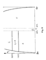
- Figure 4 illustrates, without limitation, such an installation, which will described more precisely later in the particular case of a coating comprising a main layer of zinc-chrome alloy.
- the installation can obviously be used to coat continuous strips of sheets.
- these different variants can be obtained by varying the position of this screen between element source A and element source B or by using two screens.
- partial epitaxy junction we mean that at the interface between the substrate and the underlying layer of this alloy in cubic form centered there is continuity between some of the ferrite crystals of the steel at this interface and some of the centered cubic crystals of the Zn-Cr alloy at this same interface.
- a means to verify that the junction between the steel and this layer intercalated presents a partial epitaxy character consists in carrying out a electron diffraction diagram on thin plates obtained by cross-sections in the plane of the interposed layer, in the vicinity of the interface with steel.
- Figure 6 illustrates the diagram obtained when the junction has a epitaxy character: we observe that the diffraction rings form broken lines and are not complete, indicating that the orientation of centered cubic grains of the layer inserted in the cutting plane is not random and that there is a partial epitaxy relationship with the grains located below the cutting plane, ie with the steel grains; Moreover, the angle between the maximum intensity position of the ring which corresponds to ⁇ 011 ⁇ crystallographic planes of the ⁇ -ZnCr phase and that of the ⁇ 200 ⁇ planes is 90 °, which indicates a growth texture of type [011].
- the underlying layer according to the invention could significantly improve the adhesion of the coating to provided that its thickness exceeds 0.01 ⁇ m; very good results have been obtained with a thickness of approximately 0.02 ⁇ m; like phase ⁇ present a fragile character, it should be avoided that this layer is too thick, to avoid problems when forming the coated sheet; thus, preferably the thickness of this layer is less than 1 ⁇ m.
- the invention is used in particular to improve the adhesion of layers Gradient Zn-Cr, with higher chromium content at depth only on the surface, as described in the document JP 03-191053 already cited.
- a variant of the invention consists in subjecting the sheet obtained to a heat treatment so as to transform, at least in part, phase ⁇ of the main layer of the coating in phase ⁇ , as described for example in document JP 08-013192 which indicates that such processing allows to improve the resistance to red rust of the sheet.
- a vacuum deposition process preferably a vacuum deposition process; indeed, this type of process allows to more easily control the proportions of chromium and zinc, which are coating thickness variables: higher chromium content at neighborhood of the steel to form the intermediate adhesion layer according to the invention, lower chromium content in the vicinity of the surface.
- this variant which aims to obtain a coating whose main layer is transformed, at least partially, into phase ⁇ , we preferably heats the sheet to be coated between 170 ° C and 230 ° C; by heating the substrate in the range 170 to 200 ° C approximately, coatings are achieved whose main layer is two-phase, for which the height of the line (131) of the ⁇ -Zncr phase is between 10 and 100% approximately of the height of the line (0002) of the phase ⁇ -ZnCr.
- An advantage of this variant of the invention is that further processing of the type used for baking a coat of paint is sufficient to complete the transformation of a sufficient quantity of phase ⁇ into phase ⁇ to obtain the best resistance to corrosion; it is therefore no longer necessary perform a specific subsequent heat treatment to obtain improving corrosion resistance.
- phase ⁇ is predominant in the coating, we observes a significant improvement in the protection against corrosion provided by this coating compared to the coating of the same thickness and the same composition, but the predominant phase of which is phase ⁇ ; this improvement would come, at least in part, from the microcrystalline structure obtained by heating the substrate during and / or after coating; indeed, the that no grain boundaries pass directly through the layer from start to finish share as in the case of columnar morphology could explain marked improvement in corrosion resistance.
- the underlying adhesion layer according to the invention is particularly advantageous, because even when deposited on a heated substrate and / or case of subsequent heat treatments, phase la of this underlying layer is very stable in temperature and continues to provide the specific effect of the invention to improve the adhesion of the coating, even after transformation of phase ⁇ into phase ⁇ .
- the partial junction by epitaxy between the steel and deposition it is important to start from a clean and reactive steel surface, as that obtained directly from a continuous annealing line carried out under a reducing atmosphere.
- the surface is not clean and reactive enough, it is important to perform a preliminary cleaning and brightening operation in conditions for obtaining, according to the invention, the partial junction by epitaxy between steel and deposition.
- the necessary bombardment density preferably exceeds 10 16 ions / cm 2 of surface to be cleaned.
- the conditions for cleaning and brightening the surface are adapted in a manner known per se to obtain such a clean surface and reactive only at the annealing outlet, for example according to the method described in FR 2 757 880 (SOLLAC) as a function of the luminescence intensity of at least one tracer element of the surface to be coated.
- the vacuum deposition installation comprises means for scrolling sheet metal or a strip of sheet metal, a chamber of evaporation and / or sublimation open on an evaporation and / or window sublimation leading to an area of the sheet metal running path.
- the entry edge 3 defines the right limit 5 of the angle emission solid from crucible 1 of chromium and the output edge 4 defines the left limit 6 of the solid angle of emission from the crucible 2 of zinc.
- the entry edge 3 would also define the right limit of the solid angle of emission from crucible 2 of zinc; the edge output 4 defines the left limit 7 of the solid angle of emission from the chromium crucible 1.
- Such a coating poses adhesion problems, that the presence of the underlying layer of zinc or zinc-chromium alloy rich in zinc worsens, that the invention aims to solve.
- the left limit 7 of the solid angle of emission from the crucible 1 of chrome is always defined by the exit edge 4 of the window evaporation or sublimation and is not affected by the mobile vertical screen 9.
- this screen 9 thus positioned according to the invention, it exists in the window an area through which elements essentially pass "Chrome” so as to form, on the other side of the window on the sheet metal scrolling, a zone 11 on which mainly condenses chrome elements.
- the thickness of the coating and, therefore, of each layer, is obviously proportional to the sheet speed and the evaporation rate or sublimation.
- the pressure in the coating installation is of the order of 10 -3 Pa; at this pressure, the average free path of the evaporated or sublimed atoms is greater than 50 cm, which makes it possible to consider that the major part of the atoms leaving the crucibles in the direction of the evaporation or sublimation window do not undergo collisions and spread in straight lines.
- the coating may include such surface layer, especially if you move the exit edge 4 away from the area 13.
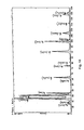
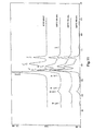
- the glow discharge spectra clearly show the increase in the concentration and the decrease of that of chromium in the main layer of the coating, which shows that this main layer of Zn-Cr alloy is indeed "gradient"; the increased signal from zinc on the surface does not reflect not a higher concentration of zinc but is only an artifact related to the analysis method, zinc having a spray coefficient four times higher than that of chromium.
- the “EDX” analysis shows a general profile of decrease in chromium concentration in the main coating layer up to 5% approximately by weight in the vicinity of the surface; this analysis reveals the presence of the underlying layer of zinc-chromium alloy according to the invention, much richer in chromium (more than 34% by weight) than the main layer at neighborhood of this substrate, the chromium concentration of which does not exceed 30% with reference to the previous analyzes.
- the Zn-Cr alloy of the main layer of the coating is almost entirely composed of the hexagonal phase ⁇ .
- Figure 12 illustrates the X-ray diffraction patterns obtained under grazing incidence, zones A (curve A), B (curve B) and C (curve C); we find the majority phase ⁇ on curve A and on curve B, which confirms the structure of the main coating layer; we detect the phase ⁇ on curve C (at level 2 ⁇ ⁇ 50,000), which confirms the structure of the underlying adhesion layer according to the invention; we even detect the trace of phase ⁇ on curve B.
- annealing is carried out at 225 ° C. for 1 hour, so as to transform the structure of the main layer of this coating into a structure ⁇
- FIG. 6 illustrates the diagram obtained: it is observed that the rings of diffraction form broken lines and are not complete, which indicates that the orientation of the grains of phase ⁇ of the underlying layer is not random and there is a partial epitaxy relationship with the grains located below the cutting plane, i.e. with the steel grains of the substrate.
- the coating has the same layer main zinc-chromium alloy previously described: thickness 4.5 ⁇ m approximately, gradient, phase ⁇ .
- the adhesion test of the following coating is carried out: the sample is folded at 180 °, an Scotch TM type adhesive tape is applied to the bending zone, the tape applied is torn off, then observed on the surface of the sample if the coating is intact or partially removed or completely removed.
- the sublayer according to the invention having a partial epitaxy relationship with the steel substrate significantly improves coating adhesion based on zinc-chromium alloy.
Landscapes
- Chemical & Material Sciences (AREA)
- Chemical Kinetics & Catalysis (AREA)
- Engineering & Computer Science (AREA)
- Materials Engineering (AREA)
- Mechanical Engineering (AREA)
- Metallurgy (AREA)
- Organic Chemistry (AREA)
- Physical Vapour Deposition (AREA)
- Electroplating Methods And Accessories (AREA)
- Laminated Bodies (AREA)
Abstract
Description
L'invention concerne les tôles d'acier dotées d'un revêtement comprenant une couche principale d'alliage zinc-chrome, dont la phase prépondérante est δ ou ζ.The invention relates to steel sheets with a coating comprising a main layer of zinc-chromium alloy, the predominant phase of which is δ or ζ.
L'invention concerne également l'installation et le procédé d'obtention de tôles d'acier revêtues d'un revêtement de ce type d'alliage.The invention also relates to the installation and the method for obtaining steel sheets coated with a coating of this type of alloy.
Le document EP 0 607 452 (KAWASAKI) décrit les phases cristallines que l'on peut obtenir en déposant par électrodéposition des revêtements monocouche d'alliages Zn-Cr et les principales propriétés associées à ces phases ; selon les proportions respectives de zinc et de chrome, selon les conditions d'électrodéposition, on distingue ainsi les principales phases suivantes d'alliage :
- η de structure hexagonale identique à celle du zinc pur, où le chrome est en solution solide en faibles proportions ;
- δ également de structure hexagonale dont le paramètre de maille a est supérieur à celui de la structure η, dont le paramètre de maille c est inférieur à celui de la structure η ;
- Γ de structure cubique centré dont le paramètre de maille est supérieur à celui du chrome pur.
- η with a hexagonal structure identical to that of pure zinc, where chromium is in solid solution in small proportions;
- δ also of hexagonal structure whose mesh parameter a is greater than that of the structure η, whose mesh parameter c is less than that of the structure η;
- Γ of centered cubic structure with a mesh parameter greater than that of pure chromium.
Le document JP 08-013192 A (KAWASAKI) enseigne que le recuit d'une couche d'alliage zinc-chrome dont la phase est δ transforme la structure de cette couche ; dans des conditions de traitement qui varient selon le taux de chrome, la durée et la température du recuit (130°C à 200°C), on obtient ainsi une phase :
- ζ de structure monoclinique.
- ζ of monoclinic structure.
La figure 5 présente le diagramme, établi par la demanderesse, de la synthèse des essais d'identification et de stabilité thermique des phases des alliages Zn-Cr en fonction de la teneur en chrome (%), dans le cas particulier de dépôts réalisés sous vide par « PVD » (Physical Vapor Deposition en langue anglaise).FIG. 5 presents the diagram, drawn up by the applicant, of the summary of identification and thermal stability tests of the phases of Zn-Cr alloys as a function of the chromium content (%), in the particular case of vacuum deposition by "PVD" (Physical Vapor Deposition in language English).
A la page 9, lignes 57-58 du document EP 0 607 452, on indique qu'en
deçà de 5% de teneur pondérale en chrome dans l'alliage, on ne formera pas
de phase Γ dans le revêtement, et que au delà de 30% de chrome, le
revêtement obtenu ne présente pas une bonne adhérence sur l'acier.On
Cette indication dissuade donc d'utiliser des teneurs élevées en chrome, supérieures à 30%, notamment à l'interface entre l'acier et le revêtement, pour éviter de détériorer l'adhérence.This indication therefore dissuades from using high chromium contents, greater than 30%, in particular at the interface between the steel and the coating, to avoid deteriorating adhesion.
Conformément à cette divulgation selon laquelle une couche d'alliage zinc-chrome adhère mal à l'acier si l'interface entre cette couche et le substrat est trop riche en chrome, on a effectivement constaté que les couches d'alliage zinc-chrome à gradient, préparées sous vide, présentant une concentration en chrome de 15% environ à l'interface et de 5% environ en surface, posaient des problèmes d'adhérence sur le substrat d'acier ; en pliant à 180° une tôle d'acier revêtue d'une telle couche, on observe en effet un décollement partiel de la couche d'alliage.According to this disclosure that an alloy layer zinc-chromium does not adhere well to steel if the interface between this layer and the substrate is too rich in chromium, we have actually found that the alloy layers gradient zinc-chromium, vacuum-prepared, with a concentration of chromium of approximately 15% at the interface and approximately 5% at the surface, adhesion problems on the steel substrate; by bending a steel sheet 180 ° coated with such a layer, there is indeed a partial detachment of the alloy layer.
L'invention a pour but de remédier à cet inconvénient.The invention aims to remedy this drawback.
A cet effet l'invention a pour objet une tôle d'acier dotée d'un revêtement comprenant une couche principale d'alliage zinc-chrome, dont la phase prépondérante présente une structure δ et/ou ζ, caractérisée en ce que ledit revêtement comprend également une couche sous-jacente d'adhérence en alliage zinc-chrome, intercalée entre l'acier de la tôle et ladite couche principale, qui présente :
- une structure cristalline cubique centré de type Γ,
- une teneur pondérale en chrome suffisamment élevée pour obtenir ladite structure Γ,
- une jonction au moins partielle d'épitaxie avec ledit acier, manifestée par la présence d'anneaux incomplets sur un diagramme de diffraction électronique de ladite sous-couche réalisé sur des coupes pratiquées au voisinage de l'interface avec l'acier, parallèlement à cette interface.
- a centered cubic crystal structure of type Γ,
- a chromium content by weight sufficiently high to obtain said structure Γ,
- an at least partial junction of epitaxy with said steel, manifested by the presence of incomplete rings on an electronic diffraction diagram of said underlayer produced on sections made in the vicinity of the interface with steel, parallel to this interface.
L'invention peut également présenter une ou plusieurs des caractéristiques suivantes :
- la teneur pondérale en chrome dans ladite couche sous-jacente est comprise entre 30 et 70%.
- l'épaisseur de ladite couche sous-jacente est comprise entre 0,01 µm et 1 µm.
- l'épaisseur de ladite couche principale est supérieure à 1 µm ; en effet, la rugosité du substrat est souvent de l'ordre de 1 µm et parfois supérieure ; pour que le revêtement apporte une protection efficace contre la corrosion et une bonne résistance à la rouille rouge, il importe que le revêtement soit suffisamment couvrant et que son épaisseur soit supérieure à la rugosité du substrat.
- ladite couche principale est une couche à gradient de concentration de chrome; de préférence, la variation de concentration de chrome dans l'épaisseur de ladite couche principale est supérieure ou égale à 10% en poids.
- the chromium content by weight in said underlying layer is between 30 and 70%.
- the thickness of said underlying layer is between 0.01 μm and 1 μm.
- the thickness of said main layer is greater than 1 μm; in fact, the roughness of the substrate is often of the order of 1 μm and sometimes higher; for the coating to provide effective corrosion protection and good resistance to red rust, it is important that the coating is sufficiently covering and that its thickness is greater than the roughness of the substrate.
- said main layer is a chromium concentration gradient layer; preferably, the variation of chromium concentration in the thickness of said main layer is greater than or equal to 10% by weight.
La concentration de chrome dans ladite couche principale peut être plus élevée au voisinage de la surface qu'au voisinage de l'acier ; de préférence, afin d'obtenir à la fois une protection efficace contre la corrosion et une bonne phosphatabilité, la concentration de chrome dans ladite couche principale est plus élevée au voisinage de l'acier qu'au voisinage de la surface.
- la phase prépondérante de la couche principale présente une structure ζ.
- la couche principale du revêtement peut ne présenter que partiellement une structure ζ ; notamment, si on soumet le revêtement à un rayonnement X sous incidence rasante de l'ordre de 3°, ledit rayonnement provenant d'un tube à rayons X à anti-cathode de cobalt alimenté sous 30kV et débitant 30mA, émettant une raie de longueur d'onde Ka = 0,179026 nm, et si l'on analyse la diffraction de ce rayonnement à l'aide d'un monochromateur arrière et d'un détecteur à scintillations, la hauteur de la raie de diffraction (131) de la phase ζ-ZnCr reste comprise entre 10% et 100% environ de la hauteur de la raie (0002) de la phase δ-ZnCr.
- the preponderant phase of the main layer has a structure ζ.
- the main layer of the coating may only partially have a structure ζ; in particular, if the coating is subjected to X-ray radiation at a grazing incidence of the order of 3 °, said radiation coming from an X-ray tube with cobalt anti-cathode supplied at 30kV and delivering 30mA, emitting a line of length Ka = 0.179026 nm, and if we analyze the diffraction of this radiation using a rear monochromator and a scintillation detector, the height of the diffraction line (131) of the phase ζ-ZnCr remains between approximately 10% and 100% of the height of the line (0002) of phase δ-ZnCr.
L'invention a également pour objet un procédé de fabrication d'une tôle selon l'invention à partir d'une tôle à revêtir, caractérisé en ce qu'il comprend une étape dans laquelle ledit revêtement est appliqué par dépôt sous vide sur la surface de ladite tôle à revêtir.The invention also relates to a method of manufacturing a sheet according to the invention from a sheet to be coated, characterized in that it comprises a step in which said coating is applied by vacuum deposition on the surface of said sheet to be coated.
L'invention peut également présenter une ou plusieurs des caractéristiques suivantes :
- ledit revêtement est appliqué par évaporation et/ou sublimation sous vide de zinc et de chrome.
- ladite tôle à revêtir est portée pendant le dépôt à une température comprise entre 170°C et 230°C environ.
- immédiatement avant l'étape de dépôt, on nettoie et/ou on avive ladite surface d'une manière adaptée pour obtenir ladite jonction au moins partielle d'épitaxie, de préférence par bombardement d'ions de gaz neutre.
- said coating is applied by evaporation and / or sublimation under vacuum of zinc and chromium.
- said sheet to be coated is brought during deposition to a temperature of between 170 ° C and 230 ° C approximately.
- immediately before the deposition step, said surface is cleaned and / or brightened in a manner suitable for obtaining said at least partial epitaxy junction, preferably by bombardment of neutral gas ions.
L'invention concerne également les installations d'obtention en continu de revêtements d'alliages, comportant essentiellement deux éléments métalliques, sur une tôle, et, plus particulièrement, les revêtements d'alliage Zn-Cr, par un procédé de dépôt sous vide de ces éléments, dans laquelle on fait défiler en continu ladite tôle successivement devant une source du premier élément métallique d'alliage puis devant une source du second élément d'alliage métallique.The invention also relates to installations for continuously obtaining alloy coatings, essentially comprising two metallic elements, on a sheet, and, more particularly, the Zn-Cr alloy coatings, by a vacuum deposition process of these elements, in which we scroll in continues said sheet successively in front of a source of the first element metallic alloy then in front of a source of the second alloying element metallic.
Le mot « source » dans ce texte peut désigner une source d'évaporation, ou un source de sublimation qui peut être chauffée par bombardement électronique, conduction (résistance ou induction), radiation ou par plasma .The word "source" in this text can designate a source of evaporation, or a source of sublimation which can be heated by bombardment electronics, conduction (resistance or induction), radiation or plasma.
Dans un tel procédé, lorsque le débit de vapeur émis par la source métallique est faible (< 1g/mn.cm2), le gradient de pression de la vapeur métallique au dessus de la source est faible, les atomes métalliques évaporés ou sublimés subissent de ce fait très peu de collisions. On peut donc considérer que la propagation de la grande majorité des atomes entre la source et le substrat s'effectue en ligne droite.In such a process, when the vapor flow emitted by the metal source is low (<1g / mn.cm 2 ), the pressure gradient of the metal vapor above the source is low, the evaporated or sublimated metal atoms undergo therefore very few collisions. We can therefore consider that the propagation of the vast majority of atoms between the source and the substrate takes place in a straight line.
En revanche, si le débit de vapeur émis par la source métallique est fort (> 1g/mn.cm2), le gradient de pression de la vapeur métallique au dessus de la source est fort, une grande majorité des atomes métalliques qui vont quitter la source vont subir plusieurs collisions avant d'atteindre le substrat. La dispersion de l'élément métallique sur le substrat sera d'autant plus importante que le débit de vapeur est fort.On the other hand, if the vapor flow emitted by the metallic source is strong (> 1g / mn.cm 2 ), the pressure gradient of the metallic vapor above the source is strong, a large majority of the metallic atoms which will leave the source will undergo several collisions before reaching the substrate. The dispersion of the metallic element on the substrate will be all the greater the higher the vapor flow rate.
On sait, qu'en disposant un écran entre la source et le substrat vu de cette source sous un angle solide donné, une partie de la vapeur émise dans cette angle solide est arrêtée par cet écran et ne se condense plus sur le substrat. Si le débit de vapeur est faible et si la pression résiduelle dans la chambre de dépôts est faible, comprise entre 10-4 et 10-1 Pa, c'est la quasi-totalité de la vapeur qui sera arrêtée.It is known that by having a screen between the source and the substrate seen from this source at a given solid angle, part of the vapor emitted in this solid angle is stopped by this screen and no longer condenses on the substrate. If the steam flow is low and if the residual pressure in the deposit chamber is low, between 10 -4 and 10 -1 Pa, almost all of the steam will be stopped.
Lorsqu'une bande à revêtir défile successivement devant une source d'évaporation ou de sublimation d'un premier élément d'alliage A puis devant une source d'évaporation ou de sublimation d'un second élément d'alliage B, tel que décrit par exemple dans le document JP 06 212410 A (ISHIKAWAJIMA HARIMA HEAVY IND Ltd), la couche d'alliage obtenue n'est pas homogène en composition dans la profondeur : plus riche en élément A près du substrat qu'en surface, plus riche en élément B en surface que près du substrat ; la couche d'alliage obtenue est qualifiée de couche « à gradient ».When a strip to be coated passes successively in front of a source evaporation or sublimation of a first element of alloy A then in front a source of evaporation or sublimation of a second element of alloy B, such as described for example in the document JP 06 212410 A (ISHIKAWAJIMA HARIMA HEAVY IND Ltd), the alloy layer obtained is not homogeneous in composition in depth: richer in element A near the substrate than in surface, richer in element B on the surface than near the substrate; layer of alloy obtained is qualified as a “gradient” layer.
Le document JP 03-191053 (KOBE STEEL) divulgue un revêtement ZnCr à gradient sur une tôle d'acier, dans lequel la concentration en chrome à l'interface avec le substrat est supérieure à 10% alors qu'elle est inférieure à 5% en surface externe ; un tel revêtement apporte à la fois une résistance importante à la corrosion grâce à la concentration élevée en chrome dans la profondeur et une bonne aptitude à la phosphatation grâce à la faible concentration en chrome en surface.Document JP 03-191053 (KOBE STEEL) discloses a ZnCr coating gradient on a steel sheet, in which the chromium concentration at the interface with the substrate is greater than 10% while it is less than 5% in external surface; such a coating provides both resistance significant in corrosion due to the high chromium concentration in the depth and good phosphating ability due to the low surface chromium concentration.
Pour obtenir un tel revêtement ZnCr à gradient à l'aide du procédé précité, plus riche en chrome du côté du substrat qu'en surface, il convient de faire défiler la bande à revêtir d'abord devant la source de chrome, puis devant la source de zinc ; de manière générale, pour obtenir un revêtement d'alliage AB à gradient, plus riche en élément A du côté du substrat qu'en surface, il convient de faire défiler le substrat d'abord devant la source A, puis devant la source B.To obtain such a ZnCr gradient coating using the above method, richer in chromium on the substrate side than on the surface, it should be run the strip to be coated first in front of the chrome source, then in front of the source of zinc; in general, to obtain an AB alloy coating with gradient, richer in element A on the substrate side than at the surface, it is advisable to scroll the substrate first in front of source A, then in front of source B.
Les installations de dépôt sous vide comportent :
- des moyens de défilement de tôle ou d'une bande de tôle,
- une chambre d'évaporation et/ou de sublimation ouverte sur une fenêtre d'évaporation et/ou de sublimation débouchant sur une zone du chemin de défilement de la tôle,
- au moins une source d'éléments à déposer disposée dans cette chambre de manière à émettre au travers de la fenêtre.
- sheet metal scrolling means or a sheet metal strip,
- an evaporation and / or sublimation chamber open onto an evaporation and / or sublimation window opening onto an area of the sheet metal running path,
- at least one source of elements to be deposited arranged in this room so as to emit through the window.
L'angle solide utile d'émission d'une source est en général délimité par cette fenêtre ; il rassemble les trajectoires possibles d'éléments susceptibles de se condenser sur le substrat.The useful solid emission angle of a source is generally delimited by this window; it brings together the possible trajectories of elements likely to condense on the substrate.
Dans les installations de dépôt comprenant une source d'élément A et une source d'élément B pour la réalisation d'un revêtement comprenant une couche d'alliage AB, les sources A et B sont disposées dans la même chambre de manière à émettre au travers de la même fenêtre ; si les sources A et B sont disposées à la même distance de cette fenêtre, l'angle utile d'émission de chaque élément est identique.In disposal facilities comprising an A source and an source of element B for producing a coating comprising a layer of alloy AB, sources A and B are placed in the same chamber of so as to transmit through the same window; if sources A and B are arranged at the same distance from this window, the useful angle of emission of each element is identical.
Dans le cas des installations adaptées pour la réalisation de couches à
gradient où la bande à revêtir défile successivement d'abord devant une source
A puis devant une source B émettant au travers de la même fenêtre, le
document JP 06 212410 A déjà cité décrit l'utilisation d'écrans, « caches » ou
« diaphragmes » pour obtenir des revêtements multicouches comprenant une
couche d'alliage AB à gradient et une couche d'élément A pur et/ou une couche
d'éléments B pur.In the case of installations suitable for the production of
gradient where the strip to be coated successively scrolls first in front of a source
A then in front of a source B emitting through the same window, the
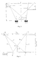
On va maintenant décrire des procédés d'obtention de tels revêtements multicouches à l'aide de ces installations en se référant aux figures 1 à 3 ; la flèche x indique le sens de défilement du substrat à revêtir.We will now describe methods for obtaining such coatings multilayer using these facilities with reference to Figures 1 to 3; the arrow x indicates the direction of travel of the substrate to be coated.
La fenêtre au travers de laquelle la source A et la source B émettent présentent deux bords ; ces bords sont réglables en position (soit en hauteur et/ou latéralement), et forment ainsi des diaphragmes ; le bord qui est situé du côté de la source A est appelé « bord d'entrée A » et le bord qui est situé du côté de la source B est appelé « bord de sortie B ».The window through which source A and source B emit have two edges; these edges are adjustable in position (either in height and / or laterally), and thus form diaphragms; the edge which is located from side of source A is called "input edge A" and the edge which is located on the side of source B is called "output edge B".
En se référant à la figure 2, si le bord d'entrée A est disposé à distance hx du chemin de défilement de la bande (et non pas à proximité), en entrée de la zone de dépôt a'a", il se déposera majoritairement l'élément B, et on obtiendra un revêtement bicouche de type -B(+A)-AB, où la sous-couche B(+A) aura une teneur en A qui sera fonction principalement du débit de vapeur de la source et de la pression résiduelle dans la chambre de dépôts, et où la couche AB est plus riche en élément A du côté du substrat qu'en surface. Dans un souci de simplification, on parlera ultérieurement de revêtement -B-AB pour décrire un revêtement de type -B(+A)-AB.Referring to FIG. 2, if the entry edge A is placed at a distance h x from the strip running path (and not close to it), at the entry of the deposition zone a'a ", it mainly deposit the element B, and we will obtain a double-layer coating of type -B (+ A) -AB, where the sublayer B (+ A) will have an A content which will mainly depend on the vapor flow rate of the source and the residual pressure in the deposition chamber, and where the layer AB is richer in element A on the side of the substrate than on the surface. For the sake of simplification, we will speak later of coating -B-AB to describe a coating of type -B (+ A) -AB.
Si l'on inverse le sens de défilement de la bande, on obtient alors un revêtement bicouche de type -AB-B(+A), où la sous-couche AB est plus riche en élément B du côté du substrat qu'en surface.If we reverse the direction of travel of the strip, we obtain a two-layer coating of type -AB-B (+ A), where the AB sublayer is richer as element B on the substrate side as on the surface.
En se référant à la figure 1, si le bord de sortie B est disposé à distance hy du chemin de défilement de la bande (et non pas à proximité), en sortie de la zone de dépôt b'b", il se déposera majoritairement l'élément A, et on obtiendra un revêtement bi-couche de type -AB-A(+B) (ou plus simplement -AB-A), où la couche A(+B) aura une teneur en B qui sera fonction principalement du débit de vapeur de la source et de la pression résiduelle dans la chambre de dépôts, et où la sous-couche AB est plus riche en élément A du côté du substrat qu'en surface.Referring to FIG. 1, if the exit edge B is placed at a distance h y from the strip running path (and not close to it), at the exit from the deposition zone b'b ", it will deposit mainly element A, and we will obtain a two-layer coating of type -AB-A (+ B) (or more simply -AB-A), where layer A (+ B) will have a B content which will be a function mainly from the source vapor flow and the residual pressure in the deposition chamber, and where the AB sublayer is richer in element A on the substrate side than at the surface.
Si l'on inverse le sens de défilement de la bande, on obtient alors un revêtement bicouche de type -B(+A)-AB, où la couche AB est plus riche en élément B du côté du substrat qu'en surface.If we reverse the direction of travel of the strip, we obtain a double-layer coating of type -B (+ A) -AB, where the layer AB is richer in element B on the substrate side only on the surface.
On voit donc, que dans le sens de défilement de la bande tel qu'indiqué aux figures 1 et 2, une telle disposition des bords de la fenêtre utile d'émission des éléments A et B permet de réaliser des revêtements bi-couches de type -B- AB, -AB-A ; en associant les deux dispositions de bords A et B comme illustré à la figure 3, on obtient des revêtements -B-AB-A, où la couche AB est toujours plus riche en élément A du côté du substrat qu'en surface.We therefore see that in the direction of travel of the strip as indicated in Figures 1 and 2, such an arrangement of the edges of the useful transmission window elements A and B allows for two-layer coatings of type -B- AB, -AB-A; by combining the two edge arrangements A and B as illustrated in Figure 3, we obtain coatings -B-AB-A, where the layer AB is always richer in element A on the substrate side than at the surface.
L'effet direct d'une telle disposition des bords A et/ou B, qui consiste à les mettre à distance hx et/ou hy du chemin de défilement de la tôle, est d'élargir les deux angles solides utiles d'émission d'élément A et d'élément B ; la mise à distance hx du bord d'entrée A élargit davantage l'angle utile d'émission d'élément B dont la source est plus éloignée, que celui d'élément A, dont la source est plus proche, et conduit donc à la formation d'une couche d'élément B sous la couche d'alliage AB ; la mise à distance hy du bord de sortie B élargit davantage l'angle utile d'émission d'élément A dont la source est plus éloignée, que celui d'élément B, dont la source est plus proche, et conduit donc à la formation d'une couche d'élément A sur la couche d'alliage AB ; de manière générale, la mise à distance d'un bord élargit davantage l'angle utile d'émission d'élément dont la source est la plus éloignée et conduit donc à la formation d'une couche pure (ou dans la majorité des cas, peu allié) de cet élément au dessus ou en dessous de la couche d'alliage AB ; l'effet est d'autant plus prononcé que la distance entre les sources est importante.The direct effect of such an arrangement of edges A and / or B, which consists in putting them at a distance h x and / or h y from the sheet travel path, is to widen the two useful solid angles of transmission of element A and element B; the distance h x from the input edge A further widens the useful angle of emission of element B whose source is more distant, than that of element A, whose source is closer, and therefore leads to forming an element layer B under the alloy layer AB; the distance h y from the output edge B further widens the useful angle of emission of element A whose source is more distant, than that of element B, whose source is closer, and therefore leads to the forming an element layer A on the alloy layer AB; in general, the distancing of an edge further widens the useful angle of emission of element from which the source is the most distant and therefore leads to the formation of a pure layer (or in the majority of cases, low alloy) of this element above or below the AB alloy layer; the effect is all the more pronounced the greater the distance between the sources.
L'invention a pour but de réaliser, outre les revêtements proposés par le
document JP 06 212410 A, des revêtements de type A-AB-A ou B-AB-B, où la
couche AB est toujours plus riche en élément A du côté du substrat qu'en
surface si la bande défile de la source A vers la source B.The object of the invention is to produce, in addition to the coatings offered by the
Bien évidemment si le sens de la bande est inversée, on peut obtenir les mêmes types de revêtements que précédemment, mais dans ce cas la couche AB devient plus riche en élément B du côté du substrat qu'en surface.Obviously if the direction of the strip is reversed, we can obtain the same types of coatings as before, but in this case the layer AB becomes richer in element B on the substrate side than on the surface.
A cet effet l'invention a pour objet une installation de revêtement pour l'obtention d'une tôle selon les revendications 1 à 10, susceptible d'être utilisée au moins dans l'étape d'application du revêtement du procédé selon l'une quelconque des revendications 11 à 15, comprenant, si A désigne le chrome et si B désigne le zinc :
- un dispositif de défilement de la tôle à revêtir face à une fenêtre d'évaporation ou de sublimation d'élément A et/ou B,
- une source d'évaporation ou de sublimation d'élément A et une source d'évaporation ou de sublimation d'élément B disposés successivement sur une direction parallèle à celle dudit défilement et dans le sens de ce défilement, de manière à émettre au travers de la même fenêtre selon un angle utile d'émission limité par ladite fenêtre, la tôle à revêtir défilant d'un bord d'entrée vers un bord de sortie de ladite fenêtre, caractérisée en ce qu'elle comprend des moyens pour diminuer l'angle d'émission de la source d'élément B en deçà de la limite représentée par le bord d'entrée, lesdits moyens pour diminuer l'angle d'émission de la source étant montés mobiles en translation perpendiculaire au défilement de la tôle, leur position pouvant varier entre la source d'élément A et la source d'élément B de manière à obtenir soit le revêtement de type -A-AB-A, soit de type -B-AB-B.
- a device for scrolling the sheet to be coated facing an evaporation or sublimation window of element A and / or B,
- a source of evaporation or sublimation of element A and a source of evaporation or sublimation of element B arranged successively in a direction parallel to that of said scroll and in the direction of this scroll, so as to emit through the same window according to a useful angle of emission limited by said window, the sheet to be coated scrolling from an entry edge towards an exit edge of said window, characterized in that it comprises means for reducing the angle of emission of the source of element B below the limit represented by the input edge, said means for reducing the angle of emission of the source being mounted movable in translation perpendicular to the movement of the sheet, their position may vary between the source of element A and the source of element B so as to obtain either the coating of type -A-AB-A, or of type -B-AB-B.
L'invention peut également présenter les caractéristiques suivantes :
- l'installation comprend également des moyens pour diminuer l'angle d'émission de la source d'élément A en deçà de la limite représentée par le bord de sortie, la position desdits moyens pouvant varier entre la source d'élément A et la source d'élément B de manière à obtenir soit le revêtement de type -A-AB-A, soit de type -B-AB-B.
- lesdits moyens pour diminuer l'angle d'émission sont formés par au moins un écran disposé entre la source d'élément A et la source d'élément B , la position desdits moyens pouvant varier entre la source d'élément A et la source d'élément B de manière à obtenir soit le revêtement de type -A-AB-A, soit de type -B-AB-B.
- the installation also comprises means for reducing the angle of emission of the source of element A below the limit represented by the output edge, the position of said means being able to vary between the source of element A and the source of element B so as to obtain either the coating of type -A-AB-A, or of type -B-AB-B.
- said means for reducing the emission angle are formed by at least one screen disposed between the source of element A and the source of element B, the position of said means possibly varying between the source of element A and the source d element B so as to obtain either the coating of type -A-AB-A or of type -B-AB-B.
Dans le cas particulier des revêtements d'alliage Zn-Cr, en diminuant l'angle d'émission de la source d'élément Cr en deçà de la limite représentée par le bord de sortie, on obtient une couche superficielle encore plus riche en zinc, ce qui est favorable à la phosphatabilité.In the particular case of Zn-Cr alloy coatings, by reducing the angle of emission of the element source Cr below the limit represented by the outlet edge, an even richer surface layer of zinc is obtained, which is favorable to phosphatability.
En revanche en diminuant l'angle d'émission de la source d'élément Zn en deçà de la limite représentée par le bord de sortie, on obtient une couche superficielle encore plus riche en chrome, ce qui est favorable à l'adhérence directe d'un revêtement organique.On the other hand, by decreasing the emission angle of the element source Zn by below the limit represented by the output edge, we obtain a layer surface even richer in chromium, which favors adhesion direct from an organic coating.
Selon un mode de réalisation privilégié de l'invention, lesdits moyens pour diminuer l'angle d'émission sont formés par un écran mobile vertical disposé entre la source d'élément A et la source d'élément B.According to a preferred embodiment of the invention, said means for decrease the emission angle are formed by a vertical movable screen arranged between element source A and element source B.
Avantageusement, il est possible de régler, en cours de fonctionnement dudit procédé, simultanément les positions de l'écran mobile vertical et des bords d'entrée et de sortie. En procédant ainsi, on conserve la même épaisseur pour les deux sous-couches même si la vitesse de la ligne, le niveau des charges A et B dans les creusets des sources ou les débits d'évaporation sont modifiés. Advantageously, it is possible to adjust, during operation of said method, simultaneously the positions of the vertical mobile screen and the input and output edges. By doing so, we keep the same thickness for the two sub-layers even if the speed of the line, the level of loads A and B in the crucibles of the sources where the evaporation rates are modified.
La figure 4 illustre de manière non limitative une telle installation, qui sera décrite de manière plus précise ultérieurement dans le cas particulier d'un revêtement comprenant une couche principale d'alliage zinc-chrome.Figure 4 illustrates, without limitation, such an installation, which will described more precisely later in the particular case of a coating comprising a main layer of zinc-chrome alloy.
L'installation peut évidemment servir à revêtir des bandes continues de tôles.The installation can obviously be used to coat continuous strips of sheets.
Grâce à cette disposition, il est possible de réaliser des revêtements comprenant une couche d'alliage AB plus riche en élément A du côté du substrat,
- de type -A-AB, en diminuant l'angle d'émission de la source B en deçà de la limite représentée par le bord d'entrée A,
- de type -AB-B, en diminuant l'angle d'émission de la source A en deçà de la limite représentée par le bord de sortie B,
- de type -A-AB-B, en combinant les deux moyens ci-dessus.
- of type -A-AB, by decreasing the emission angle of the source B below the limit represented by the input edge A,
- -AB-B type, by decreasing the emission angle of the source A below the limit represented by the output edge B,
- of type -A-AB-B, by combining the two means above.
Dans le cas où l'on utilise un écran mobile vertical, ces différentes variantes peuvent être obtenues en faisant varier la position de cet écran entre la source d'élément A et la source d'élément B ou en utilisant deux écrans.In the case where a vertical mobile screen is used, these different variants can be obtained by varying the position of this screen between element source A and element source B or by using two screens.
En combinant avec les moyens décrits précédemment et illustrés aux figures 1 à 3, il est donc possible de réaliser des revêtements multi-couche, non réalisables par les dispositifs et procédés de dépôts sous vide décrits dans l'art antérieur, de type -A-AB-A ou de type -B-AB-B, où la couche d'alliage AB est plus riche en élément A du côté du substrat.By combining with the means described above and illustrated in Figures 1 to 3, it is therefore possible to produce multi-layer coatings, not achievable by vacuum deposition devices and methods described in the art anterior, of type -A-AB-A or of type -B-AB-B, where the layer of alloy AB is richer in element A on the substrate side.
On va maintenant décrire plus précisément la tôle selon l'invention.We will now describe more precisely the sheet according to the invention.
On sait que le chrome cristallise dans un système cubique centré a dont le paramètre de maille ao vaut environ 0,2884 nm (source : Handbook of Lattice Spacings and Structure of Metals ans Alloys, W.B. Pearson, Pergammon Press) ; on sait également qu'un alliage zinc-chrome riche en chrome cristallise dans le même système cubique centré, avec un paramètre de maille supérieur dont la valeur a0' est généralement comprise entre 0,296 et 0,301 nm ; la quantité minimale de chrome nécessaire pour obtenir un alliage zinc-chrome présentant cette structure cubique centré dépend des conditions de préparation de l'alliage : en référence à la figure 5 qui représente le diagramme, établi par la demanderesse, de la synthèse des essais d'identification et de stabilité thermique des phases des alliages Zn-Cr en fonction de la teneur en chrome (%) obtenus par le procédé « PVD » (« Physical Vapor Deposition » en langue anglaise), on a constaté que la teneur pondérale minimum de chrome pour obtenir cette structure Γ variait ainsi de 20 à 34% environ selon ces conditions de préparation.We know that chromium crystallizes in a cubic system centered a whose mesh parameter ao is approximately 0.2884 nm (source: Handbook of Lattice Spacings and Structure of Metals ans Alloys, WB Pearson, Pergammon Press); it is also known that a zinc-chromium alloy rich in chromium crystallizes in the same centered cubic system, with a higher lattice parameter whose value a 0 'is generally between 0.296 and 0.301 nm; the minimum quantity of chromium necessary to obtain a zinc-chromium alloy having this centered cubic structure depends on the conditions of preparation of the alloy: with reference to FIG. 5 which represents the diagram, established by the applicant, of the synthesis of the tests d identification and thermal stability of the phases of Zn-Cr alloys as a function of the chromium content (%) obtained by the “PVD” process (“Physical Vapor Deposition” in English), it was found that the minimum weight content of chromium to obtain this structure Γ thus varied from 20 to 34% approximately depending on these preparation conditions.
Grâce à la structure cubique centré de la couche sous-jacente d'alliage zinc-chrome riche en chrome selon l'invention, on a constaté qu'il était possible d'obtenir une jonction d'épitaxie partielle entre cet alliage et de l'acier.Thanks to the centered cubic structure of the underlying alloy layer zinc-chromium rich in chromium according to the invention, it was found that it was possible to obtain a partial epitaxy junction between this alloy and steel.
Par le terme « jonction d'épitaxie partielle », on signifie qu'à l'interface entre le substrat et la couche sous-jacente de cet alliage sous forme cubique centré, il y a continuité entre certains des cristaux de ferrite de l'acier à cette interface et certains des cristaux cubique centré de l'alliage Zn-Cr à cette même interface.By the term "partial epitaxy junction", we mean that at the interface between the substrate and the underlying layer of this alloy in cubic form centered there is continuity between some of the ferrite crystals of the steel at this interface and some of the centered cubic crystals of the Zn-Cr alloy at this same interface.
Ainsi, en intercalant selon l'invention une couche sous-jacente d'alliage Zn-Cr de structure cubique centré entre un substrat d'acier et une couche principale d'alliage Zn-Cr beaucoup plus pauvre en chrome, ne cristallisant pas sous forme cubique centré Γ, et destinée à protéger efficacement l'acier contre la corrosion, on améliore très fortement l'adhérence de cette couche principale de protection sur le substrat, à condition d'établir une jonction d'épitaxie partielle entre l'acier et cette couche intercalée.Thus, by inserting according to the invention an underlying layer of alloy Zn-Cr of cubic structure centered between a steel substrate and a layer main alloy Zn-Cr much poorer in chromium, does not crystallize in cubic form centered Γ, and intended to effectively protect the steel against corrosion, the adhesion of this main layer is greatly improved protection on the substrate, provided that an epitaxy junction is established partial between the steel and this interposed layer.
Un moyen pour vérifier que la jonction entre l'acier et cette couche intercalée présente un caractère d'épitaxie partielle consiste à réaliser un diagramme de diffraction électronique sur des lames minces obtenues par des coupes dans le plan de la couche intercalée, au voisinage de l'interface avec l'acier.A means to verify that the junction between the steel and this layer intercalated presents a partial epitaxy character consists in carrying out a electron diffraction diagram on thin plates obtained by cross-sections in the plane of the interposed layer, in the vicinity of the interface with steel.
La figure 6 illustre le diagramme obtenu lorsque la jonction présente un caractère d'épitaxie : on observe que les anneaux de diffraction forment des traits interrompus et ne sont pas complets, ce qui indique que l'orientation des grains cubiques centrés de la couche intercalée dans le plan de coupe n'est pas aléatoire et qu'il existe une relation partielle d'épitaxie avec les grains situés en dessous du plan de coupe, c'est à dire avec les grains d'acier ; de plus, l'angle entre la position d'intensité maximum de l'anneau qui correspond aux plans cristallographiques {011} de la phase Γ-ZnCr et celui des plans {200} est 90°, ce qui indique une texture de croissance de type [011].Figure 6 illustrates the diagram obtained when the junction has a epitaxy character: we observe that the diffraction rings form broken lines and are not complete, indicating that the orientation of centered cubic grains of the layer inserted in the cutting plane is not random and that there is a partial epitaxy relationship with the grains located below the cutting plane, ie with the steel grains; Moreover, the angle between the maximum intensity position of the ring which corresponds to {011} crystallographic planes of the Γ-ZnCr phase and that of the {200} planes is 90 °, which indicates a growth texture of type [011].
Les figures 7A et 7B représentent respectivement :
- la zone d'axe [011] (notation cristallographique) pour un réseau cristallin du type cubique centré du type de celui de l'alliage Zn-Cr riche en chrome de la couche intermédiaire selon l'invention,
- l'orientation préférentielle [011] pour la croissance des grains de cette couche intermédiaire, lors de son dépôt sur le substrat d'acier.
- the axis zone [011] (crystallographic notation) for a crystal lattice of the centered cubic type of the type of that of the Zn-Cr alloy rich in chromium of the intermediate layer according to the invention,
- the preferential orientation [011] for the growth of the grains of this intermediate layer, during its deposition on the steel substrate.
On a constaté que la couche sous-jacente selon l'invention pouvait apporter une amélioration significative de l'adhérence du revêtement à condition que son épaisseur dépasse 0,01 µm ; de très bons résultats ont été obtenus avec une épaisseur de 0,02 µm environ ; comme la phase Γ présente un caractère fragile, il convient d'éviter que cette couche ne soit trop épaisse, pour éviter les problèmes au moment de la mise en forme de la tôle revêtue ; ainsi, de préférence l'épaisseur de cette couche est inférieure à 1 µm.It was found that the underlying layer according to the invention could significantly improve the adhesion of the coating to provided that its thickness exceeds 0.01 µm; very good results have been obtained with a thickness of approximately 0.02 μm; like phase Γ present a fragile character, it should be avoided that this layer is too thick, to avoid problems when forming the coated sheet; thus, preferably the thickness of this layer is less than 1 μm.
On utilise notamment l'invention pour améliorer l'adhérence de couches Zn-Cr à gradient, dont la teneur en chrome est plus importante en profondeur qu'en surface, telles que décrites dans le document JP 03-191053 déjà cité.The invention is used in particular to improve the adhesion of layers Gradient Zn-Cr, with higher chromium content at depth only on the surface, as described in the document JP 03-191053 already cited.
Une variante de l'invention consiste à soumettre la tôle obtenue à un traitement thermique de manière à transformer, au moins en partie, la phase δ de la couche principale du revêtement en phase ζ , tel que décrit par exemple dans le document JP 08-013192 qui indique qu'un tel traitement permet d'améliorer la résistance à la rouille rouge de la tôle.A variant of the invention consists in subjecting the sheet obtained to a heat treatment so as to transform, at least in part, phase δ of the main layer of the coating in phase ζ, as described for example in document JP 08-013192 which indicates that such processing allows to improve the resistance to red rust of the sheet.
Pour préparer une tôle d'acier revêtue selon l'invention, on utilise de préférence un procédé de dépôt sous vide ; en effet, ce type de procédé permet de contrôler plus facilement les proportions de chrome et de zinc, qui sont variables dans l'épaisseur du revêtement : teneur en chrome plus élevée au voisinage de l'acier pour former la couche intermédiaire d'adhérence selon l'invention, teneur en chrome plus faible au voisinage de la surface.To prepare a coated steel sheet according to the invention, preferably a vacuum deposition process; indeed, this type of process allows to more easily control the proportions of chromium and zinc, which are coating thickness variables: higher chromium content at neighborhood of the steel to form the intermediate adhesion layer according to the invention, lower chromium content in the vicinity of the surface.
Une autre variante de l'invention pour transformer, au moins en partie, la phase δ de la couche principale du revêtement en phase ζ lorsque le dépôt est réalisé sous vide, consiste à réaliser le dépôt sur un substrat porté à une température supérieure à 170°C ; par observation en coupe au microscope électronique à balayage, on constate alors une modification de la microstructure de la couche principale du revêtement :
- à 150°C, on observe une morphologie analogue à celle que l'on obtient sans préchauffage : la couche principale présente une morphologie colonnaire dont les cristaux sont orientés perpendiculairement à la surface du substrat ou au plan de la couche, et s'étendent sur toute l'épaisseur de cette couche (épaisseur de l'ordre de 5 µm) ; les joints de grains traversent donc la couche de part en part.
- à 200°C, la couche principale présente une morphologie «duplex» : de la surface jusqu'à environ la mi-épaisseur de la couche, la morphologie reste colonnaire, alors que, plus en profondeur, la morphologie est quasiment équiaxe ; les analyses par diffraction des rayons X montrent que l'alliage ZnCr déposé est partiellement transformé en phase ζ. Dans les conditions suivantes d'analyse par diffraction des rayons X : tube rayons X anti-cathode de cobalt (30kV-30mA avec Ka=0,179026nm), monochromateur arrière et détecteur à scintillations, dispositif d'incidence rasante (angle d'incidence a=3°), la hauteur de la raie (131) de la phase ζ-Zncr est égale ou légèrement inférieure à la hauteur de la raie (0002) de la phase δ-ZnCr.
- à 240°C, la couche obtenue est entièrement transformée (morphologie équiaxe) mais présente une faible compacité du fait de la ré-évaporation partielle du zinc dans les conditions de dépôt sous vide.
- at 150 ° C., a morphology similar to that obtained without preheating is observed: the main layer has a columnar morphology, the crystals of which are oriented perpendicular to the surface of the substrate or to the plane of the layer, and extend over the entire thickness of this layer (thickness of the order of 5 μm); the grain boundaries therefore cross the layer right through.
- at 200 ° C, the main layer has a “duplex” morphology: from the surface to about half the thickness of the layer, the morphology remains columnar, while, at greater depth, the morphology is almost equiaxed; X-ray diffraction analyzes show that the deposited ZnCr alloy is partially transformed into the ζ phase. Under the following X-ray diffraction analysis conditions: anti-cobalt cathode X-ray tube (30kV-30mA with Ka = 0.179026nm), rear monochromator and scintillation detector, grazing incidence device (angle of incidence a = 3 °), the height of the line (131) of the phase ζ-Zncr is equal to or slightly less than the height of the line (0002) of the phase δ-ZnCr.
- at 240 ° C, the layer obtained is entirely transformed (equiaxial morphology) but has a low compactness due to the partial re-evaporation of the zinc under the conditions of deposition under vacuum.
Ainsi, selon cette variante qui vise l'obtention d'un revêtement dont la couche principale est transformée, au moins partiellement, en phase ζ , on chauffe de préférence la tôle à revêtir entre 170°C et 230°C ; en chauffant le substrat dans le domaine 170 à 200°C environ, on parvient à des revêtements dont la couche principale est bi-phasée, pour lesquels la hauteur de la raie (131) de la phase ζ-Zncr est comprise entre 10 et 100% approximativement de la hauteur de la raie (0002) de la phase δ-ZnCr.Thus, according to this variant which aims to obtain a coating whose main layer is transformed, at least partially, into phase ζ, we preferably heats the sheet to be coated between 170 ° C and 230 ° C; by heating the substrate in the range 170 to 200 ° C approximately, coatings are achieved whose main layer is two-phase, for which the height of the line (131) of the ζ-Zncr phase is between 10 and 100% approximately of the height of the line (0002) of the phase δ-ZnCr.
Sans traitement thermique ultérieur, on parvient ainsi à réaliser un revêtement dont la couche principale présente une phase prédominante ζ. Without subsequent heat treatment, this achieves a coating whose main layer has a predominant phase ζ.
En effectuant postérieurement au dépôt un traitement thermique adapté, on parvient, le cas échéant, à transformer totalement la structure de la couche principale en phase ζ de morphologie équiaxe présentant, sur toute l'épaisseur de cette couche, des grains de très petite taille, par exemple une taille comprise entre 10 et 200 nm.By carrying out a suitable heat treatment after deposition, we manage, if necessary, to completely transform the structure of the layer main in phase équ of equiaxial morphology presenting, over the entire thickness of this layer, very small grains, for example one size included between 10 and 200 nm.
Un avantage de cette variante de l'invention est qu'un traitement ultérieur du type de celui qu'on effectue pour la cuisson d'une couche de peinture suffit à compléter la transformation d'une quantité suffisante de phase δ en phase ζ pour obtenir la meilleure résistance à la corrosion ; il n'est donc plus nécessaire d'effectuer un traitement thermique ultérieur spécifique pour obtenir l'amélioration de la résistance à la corrosion.An advantage of this variant of the invention is that further processing of the type used for baking a coat of paint is sufficient to complete the transformation of a sufficient quantity of phase δ into phase ζ to obtain the best resistance to corrosion; it is therefore no longer necessary perform a specific subsequent heat treatment to obtain improving corrosion resistance.
Dès lors que la phase ζ est prépondérante dans le revêtement, on observe une amélioration sensible de la protection contre la corrosion apportée par ce revêtement par rapport au revêtement de même épaisseur et de même composition, mais dont la phase prépondérante est la phase δ ; cette amélioration proviendrait, au moins pour partie, de la structure microcristalline obtenue par chauffage du substrat pendant et/ou après revêtement ; en effet, le fait qu'aucun joint de grain ne traverse plus directement la couche de part en part comme dans le cas de la morphologie colonnaire pourrait expliquer l'amélioration sensible de la résistance à la corrosion.As soon as phase ζ is predominant in the coating, we observes a significant improvement in the protection against corrosion provided by this coating compared to the coating of the same thickness and the same composition, but the predominant phase of which is phase δ; this improvement would come, at least in part, from the microcrystalline structure obtained by heating the substrate during and / or after coating; indeed, the that no grain boundaries pass directly through the layer from start to finish share as in the case of columnar morphology could explain marked improvement in corrosion resistance.
La couche sous-jacente d'adhérence selon l'invention est particulièrement avantageuse, parce que, même en cas de dépôt sur substrat chauffé et/ou en cas de traitements thermiques ultérieurs, la phase Γ de cette couche sous-jacente est très stable en température et continue d'apporter l'effet spécifique de l'invention d'amélioration de l'adhérence du revêtement, même après transformation de la phase δ en phase ζ.The underlying adhesion layer according to the invention is particularly advantageous, because even when deposited on a heated substrate and / or case of subsequent heat treatments, phase la of this underlying layer is very stable in temperature and continues to provide the specific effect of the invention to improve the adhesion of the coating, even after transformation of phase δ into phase ζ.
L'invention sera mieux comprise à la lecture de la description qui va suivre, donnée à titre d'exemple non limitatif, et en référence aux figures annexées sur lesquelles :
- les figures 1 à 3 décrivent des schémas de chambre d'évaporation et/ou de sublimation pour le dépôt sous vide de revêtement comprenant une couche principale d'alliage AB plus riche en élément A du côté du substrat qu'en surface, constitué de l'empilement-AB-A, -B-AB, et -B-AB-A.
- la figure 4 décrit un schéma d'une chambre aménagée selon l'invention
par un écran 9, de manière à obtenir un revêtement constitué de l'empilement - A-AB-A. - la figure 5 présente le diagramme, établi par la demanderesse, de la synthèse des essais d'identification et de stabilité thermique des phases des alliages Zn-Cr en fonction de la teneur en chrome (%), dans le cas particulier de dépôts réalisés sous vide par « PVD » (Physical Vapor Deposition en langue anglaise).
- la figure 6 illustre le diagramme de diffraction électronique obtenu lorsque la jonction entre le substrat et la couche sous-jacente selon l'invention présente un caractère d'épitaxie.
- les figures 7A et 7B représentent respectivement la zone d'axe [011] de la couche sous-jacente selon l'invention, et l'orientation préférentielle [011] pour la croissance des grains de cette couche.
- les figures 8A et 8B illustrent l'évolution de la concentration en Zn, Cr et Fe en fonction de la profondeur par rapport à la surface par spectroscopie de décharge luminescente (intensité de luminescence - UA : unité arbitraire- en fonction du temps d'érosion - secondes) pour des échantillons dotés d'un revêtement selon l'invention dont la couche principale est une couche à gradient, plus riche en chrome vers la surface pour la figure 5A, plus riche en chrome vers le substrat pour la figure 8B.
- la figure 9 illustre l'évolution de la concentration en Cr (% en poids) en
fonction de la distance à l'interface avec le substrat (µm) pour un échantillon
analogue à celui de la figure 8B, après recuit à 225°
C pendant 60 min., évaluée par « EDX » (« Energy Dispersive X-ray analysis » en langue anglaise ) en MET (Microscopie Electronique en Transmission). - la figure 10 est un diagramme de diffraction par rayons X effectué sur la surface d'une tôle dotée d'un revêtement selon l'invention dont la couche principale d'alliage Zn-Cr présente une structure δ.
- la figure 11 illustre, toujours par diffraction des rayons X, l'évolution de l'intensité de diffraction de raies caractéristiques des structures du revêtement pour différentes durées (20, 25 et 60 minutes) de recuit à 225°C après dépôt du revêtement.
- la figure 12 illustre, toujours par diffraction des rayons X, l'évolution de l'intensité de diffraction de raies caractéristiques des structures du revêtement en fonction de la profondeur : courbe Zncr-δ en surface, courbe ZnCr(δ + Γ) au niveau de la moitié de l'épaisseur du revêtement, courbe ZnCr-Γ à proximité de l'interface avec le substrat.
- la figure 13 est une microphotographie à fort grossissement dans la zone d'interface entre le substrat et le revêtement, mettant en évidence la couche sous-jacente selon l'invention marquée ZnCr-Γ et sa structure Γ identifiée par le diagramme de diffraction électronique du coin supérieur gauche de la photo.
- FIGS. 1 to 3 describe diagrams of an evaporation and / or sublimation chamber for coating vacuum deposition comprising a main layer of alloy AB which is richer in element A on the side of the substrate than at the surface, consisting of the 'stack-AB-A, -B-AB, and -B-AB-A.
- FIG. 4 describes a diagram of a room fitted out according to the invention by a
screen 9, so as to obtain a covering consisting of the stack - A-AB-A. - FIG. 5 presents the diagram, established by the applicant, of the synthesis of the identification and thermal stability tests of the phases of Zn-Cr alloys as a function of the chromium content (%), in the particular case of deposits produced under empty with "PVD" (Physical Vapor Deposition in English).
- FIG. 6 illustrates the electronic diffraction diagram obtained when the junction between the substrate and the underlying layer according to the invention has an epitaxy character.
- FIGS. 7A and 7B respectively represent the area of axis [011] of the underlying layer according to the invention, and the preferential orientation [011] for the growth of the grains of this layer.
- FIGS. 8A and 8B illustrate the evolution of the concentration of Zn, Cr and Fe as a function of the depth relative to the surface by luminescent discharge spectroscopy (luminescence intensity - UA: arbitrary unit- as a function of the erosion time - seconds) for samples provided with a coating according to the invention, the main layer of which is a gradient layer, richer in chromium towards the surface for FIG. 5A, richer in chromium towards the substrate for FIG. 8B.
- FIG. 9 illustrates the evolution of the Cr concentration (% by weight) as a function of the distance at the interface with the substrate (μm) for a sample similar to that of FIG. 8B, after annealing at 225 ° C for 60 min., Evaluated by “EDX” (“Energy Dispersive X-ray analysis” in English) in MET (Electronic Microscopy in Transmission).
- FIG. 10 is an X-ray diffraction diagram made on the surface of a sheet metal provided with a coating according to the invention, the main layer of Zn-Cr alloy having a structure δ.
- FIG. 11 illustrates, still by X-ray diffraction, the evolution of the diffraction intensity of lines characteristic of the coating structures for different durations (20, 25 and 60 minutes) of annealing at 225 ° C. after deposition of the coating.
- FIG. 12 illustrates, again by X-ray diffraction, the evolution of the diffraction intensity of lines characteristic of the coating structures as a function of the depth: Zncr-δ curve at the surface, ZnCr curve (δ + Γ) at the level half the thickness of the coating, curve ZnCr-Γ near the interface with the substrate.
- FIG. 13 is a photomicrograph at high magnification in the interface zone between the substrate and the coating, showing the underlying layer according to the invention marked ZnCr-Γ and its structure Γ identified by the electron diffraction diagram of upper left corner of the photo.
Pour illustrer un mode de préparation d'une tôle selon l'invention, on va
utiliser un procédé classique de dépôt d'alliage zinc-chrome, en l'occurrence un
procédé de dépôt sous vide ; d'autres procédés pourraient être utilisés, comme
l'électrodéposition telle que décrite dans le document EP 0 607 452 déjà cité.To illustrate a method of preparing a sheet according to the invention, we will
use a conventional zinc-chromium alloy deposition process, in this case a
vacuum deposition process; other processes could be used, such as
electroplating as described in the
Pour obtenir, selon l'invention, la jonction partielle par épitaxie entre l'acier et le dépôt, il importe de partir d'une surface d'acier propre et réactive, comme celle qu'on obtient directement en sortie d'une ligne de recuit continue effectué sous atmosphère réductrice.To obtain, according to the invention, the partial junction by epitaxy between the steel and deposition, it is important to start from a clean and reactive steel surface, as that obtained directly from a continuous annealing line carried out under a reducing atmosphere.
Si la surface n'est pas suffisamment propre et réactive, il importe alors de procéder à une opération préalable de nettoyage et d'avivage dans des conditions permettant d'obtenir, selon l'invention, la jonction partielle par épitaxie entre l'acier et le dépôt.If the surface is not clean and reactive enough, it is important to perform a preliminary cleaning and brightening operation in conditions for obtaining, according to the invention, the partial junction by epitaxy between steel and deposition.
A cet effet, on utilise par exemple un traitement sous plasma ou un traitement par bombardement ionique ; dans le cas d'un bombardement ionique par faisceau d'ions d'argon, la densité de bombardement nécessaire dépasse de préférence 1016 ions/cm2 de surface à nettoyer.For this purpose, use is made, for example, of a plasma treatment or an ion bombardment treatment; in the case of ion bombardment with an argon ion beam, the necessary bombardment density preferably exceeds 10 16 ions / cm 2 of surface to be cleaned.
Les conditions de nettoyage et d'avivage de la surface sont adaptées
d'une manière connue en elle-même pour obtenir une surface aussi propre et
réactive qu'en sortie de recuit, par exemple selon le procédé décrit dans FR 2
757 880 (SOLLAC) en fonction de l'intensité de luminescence d'au moins un
élément traceur de la surface à revêtir.The conditions for cleaning and brightening the surface are adapted
in a manner known per se to obtain such a clean surface and
reactive only at the annealing outlet, for example according to the method described in
Pour la suite de la préparation de la tôle selon l'invention, on va maintenant décrire, à titre d'illustration de l'invention, l'application d'un revêtement comportant une couche principale d'alliage zinc-chrome à gradient, plus riche en chrome au voisinage du substrat qu'au voisinage de la surface, adaptée pour apporter à la fois une protection efficace contre la corrosion et une bonne phosphatabilité, et, à cette fin, l'utilisation d'une installation de dépôt sous vide de type « PVD » (Physical Vapor Deposition » en langue anglaise) présentant des aménagements particuliers.For the further preparation of the sheet according to the invention, we will now describe, by way of illustration of the invention, the application of a coating comprising a main layer of gradient zinc-chromium alloy, richer in chromium near the substrate than near the surface, adapted to provide both effective protection against corrosion and good phosphatability, and, for this purpose, the use of a deposit facility vacuum type "PVD" (Physical Vapor Deposition "in English) with special arrangements.
D'une manière classique, l'installation de dépôt sous vide comporte des moyens de défilement de tôle ou d'une bande de tôle, une chambre d'évaporation et/ou de sublimation ouverte sur une fenêtre d'évaporation et/ou de sublimation débouchant sur une zone du chemin de défilement de la tôle.Conventionally, the vacuum deposition installation comprises means for scrolling sheet metal or a strip of sheet metal, a chamber of evaporation and / or sublimation open on an evaporation and / or window sublimation leading to an area of the sheet metal running path.
Pour préparer un tel revêtement, l'installation de dépôt sous vide par « PVD » est de préférence aménagée comme suit en référence à la figure 4 :
- comme sources de zinc et de chrome, on utilise deux creusets séparés
disposés dans la chambre d'évaporation et/ou de sublimation,
l'un 1 de sublimation du chrome pur et l'autre 2 d'évaporation du zinc pur ; d'autres dispositions connues permettent de déposer des alliages zinc-chrome, comme un seul creuset contenant un alliage zinc-chrome, mais ne conviennent pas ici ; en effet, l'utilisation d'un seul creuset ne permettrait pas d'obtenir une couche principale à gradient ; - les deux creusets 1, 2 sont disposés successivement sur une direction parallèle à celle du défilement de la tôle, ce qui permet d'obtenir une couche à gradient ;
- dans le sens de défilement de la tôle (
flèche 12 dans le haut de la figure 4), sur cette direction parallèle, on trouve d'abord le creuset dechrome 1, puis le creuset dezinc 2 ; ainsi, la couche à gradient obtenue est plus riche en chrome du côté du substrat que du côté de la surface, conformément à l'objectif poursuivi dans ce mode particulier de réalisation de l'invention.
- as sources of zinc and chromium, two separate crucibles are used placed in the evaporation and / or sublimation chamber, one 1 for sublimation of pure chromium and the other 2 for evaporation of pure zinc; other known arrangements make it possible to deposit zinc-chromium alloys, such as a single crucible containing a zinc-chromium alloy, but are not suitable here; indeed, the use of a single crucible would not make it possible to obtain a main gradient layer;
- the two
crucibles - in the direction of travel of the sheet (
arrow 12 at the top of FIG. 4), in this parallel direction, there is first thechromium crucible 1, then thezinc crucible 2; thus, the gradient layer obtained is richer in chromium on the side of the substrate than on the side of the surface, in accordance with the objective pursued in this particular embodiment of the invention.
La fenêtre d'évaporation ou de sublimation devant laquelle défile la tôle à
revêtir est délimitée, dans la direction perpendiculaire au défilement, par un
bord d'entrée 3 du côté du creuset 1 et par un bord de sortie 4 du côté du
creuset 2.The evaporation or sublimation window in front of which the sheet metal scrolls
coating is delimited, in the direction perpendicular to the scrolling, by a
Ainsi, sur la figure 4, le bord d'entrée 3 définit la limite droite 5 de l'angle
solide d'émission à partir du creuset 1 de chrome et le bord de sortie 4 définit la
limite gauche 6 de l'angle solide d'émission à partir du creuset 2 de zinc.Thus, in FIG. 4, the
En l'absence d'autres aménagements, le bord d'entrée 3 définirait aussi la
limite droite de l'angle solide d'émission à partir du creuset 2 de zinc ; le bord
de sortie 4 définit la limite gauche 7 de l'angle solide d'émission à partir du
creuset 1 de chrome.In the absence of other arrangements, the
Comme ces bords 3 et 4 sont, en pratique, toujours situés à distance non nulle h du chemin de défilement de la tôle :
- du côté du bord de sortie 4 qui fixe les limites gauches 6, 7 des angles
d'émission respectivement de zinc et de chrome, l'angle solide d'émission de
chrome est plus ouvert que celui de zinc, et on forme sur le chemin de
défilement une
zone 13 sur laquelle se condensent majoritairement des éléments chrome après le dépôt de la couche principale d'alliage. - du côté du bord d'entrée 3 qui fixe la limite droite 5 de l'angle d'émission du chrome et fixerait la limite droite de l'angle d'émission du zinc en l'absence d'autres aménagements, l'angle solide d'émission du zinc serait plus ouvert que celui du chrome, et on formerait sur le chemin de défilement une zone sur laquelle se condenseraient majoritairement des éléments zinc avant le dépôt de la couche principale d'alliage.
- on the side of the
exit edge 4 which fixes theleft limits way scrolling zone 13 on which most of the chromium elements condense after the main alloy layer has been deposited. - on the side of the
entry edge 3 which fixes theright limit 5 of the angle of emission of chromium and would fix the right limit of the angle of emission of zinc in the absence of other arrangements, the solid angle The emission of zinc would be more open than that of chromium, and an area would be formed on the path of travel on which the zinc elements would mainly condense before the deposition of the main alloy layer.
Ainsi, en pratiquant le dépôt en l'absence d'autres aménagements, on obtiendrait une tôle dotée d'un revêtement comprenant :
- une couche sous-jacente de zinc ou d'alliage zinc-chrome riche en zinc,
- une couche principale d'alliage zinc-chrome à gradient,
- une couche superficielle de chrome ou d'alliage zinc-chrome riche en chrome.
- an underlying layer of zinc or zinc-chromium alloy rich in zinc,
- a main layer of gradient zinc-chromium alloy,
- a surface layer of chromium or zinc-chromium alloy rich in chromium.
Un tel revêtement pose des problèmes d'adhérence, que la présence de la couche sous-jacente de zinc ou d'alliage zinc-chrome riche en zinc aggrave, que l'invention a pour but de résoudre.Such a coating poses adhesion problems, that the presence of the underlying layer of zinc or zinc-chromium alloy rich in zinc worsens, that the invention aims to solve.
Ainsi, pour obtenir une couche sous-jacente d'adhérence selon l'invention,
dans l'installation de dépôt sous vide par « PVD », on dispose en outre un
écran vertical mobile 9 en translation dans un plan perpendiculaire à la direction
de défilement, dont la position peut varier entre le creuset 1 (source d'élément
A) et le creuset 2 (source d'élément B), plus proche du creuset 2 de zinc que du
creuset 1 de chrome, de manière à diminuer l'angle d'émission à partir du
creuset 2 de zinc en deçà de la limite droite qui aurait été définie par le bord
d'entrée 3, c'est à dire de manière à ce que le bord supérieur 10 de cet écran
vertical mobile 9 définisse maintenant la limite droite de l'angle solide
d'émission à partir du creuset 2 de zinc.Thus, to obtain an underlying adhesion layer according to the invention,
in the vacuum deposition installation by "PVD", there is also a
movable
La limite gauche 7 de l'angle solide d'émission à partir du creuset 1 de
chrome est, quant à elle, toujours définie par le bord de sortie 4 de la fenêtre
d'évaporation ou de sublimation et n'est pas affectée par l'écran vertical mobile
9.The
Grâce à cet écran 9 ainsi positionné selon l'invention, il existe dans la
fenêtre une zone au travers de laquelle passent essentiellement des éléments
« chrome » de manière à former, de l'autre côté de la fenêtre sur la tôle en
défilement, une zone 11 sur laquelle se condensent majoritairement des
éléments chrome.Thanks to this
Ainsi, après la préparation de la surface à revêtir, en faisant défiler la tôle dans cette installation dotée de ces aménagements comportant notamment l'écran 9 :
- dans la
zone 11, on forme d'abord une couche sous-jacente riche en chrome, dont l'épaisseur est proportionnelle, entre autres paramètres, à la largeur de lazone 11, cette largeur étant réglable en fonction de la position del'écran 9, - dans la
zone 12 où se condensent à la fois du zinc et du chrome, on forme ensuite une couche principale d'alliage zinc-chrome, à gradient, dont la concentration en chrome est plus élevée du côté du substrat que de la surface, - dans la
zone 13, on forme ensuite une couche superficielle, riche en chrome comme la couche sous-jacente, dont l'épaisseur est proportionnelle à la distance h entre le bord de sortie 4 et le chemin de défilement de la tôle.
- in
zone 11, an underlying layer rich in chromium is first formed, the thickness of which is proportional, among other parameters, to the width ofzone 11, this width being adjustable as a function of the position of thescreen 9, - in
zone 12, where both zinc and chromium condense, a main layer of gradient zinc-chromium alloy is then formed, the chromium concentration of which is higher on the substrate side than on the surface, - in
zone 13, a surface layer is then formed, rich in chromium like the underlying layer, the thickness of which is proportional to the distance h between theoutlet edge 4 and the sheet travel path.
L'épaisseur du revêtement et, donc, de chaque couche, est évidemment proportionnelle à la vitesse de défilement de la tôle et à la vitesse d'évaporation ou de sublimation.The thickness of the coating and, therefore, of each layer, is obviously proportional to the sheet speed and the evaporation rate or sublimation.
Pour diminuer l'angle d'émission de la source d'élément Zn en deçà de la
limite représentée par le bord d'entrée 3, on pourrait, sans se départir de
l'invention concernant les aménagements de l'installation, utiliser d'autres
moyens que l'écran 9 précédemment décrit : on pourrait par exemple utiliser le
creuset 1 comme écran des éléments émis par le creuset 2, en le disposant à
une hauteur adaptée dans la chambre d'évaporation et de sublimation.To decrease the emission angle of the element source Zn below the
limit represented by the
Pour obtenir un revêtement dont la couche principale présente une composition qui varie de 15% en poids de chrome au voisinage du substrat à 5% au voisinage de la surface et dont l'épaisseur est de 4,5 µm, on calcule d'une manière connue en elle-même :
- les conditions portant notamment sur les vitesses d'évaporation, de sublimation et de défilement,
- les conditions de réglage des faisceaux d'électrons de bombardement de la surface des creusets, en fonction, également, des cônes d'évaporation requis.
- the conditions relating in particular to the evaporation, sublimation and scrolling speeds,
- the conditions for adjusting the electron beams bombarding the surface of the crucibles, also depending on the required evaporation cones.
On procède par exemple dans les conditions suivantes :
- vitesse d'évaporation du zinc : 70,0 mg/s.
- vitesse de sublimation du chrome : 3,5 mg/s.
- vitesse de défilement de la tôle : 5 cm/min.
- zinc evaporation rate: 70.0 mg / s.
- chromium sublimation rate: 3.5 mg / s.
- sheet metal running speed: 5 cm / min.
La pression dans l'installation de revêtement est de l'ordre de 10-3 Pa ; à cette pression, le libre parcours moyen des atomes évaporés ou sublimés est supérieur à 50 cm, ce qui permet de considérer que la majeure partie des atomes sortant des creusets en direction de la fenêtre d'évaporation ou de sublimation ne subissent pas de collisions et se propagent en lignes droites.The pressure in the coating installation is of the order of 10 -3 Pa; at this pressure, the average free path of the evaporated or sublimed atoms is greater than 50 cm, which makes it possible to consider that the major part of the atoms leaving the crucibles in the direction of the evaporation or sublimation window do not undergo collisions and spread in straight lines.
En pratique, à partir des dimensions de la chambre et de la fenêtre
d'évaporation et de sublimation, de la position et des caractéristiques des
creusets 1, 2, de la variation des niveaux des charges de zinc et chrome de ces
creusets au cours de l'application du revêtement sur la tôle, on calcule la
position de l'écran 9, par rapport aux deux creusets et en hauteur, et la forme
de son bord supérieur 10 pour obtenir l'épaisseur souhaitée de couche sous-jacente
riche en chrome et une épaisseur constante de cette couche sous-jacente
sur toute la largeur de la tôle.In practice, from the dimensions of the room and the window
evaporation and sublimation, position and characteristics of
Ainsi, après mise en oeuvre de ce procédé comportant une étape de préparation de la surface de la tôle et une étape de dépôt sous vide « PVD » par défilement de la tôle au dessus de la fenêtre d'évaporation et/ou de sublimation, on obtient une tôle d'acier dotée d'un revêtement d'une épaisseur totale de l'ordre de 5 µm comprenant :
- une couche sous-jacente d'alliage zinc-chrome beaucoup plus riche en chrome que la couche principale, dont la teneur pondérale moyenne en chrome est supérieure à 34%, d'épaisseur de l'ordre de 0,2 µm,
- une couche principale d'alliage zinc-chrome à gradient, dont la teneur
pondérale moyenne en chrome est de l'ordre de 10%,
d'épaisseur
- an underlying layer of zinc-chromium alloy that is much richer in chromium than the main layer, whose weight content of chromium is greater than 34%, with a thickness of the order of 0.2 μm,
- a main layer of gradient zinc-chromium alloy, the weight average chromium content of which is of the order of 10%, with a thickness of 4.5 μm.
En pratique, compte tenu de la faible distance h (cf. figure 4) séparant le
bord de sortie 4 de la zone 13, on n'a pas observé de couche superficielle
d'alliage zinc-chrome beaucoup plus riche en chrome que la couche principale.In practice, taking into account the short distance h (cf. figure 4) separating the
Sans se départir de l'invention, le revêtement peut comprendre une telle
couche superficielle, notamment si l'on éloigne le bord de sortie 4 de la zone
13.Without departing from the invention, the coating may include such
surface layer, especially if you move the
On va maintenant décrire plus en détail les caractéristiques physico-chimiques et les propriétés de la tôle obtenue.We will now describe in more detail the physico-chemical characteristics and the properties of the sheet obtained.
- teneurs en zinc, chrome, fer et carbone par spectroscopie de décharge luminescente, en fonction du temps d'érosion : figure 8B.zinc, chromium, iron and carbon contents by discharge spectroscopy luminescent, as a function of the erosion time: FIG. 8B.
- teneur en chrome en fonction de la distance (µm) à l'interface acier-revêtement, par analyse « EDX » (abréviation en langue anglaise de l'expression « Energy Dispersive X-ray analysis ») au microscope électronique à transmission sur une lame mince d'une coupe transverse de tôle selon l'invention, obtenue par une méthode « FIB » (« Focussed Ion Beam » en langue anglaise) n'endommageant pas la coupe : figure 9.chromium content as a function of the distance (µm) at the steel-coating interface, by "EDX" analysis (abbreviation in English of the expression "Energy Dispersive X-ray analysis") under the electron microscope with transmission on a thin blade of a transverse section of sheet metal according to the invention, obtained by a “FIB” method (“Focussed Ion Beam” in English language) not damaging the cut: Figure 9.
La méthode « FIB » est décrite dans l'article écrit par K.Kuroda, M. Takahashi, T.Kato, H. Saka, S. Tsuji, intitulé « Application of focussed ion beam milling to cross-sectional TEM (ou MET en langue française) spécimen preparation of industrial materials including heterointerfaces », publié dans la revue Thin Solid Films, 319, pp.92-96, (1998).The “FIB” method is described in the article written by K. Kuroda, M. Takahashi, T.Kato, H. Saka, S. Tsuji, entitled “Application of focussed ion beam milling to cross-sectional TEM (or MET in French) specimen preparation of industrial materials including heterointerfaces ”, published in the Thin Solid Films, 319, pp. 92-96, (1998).
Les spectres de décharge luminescente montrent bien l'augmentation de la concentration et la diminution de celle de chrome dans la couche principale du revêtement, ce qui manifeste que cette couche principale d'alliage Zn-Cr est bien « à gradient » ; l'augmentation du signal lié au zinc à la surface ne reflète pas une concentration plus importante de zinc mais n'est qu'un artefact lié à la méthode d'analyse, le zinc ayant un coefficient de pulvérisation quatre fois supérieur à celui du chrome.The glow discharge spectra clearly show the increase in the concentration and the decrease of that of chromium in the main layer of the coating, which shows that this main layer of Zn-Cr alloy is indeed "gradient"; the increased signal from zinc on the surface does not reflect not a higher concentration of zinc but is only an artifact related to the analysis method, zinc having a spray coefficient four times higher than that of chromium.
L'analyse « EDX » montre un profil général de diminution de la concentration en chrome dans la couche principale du revêtement jusqu'à 5% environ en poids au voisinage de la surface ; cette analyse révèle la présence de la couche sous-jacente d'alliage zinc-chrome selon l'invention, beaucoup plus riche en chrome (supérieure à 34% en poids) que la couche principale au voisinage de ce substrat, dont la concentration en chrome ne dépasse pas 30% en se référant aux analyses précédentes.The “EDX” analysis shows a general profile of decrease in chromium concentration in the main coating layer up to 5% approximately by weight in the vicinity of the surface; this analysis reveals the presence of the underlying layer of zinc-chromium alloy according to the invention, much richer in chromium (more than 34% by weight) than the main layer at neighborhood of this substrate, the chromium concentration of which does not exceed 30% with reference to the previous analyzes.
Comme le montre le diagramme de diffraction par rayons X effectué sur la surface de la tôle - figure 10, l'alliage Zn-Cr de la couche principale du revêtement est presque entièrement composé de la phase hexagonale δ.As shown by the X-ray diffraction diagram performed on the sheet surface - Figure 10, the Zn-Cr alloy of the main layer of the coating is almost entirely composed of the hexagonal phase δ.
Comme le montrent les diagrammes de la figure 11 effectués sur une tôle brute de référence issue directement de l'opération de dépôt et sur des tôles revêtues ayant en outre subi un traitement de recuit à 225°C pendant une durée variable (20, 25 et 60 minutes), on voit que :
- dès le recuit à 20 minutes, la phase ζ apparaít en proportion très significative (raies repérées par une flèche sur la figure) ; l'épaulement gauche de la raie (131) laisse penser qu'on trouve encore de la phase δ.
- pour des durées supérieures, la phase δ semble avoir disparu ; la largeur des raies principales de la phase ζ ne diminue pas sensiblement.
- from the annealing at 20 minutes, phase ζ appears in very significant proportion (lines identified by an arrow in the figure); the left shoulder of the line (131) suggests that we still find phase δ.
- for longer durations, phase δ seems to have disappeared; the width of the main lines of phase ζ does not decrease appreciably.
Afin d'analyser l'évolution de la structure cristallographique du revêtement en fonction de la profondeur, on a préparé un échantillon dit « interrompu » en procédant par dépôt sous vide comme précédemment décrit, à la différence près qu'on arrête le défilement de la tôle tout en arrêtant le dépôt, de manière à ce que :
- la zone C d'échantillon arrêtée au niveau de la zone 11 (figure 4) ne comprend que la couche sous-jacente d'adhérence,
- la zone A d'échantillon arrêtée au niveau de la zone 13 (figure 4) comprend la totalité du revêtement tel que précédemment décrit.
- the sample area C stopped at the level of the area 11 (FIG. 4) only includes the underlying adhesion layer,
- the sample zone A stopped at the level of zone 13 (FIG. 4) comprises the entire coating as previously described.
La figure 12 illustre les diagrammes de diffraction par rayons X, obtenus
sous incidence rasante, des zones A (courbe A), B (courbe B) et C (courbe C) ;
on retrouve la phase δ majoritaire sur la courbe A et sur la courbe B, ce qui
confirme la structure de la couche principale du revêtement ; on détecte la
phase Γ sur la courbe C (au niveau 2 ≈ 50.000) , ce qui confirme la structure
de la couche sous-jacente d'adhérence selon l'invention ; on détecte même la
trace de la phase Γ sur la courbe B.Figure 12 illustrates the X-ray diffraction patterns obtained
under grazing incidence, zones A (curve A), B (curve B) and C (curve C);
we find the majority phase δ on curve A and on curve B, which
confirms the structure of the main coating layer; we detect the
phase Γ on curve C (at
Sur un échantillon de tôle doté du revêtement selon l'invention tel que précédemment décrit, on effectue un recuit à 225°C pendant 1h, de manière à transformer la structure de la couche principale de ce revêtement en structure ζOn a sheet sample provided with the coating according to the invention such as previously described, annealing is carried out at 225 ° C. for 1 hour, so as to transform the structure of the main layer of this coating into a structure ζ
On réalise une lame mince de cet échantillon recuit en pratiquant une coupe dans un plan perpendiculaire au revêtement: la photographie au microscope électronique à transmission de cette coupe est reportée à la figure 13 : on distingue nettement sur le substrat Fe-α, d'abord la couche sous-jacente d'adhérence ZnCr-Γ , puis le début de la couche principale ZnCr-ζ.A thin section of this annealed sample is produced using a section in a plane perpendicular to the covering: photography transmission electron microscope of this section is shown in Figure 13: a clear distinction is made on the Fe-α substrate, firstly the underlying layer of adhesion ZnCr-le, then the beginning of the main layer ZnCr-ζ.
Le diagramme de diffraction électronique de la couche d'adhérence ZnCr- Γ est représenté sur le coin supérieur gauche de cette photographie ; ce cliché de diffraction montre que cette couche d'adhérence a une structure cubique centrée (ao=0,300nm) qui correspond à la phase ZnCr-Γ (voir les anneaux sur le cliché ; les taches proviennent du substrat α-Fe [114]).The electron diffraction diagram of the ZnCr- Γ adhesion layer is shown in the upper left corner of this photograph; this diffraction plate shows that this adhesion layer has a centered cubic structure (a o = 0.300nm) which corresponds to the ZnCr-Γ phase (see the rings on the plate; the spots come from the substrate α-Fe [114] ).
On constate également que :
- la couche sous-jacente d'adhérence s'est maintenue après recuit,
- la morphologie de la phase ζ est très fine : taille des cristaux largement inférieure à 100 nm.
- the underlying adhesion layer was maintained after annealing,
- the morphology of the ζ phase is very fine: crystal size much less than 100 nm.
Sur une tôle revêtue uniquement par un alliage ZnCr de structure Γ, on réalise un diagramme de diffraction électronique sur des lames minces obtenues par des coupes dans le plan de la tôle.On a sheet coated only with a ZnCr alloy of structure Γ, we performs an electronic diffraction diagram on thin sections obtained by cuts in the plane of the sheet.
La figure 6 illustre le diagramme obtenu : on observe que les anneaux de diffraction forment des traits interrompus et ne sont pas complets, ce qui indique que l'orientation des grains de la phase Γ de la couche sous-jacente n'est pas aléatoire et qu'il existe une relation partielle d'épitaxie avec les grains situés en dessous du plan de coupe, c'est à dire avec les grains d'acier du substrat.FIG. 6 illustrates the diagram obtained: it is observed that the rings of diffraction form broken lines and are not complete, which indicates that the orientation of the grains of phase Γ of the underlying layer is not random and there is a partial epitaxy relationship with the grains located below the cutting plane, i.e. with the steel grains of the substrate.
On prépare trois échantillons de tôle :
- un échantillon n°1 selon l'invention, préparé dans les mêmes conditions que celles précédemment décrites,
- un échantillon n°2 préparé dans les mêmes conditions que celles
précédemment décrites, mais sans
utiliser d'écran 9 dans l'installation de dépôt, de sorte que le revêtement obtenu ne comporte pas de couche sous-jacente selon l'invention, plus riche en chrome que la couche principale au voisinage du substrat. - un échantillon n°3 préparé dans les mêmes conditions que celles précédemment décrites sur une surface propre mais non réactive : un stockage de quelques jours en atmosphère propre suffit à rendre la surface non réactive.
- a sample No. 1 according to the invention, prepared under the same conditions as those previously described,
- a sample No. 2 prepared under the same conditions as those described above, but without using a
screen 9 in the deposition installation, so that the coating obtained does not include an underlying layer according to the invention, which is richer in chromium than the main layer in the vicinity of the substrate. - a sample No. 3 prepared under the same conditions as those previously described on a clean but non-reactive surface: storage for a few days in a clean atmosphere is enough to make the surface non-reactive.
Pour ces trois échantillons, le revêtement comporte la même couche principale d'alliage zinc-chrome précédemment décrite : épaisseur 4,5 µm environ, à gradient, phase δ.For these three samples, the coating has the same layer main zinc-chromium alloy previously described: thickness 4.5 µm approximately, gradient, phase δ.
Sur ces trois échantillons, on effectue le test d'adhérence du revêtement suivant: on plie l'échantillon à 180°, on applique un ruban adhésif de type ScotchTM sur la zone de pliage, on arrache le ruban appliqué, puis on observe sur la surface de l'échantillon si le revêtement est intact ou partiellement arraché ou totalement arraché.On these three samples, the adhesion test of the following coating is carried out: the sample is folded at 180 °, an Scotch TM type adhesive tape is applied to the bending zone, the tape applied is torn off, then observed on the surface of the sample if the coating is intact or partially removed or completely removed.
Le résultat des observations est le suivant :
- échantillon n°1 : revêtement intact,
- échantillon n°2 : revêtement partiellement arraché,
- échantillon n°3 : revêtement totalement arraché.
- sample n ° 1: intact coating,
- sample n ° 2: coating partially torn off,
- sample n ° 3: coating completely torn off.
On en déduit donc que la sous-couche selon l'invention présentant une relation partielle d'épitaxie avec le substrat d'acier améliore sensiblement l'adhérence de revêtement à base d'alliage zinc-chrome.It is therefore deduced therefrom that the sublayer according to the invention having a partial epitaxy relationship with the steel substrate significantly improves coating adhesion based on zinc-chromium alloy.
Selon une variante de l'invention, on peut disposer dans l'installation de
revêtement un deuxième écran vertical mobile , positionné cette fois plus prés
de la source de chrome que de la source de zinc, de manière à diminuer l'angle
d'émission de la source 1 de chrome en deçà de la limite représentée par le
bord de sortie 4.According to a variant of the invention, one can have in the installation of
covering a second mobile vertical screen, this time positioned closer
from the chromium source than from the zinc source, so as to decrease the angle
of emission from
Ainsi, on obtient alors une tôle d'acier selon l'invention dotée d'un revêtement comprenant :
- comme précédemment, une couche sous-jacente d'alliage zinc-chrome beaucoup plus riche en chrome que la couche principale,
- comme précédemment, une couche principale d'alliage zinc-chrome à gradient,
- une couche superficielle d'alliage zinc-chrome, cette fois beaucoup plus riche en zinc que la couche principale.
- as before, an underlying layer of zinc-chromium alloy much richer in chromium than the main layer,
- as before, a main layer of gradient zinc-chromium alloy,
- a surface layer of zinc-chromium alloy, this time much richer in zinc than the main layer.
En inversant le sens de défilement de la tôle dans l'installation de revêtement sous vide précédemment décrite, même en l'absence d'écran 9, on peut obtenir une tôle dotée d'un revêtement comportant :
- une couche principale d'alliage zinc-chrome à gradient, cette fois plus pauvre en chrome au voisinage du substrat qu'au voisinage de la surface,
- et, selon l'invention, une couche sous-jacente d'alliage zinc-chrome beaucoup plus riche en chrome que la couche principale.
- a main layer of gradient zinc-chromium alloy, this time poorer in chromium in the vicinity of the substrate than in the vicinity of the surface,
- and, according to the invention, an underlying layer of zinc-chromium alloy much richer in chromium than the main layer.
En référence à la figure 8A, l'analyse de la teneur pondérale en éléments, zinc, chrome, fer et carbone, dans l'épaisseur de la tôle par spectroscopie de décharge luminescente, en fonction du temps d'érosion montre bien :
- un profil inverse de concentration en chrome dans la couche principale du revêtement, manifestant l'inversion du gradient : plus riche en chrome au voisinage de la surface qu'en profondeur,
- une zone enrichie en chrome à l'interface entre le substrat d'acier et la couche principale du revêtement, manifestant la présence d'une couche sous-jacente selon l'invention.
- an inverse profile of chromium concentration in the main coating layer, showing the inversion of the gradient: richer in chromium near the surface than at depth,
- an area enriched in chromium at the interface between the steel substrate and the main layer of the coating, demonstrating the presence of an underlying layer according to the invention.
Claims (18)
caractérisée en ce qu'elle comprend des moyens pour diminuer l'angle d'émission de la source (2) d'élément B en deçà de la limite représentée par le bord d'entrée (3), lesdits moyens pour diminuer l'angle d'émission de la source (2)
étant montés mobiles en translation perpendiculaire au défilement de la tôle, leur position pouvant varier entre la source (1) d'élément A et la source (2) d'élément B de manière à obtenir soit le revêtement de type -A-AB-A, soit de type-B-AB-B.Coating installation for obtaining a sheet according to Claims 1 to 10, capable of being used at least in the step of applying the coating of the method according to any one of Claims 11 to 15, comprising, if A denotes chromium and if B denotes zinc:
characterized in that it comprises means for decreasing the angle of emission of the source (2) of element B below the limit represented by the input edge (3), said means for decreasing the angle source emission (2)
being mounted movable in translation perpendicular to the movement of the sheet, their position being able to vary between the source (1) of element A and the source (2) of element B so as to obtain either the coating of type -A-AB- A, or of type-B-AB-B.
Applications Claiming Priority (2)
| Application Number | Priority Date | Filing Date | Title |
|---|---|---|---|
| FR9913327A FR2800098B1 (en) | 1999-10-26 | 1999-10-26 | STEEL SHEET HAVING A COATING COMPRISING A MAIN LAYER OF ZINC-CHRONE ALLOY, THE PREVIOUS PHASE OF WHICH HAS A DELTA AND / OR DZETA STRUCTURE |
| FR9913327 | 1999-10-26 |
Publications (1)
| Publication Number | Publication Date |
|---|---|
| EP1096035A1 true EP1096035A1 (en) | 2001-05-02 |
Family
ID=9551338
Family Applications (1)
| Application Number | Title | Priority Date | Filing Date |
|---|---|---|---|
| EP00402967A Withdrawn EP1096035A1 (en) | 1999-10-26 | 2000-10-25 | Coated steel sheet and method and apparatus for its fabrication |
Country Status (5)
| Country | Link |
|---|---|
| US (2) | US6454861B1 (en) |
| EP (1) | EP1096035A1 (en) |
| BR (1) | BR0005058A (en) |
| CA (1) | CA2324437A1 (en) |
| FR (1) | FR2800098B1 (en) |
Families Citing this family (8)
| Publication number | Priority date | Publication date | Assignee | Title |
|---|---|---|---|---|
| US7026057B2 (en) * | 2002-01-23 | 2006-04-11 | Moen Incorporated | Corrosion and abrasion resistant decorative coating |
| FR2849620A1 (en) * | 2003-01-07 | 2004-07-09 | Metatherm Sa | MULTILAYER COATING FOR PROTECTING A CORROSION COMPONENT, PROCESS FOR PRODUCING THE SAME, AND COATING COMPRISING SUCH COATING |
| US7459095B2 (en) * | 2004-10-21 | 2008-12-02 | Corning Incorporated | Opaque chrome coating suitable for etching |
| US20080050608A1 (en) * | 2006-08-25 | 2008-02-28 | Mcfaul Surry D | Metal coating process and product |
| BE1017852A3 (en) | 2007-11-19 | 2009-09-01 | Ind Plasma Services & Technologies Ipst Gmbh | METHOD AND INSTALLATION OF GALVANIZATION BY PLASMA EVAPORATION |
| KR100994114B1 (en) * | 2008-03-11 | 2010-11-12 | 삼성모바일디스플레이주식회사 | Evaporating method for forming thin film |
| KR102260572B1 (en) * | 2014-07-07 | 2021-06-07 | (주)선익시스템 | Thin Film Deposition Apparatus with Multiple Evaporation Source |
| KR102231490B1 (en) * | 2014-09-02 | 2021-03-25 | 삼성디스플레이 주식회사 | Organic light emitting diode |
Citations (5)
| Publication number | Priority date | Publication date | Assignee | Title |
|---|---|---|---|---|
| GB1235412A (en) * | 1969-01-10 | 1971-06-16 | Jones & Laughlin Steel Corp | Improvements in or relating to processes of vacuum-vapor depositing a binary metal coating on a substrate |
| JPS58133374A (en) * | 1982-02-04 | 1983-08-09 | Ulvac Corp | Apparatus for forming multi-layered film by vacuum vapor deposition |
| US4416217A (en) * | 1981-07-31 | 1983-11-22 | Ulvac Seimaku Kabushiki Kaisha | Apparatus for forming an inhomogeneous optical layer |
| JPS6318073A (en) * | 1986-07-09 | 1988-01-25 | Nippon Kokan Kk <Nkk> | Production of multi-layered film |
| JPH03191053A (en) * | 1989-12-19 | 1991-08-21 | Kobe Steel Ltd | Vapor deposition zn-cr alloy plated metallic material excellent in phosphating property |
Family Cites Families (2)
| Publication number | Priority date | Publication date | Assignee | Title |
|---|---|---|---|---|
| DE3581823D1 (en) | 1984-04-11 | 1991-04-04 | Mavilor Syst Sa | COLLECTORLESS, ELECTRONICALLY COMMUTED ELECTRIC MOTOR. |
| AU671843B2 (en) * | 1992-07-10 | 1996-09-12 | Kawasaki Steel Corporation | Rustproof steel sheet excellent in various characteristics including corrosion resistance |
-
1999
- 1999-10-26 FR FR9913327A patent/FR2800098B1/en not_active Expired - Fee Related
-
2000
- 2000-10-25 EP EP00402967A patent/EP1096035A1/en not_active Withdrawn
- 2000-10-25 CA CA002324437A patent/CA2324437A1/en not_active Abandoned
- 2000-10-26 US US09/695,863 patent/US6454861B1/en not_active Expired - Fee Related
- 2000-10-26 BR BR0005058-0A patent/BR0005058A/en not_active Application Discontinuation
-
2002
- 2002-07-22 US US10/199,025 patent/US6682828B2/en not_active Expired - Fee Related
Patent Citations (5)
| Publication number | Priority date | Publication date | Assignee | Title |
|---|---|---|---|---|
| GB1235412A (en) * | 1969-01-10 | 1971-06-16 | Jones & Laughlin Steel Corp | Improvements in or relating to processes of vacuum-vapor depositing a binary metal coating on a substrate |
| US4416217A (en) * | 1981-07-31 | 1983-11-22 | Ulvac Seimaku Kabushiki Kaisha | Apparatus for forming an inhomogeneous optical layer |
| JPS58133374A (en) * | 1982-02-04 | 1983-08-09 | Ulvac Corp | Apparatus for forming multi-layered film by vacuum vapor deposition |
| JPS6318073A (en) * | 1986-07-09 | 1988-01-25 | Nippon Kokan Kk <Nkk> | Production of multi-layered film |
| JPH03191053A (en) * | 1989-12-19 | 1991-08-21 | Kobe Steel Ltd | Vapor deposition zn-cr alloy plated metallic material excellent in phosphating property |
Non-Patent Citations (4)
| Title |
|---|
| JUNJI KAWAFUKU ET AL: "STRUCTURE AND CORROSION RESISTANCE OF ZINC ALLOY COATED STEEL SHEETS OBTAINED BY CONTINUOUS VAPOR DEPOSITION APPARATUS", TETSU TO HAGANE: JOURNAL OF THE IRON AND STEEL INSTITUTE OF JAPAN,JP,IRON AND STEEL INSTITUTE OF JAPAN. TOKYO, vol. 77, no. 7, 1 July 1991 (1991-07-01), pages 995 - 1002, XP000226098, ISSN: 0021-1575 * |
| PATENT ABSTRACTS OF JAPAN vol. 007, no. 242 (C - 192) 27 October 1983 (1983-10-27) * |
| PATENT ABSTRACTS OF JAPAN vol. 012, no. 223 (C - 507) 24 June 1988 (1988-06-24) * |
| PATENT ABSTRACTS OF JAPAN vol. 015, no. 445 (C - 0884) 13 November 1991 (1991-11-13) * |
Also Published As
| Publication number | Publication date |
|---|---|
| CA2324437A1 (en) | 2001-04-26 |
| BR0005058A (en) | 2001-06-12 |
| US20020187363A1 (en) | 2002-12-12 |
| US6454861B1 (en) | 2002-09-24 |
| FR2800098A1 (en) | 2001-04-27 |
| US6682828B2 (en) | 2004-01-27 |
| FR2800098B1 (en) | 2002-03-01 |
Similar Documents
| Publication | Publication Date | Title |
|---|---|---|
| US8454805B2 (en) | Method of depositing amorphus aluminium oxynitride layer by reactive sputtering of an aluminium target in a nitrogen/oxygen atmosphere | |
| CA2357583C (en) | Process for producing a protective coating that forms a thermal barrier with an underlying binding layer on a superalloy substrate and the resulting item | |
| CA2115320A1 (en) | Glass with multiple thin-film coatings having properties pertaining to the infrared and/or visible spectrum | |
| EP1641720A2 (en) | Dielectric-layer-coated substrate and installation for production thereof | |
| FR2500852A1 (en) | ||
| BE1010420A3 (en) | Method for forming a coating on a substrate and installation for implementing the method. | |
| WO2010130895A1 (en) | Method for producing a coated metal strip with an improved appearance | |
| FR2646173A1 (en) | METHOD AND APPARATUS FOR COATING ONE OF VARIOUS METALS WITH ANOTHER DIFFERENT METAL | |
| EP1096035A1 (en) | Coated steel sheet and method and apparatus for its fabrication | |
| EP2841615A1 (en) | Method for producing a metal sheet having oiled zn-al-mg coatings, and corresponding metal sheet | |
| FR2803854A1 (en) | Improving optical separation of needle-like phosphor layers formed on substrate comprises controlling vaporization so that phosphor layer is deposited on substrate in reduced thickness | |
| Trelenberg et al. | Femtosecond pulsed laser ablation of GaAs | |
| EP3469112A1 (en) | Method for the protection of a hafnium-free, nickel-based monocrystalline superalloy part against corrosion and oxidation | |
| FR3090426A1 (en) | METHOD OF MANUFACTURING A METAL CORE, AND METHOD OF MANUFACTURING A SHIELD OF THE EDGE ATTACK OF A VANE FROM SUCH A METAL CORE | |
| Bedel et al. | Embedded layer of Ag nanoparticles prepared by a combined PECVD/PVD process producing SiOxCy–Ag nanocomposite thin films | |
| EP2111477B1 (en) | Method for coating a substrate, equipment for implementing said method and metal supply device for such equipment | |
| Mueller et al. | Influence of Mo–N as diffusion barrier in Mo back contacts for Cu (In, Ga) Se2 solar cells | |
| FR2756573A1 (en) | METHOD FOR CRYSTALLINE GROWTH OF A MULTI-ELEMENT OXIDE THIN FILM CONTAINING BISMUTH AS A CONSTITUENT ELEMENT | |
| Das et al. | Effect of temperature and deposition rate on the surface morphology of thin Al metal films on glass substrate: Application in Solar Cell | |
| Li | Shrunk lattice structure and interdiffusion characteristics of 5 nm thick Al2O3 ultrathin films sputtered on silicon | |
| EP1214462B1 (en) | Method for making a metal part coated with diamond and metal part obtained by said method | |
| EP4323562A1 (en) | Method for deposition of dense chromium on a substrate | |
| EP0890655B1 (en) | Process for treating the surface of zinc coated alloyed sheet steel and sheet obtained thereby | |
| EP2801104B1 (en) | Improved interface between a i/iii/vi2 layer and a back contact layer in a photovoltaic cell | |
| Zemek et al. | Electron spectroscopy of COx magnetron sputtered films |
Legal Events
| Date | Code | Title | Description |
|---|---|---|---|
| PUAI | Public reference made under article 153(3) epc to a published international application that has entered the european phase |
Free format text: ORIGINAL CODE: 0009012 |
|
| AK | Designated contracting states |
Kind code of ref document: A1 Designated state(s): AT BE CH CY DE DK ES FI FR GB GR IE IT LI LU MC NL PT SE |
|
| AX | Request for extension of the european patent |
Free format text: AL;LT;LV;MK;RO;SI |
|
| 17P | Request for examination filed |
Effective date: 20010417 |
|
| AKX | Designation fees paid |
Free format text: AT BE CH CY DE DK ES FI FR GB GR IE IT LI LU MC NL PT SE |
|
| RAP1 | Party data changed (applicant data changed or rights of an application transferred) |
Owner name: ARCELOR FRANCE |
|
| 17Q | First examination report despatched |
Effective date: 20061027 |
|
| GRAP | Despatch of communication of intention to grant a patent |
Free format text: ORIGINAL CODE: EPIDOSNIGR1 |
|
| STAA | Information on the status of an ep patent application or granted ep patent |
Free format text: STATUS: THE APPLICATION IS DEEMED TO BE WITHDRAWN |
|
| 18D | Application deemed to be withdrawn |
Effective date: 20080508 |