EP1095845A2 - Structure of front end portion of front fender in vehicle - Google Patents
Structure of front end portion of front fender in vehicle Download PDFInfo
- Publication number
- EP1095845A2 EP1095845A2 EP00309204A EP00309204A EP1095845A2 EP 1095845 A2 EP1095845 A2 EP 1095845A2 EP 00309204 A EP00309204 A EP 00309204A EP 00309204 A EP00309204 A EP 00309204A EP 1095845 A2 EP1095845 A2 EP 1095845A2
- Authority
- EP
- European Patent Office
- Prior art keywords
- surface portion
- mounting
- vertical surface
- flange
- portions
- Prior art date
- Legal status (The legal status is an assumption and is not a legal conclusion. Google has not performed a legal analysis and makes no representation as to the accuracy of the status listed.)
- Granted
Links
Images


Classifications
-
- B—PERFORMING OPERATIONS; TRANSPORTING
- B62—LAND VEHICLES FOR TRAVELLING OTHERWISE THAN ON RAILS
- B62D—MOTOR VEHICLES; TRAILERS
- B62D25/00—Superstructure or monocoque structure sub-units; Parts or details thereof not otherwise provided for
- B62D25/08—Front or rear portions
- B62D25/16—Mud-guards or wings; Wheel cover panels
-
- B—PERFORMING OPERATIONS; TRANSPORTING
- B62—LAND VEHICLES FOR TRAVELLING OTHERWISE THAN ON RAILS
- B62D—MOTOR VEHICLES; TRAILERS
- B62D25/00—Superstructure or monocoque structure sub-units; Parts or details thereof not otherwise provided for
- B62D25/08—Front or rear portions
Definitions
- the present invention relates to a structure of a front end portion of a front fender in a vehicle.
- Japanese Unexamined Utility Model Application Laid-Open Publication No. 2-61784 and Japanese Unexamined Patent Application Laid-Open Publication No. 2-249772 disclose a structure of a front end portion of a front fender in a vehicle.
- a side surface in a front portion of the vehicle is constituted by a front fender.
- the front fender has a vertical surface portion formed downward from an inner end of an outer surface portion, and an inward flange is also formed from a lower end of the vertical surface portion.
- the flange of the front fender is mounted to a vehicle body, a mounting portion is set at a front end thereof, and both end portions of a radiator core upper are mounted to an upper surface of the mounting portion from a front side of the vehicle.
- the radiator core upper corresponds to one part suspended in a direction of a vehicle width on an upper portion of a front side of an engine room, and constitutes a bone frame by being combined with the other parts such as a radiator core side or the like.
- the structure is made such that an inward extending bracket is mounted to the front fender and both end portions of the radiator core upper are mounted onto the bracket.
- the independent bracket when it is intended to mount both end portions of the radiator core upper in a state of forming the overhang portion in the front end portion of the front fender, the independent bracket is required, so that an increase of the number of parts and an increase of the number of working steps are caused.
- the present invention has been made by taking the studies mentioned above into consideration, and an object of the present invention is to provide a structure of a front end portion of a front fender in a vehicle which requires no independent bracket and where, even when a radiator core upper is set in a front end module, the front end module is easily mounted.
- a structure of a front end portion of a front fender in a vehicle in which the front fender has an outer surface portion, a vertical surface portion formed downward from an inner end of the outer surface portion and a flange formed inward from a lower end of the vertical surface portion.
- the structure is provided with an overhang portion formed by inward curving the outer surface portion and the vertical surface portion, and a mounting portion which is formed in a front end portion of the flange so as to be positioned immediately after the overhang portion and to which corresponding one of both end portions of a radiator core upper is mounted.
- the mounting portion is at a position lower than the overhang portion.
- a structure of a front end portion of a front fender in a vehicle in which the front fender has an outer surface portion, a vertical surface portion formed downward from an inner end of the outer surface portion and a flange formed inward from a lower end of the vertical surface portion.
- the structure is provided with an overhang portion formed by inward curving the outer surface portion and the vertical surface portion, and mounting means for mounting corresponding one of both end portions of a structural element of a front end module.
- the mounting means is formed in a front end portion of the flange so as to be positioned immediately after the overhang portion, and specifically the mounting means is at a position lower than the overhang portion.
- a method of mounting a front end portion of a front fender in a vehicle in which the front fender has an outer surface portion, a vertical surface portion formed downward from an inner end of the outer surface portion and a flange formed inward from a lower end of the vertical surface portion, and an overhang portion is formed in the front end portion of the front fender by inward curving the outer surface portion and the vertical surface portion.
- the method comprises the steps of suspending a front end module including a radiator core upper, causing each of both end portions of the radiator core upper to correspond to a mounting portion formed in the flange, moving the front end module toward a rear side so that each of the both end portions of the radiator core upper passes below the overhang portion, and mounting each of the both end portions of the radiator core upper on corresponding one of the mounting portion of the flange so as to attach the both end portions of the radiator core upper to a vehicle.
- FIG. 1 A description will be in detail given below as to an embodiment of a structure of a front end portion of a front fender in a vehicle V in accordance with the present invention with reference to Figs. 1 to 5.
- an arrow FR shows a forward direction of the vehicle V
- an arrow L shows a leftward direction of the vehicle V
- an arrow UPR shows an upward direction of the vehicle V.
- Fig. 1 shows a front end module 1 and a front fender 2, and representatively the front fender 2 is shown on the right side of the vehicle V therein.
- the front end module 1 has a structure obtained by previously assembling a bone frame constituted by a radiator core upper 3 and a first cross member 4 and also assembling peripheral equipment such as a radiator 5, a lamp 6,or the like together therewith.
- peripheral equipment such as a radiator 5, a lamp 6,or the like.
- the front end module 1 is structured such that both end portions 7 of the radiator core upper 3 are respectively mounted to the front fenders 2 previously fixed to both right and left sides of the vehicle body.
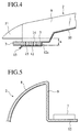
- the front fender 2 is formed by a curved outer surface port ion 8 forming a side surface of the vehicle body, a vertical surface portion 9 formed downward from an inner end of the outer surface portion 8, and a flange 10 inward extending from a lower end of the vertical surface portion 9, as in detail shown in Figs. 2 to 5.
- an overhang portion 11 obtained by curving only the outer surface portion 8 and the vertical surface portion 9 inward(without forming the flange 10) is formed in a front end portion of the front fender 2.
- a front end of the flange 10 and a portion of the vertical surface portion 9 corresponding thereto are extended to a lower side by deeply drawing these portions to the lower side more than the other portions.
- mounting portions 12 correspondingly for both end portions 7 of the radiator core upper 3 are respectively set in front ends of the flanges 10.
- the mounting portion 12 is formed at a position that is one stage lower than a normal surface in the front end of the flange 10, and is positioned below the overhang portion 11 at a degree of length "h", as shown in Fig. 4.
- the mounting portion 12 is formed at the position that is one stage lower than the normal surface, a vertical wall 12a with which corresponding one of both end portions 7 of the radiator core upper 3 can be brought into contact is formed at a rear end thereof. Further, a guide piece 13 extending so as to slant downward to the front side is formed at the front end of the mounting portion 12.
- the front end module 1 in order to attach the front end module 1, at first, the front end module 1 is suspended by a machine, and both end portions of the front end module 1, that is, both end portions 7 of the radiator core upper 3 are correspondingly aligned with the mounting portions 12 of the flanges 10.
- the front end module 1 is horizontally moved to the rear side from the front side while suspending the front end module 1, and both end portions 7 of the radiator core upper 3 are moved near the mounting portions 12 of the flanges 10 while passing through the lower side of the overhand portion 11.
- both end portions 7 of the radiator core upper 3 are correspondingly mounted on the mounting portions 12 of the flanges 10, and both are fastened by a fastening member such as bolts, nuts, or the like, whereby both end portions 7 of the radiator core upper 3 are attached.
- the mounting portion 12 is formed at the position that is one stage lower than the normal surface in the front end of the flange 10.
- both end portions 7 of the radiator core uppers 3 can be correspondingly mounted and attached onto the mounting portions 12 of the flanges 10 without interfering both end portions 7 of the radiator core upper 3 with the overhang portions 11 only by horizontally sliding the front end module 1 from the front side toward the rear side while suspending the front end module 1 by a machine, so that the operation can be very easily performed.
- the vertical walls 12a for correspondingly bringing the front ends of both end portions 7 of the radiator core upper 3 into contact therewith are respectively formed in the rear ends of the mounting portions 12, it is possible to position the radiator core upper 3 (the whole of the front end module 1) with respect to the front fenders 2.
- both bolt holes 14 and 15 are aligned with each other by correspondingly setting both end portions 7 of the radiator core upper 3 to the mounting portions 12 of the flanges 10, so that operability can be improved in this view.
- the guide pieces 13 are correspondingly formed in the front ends of the mounting portions 12, an operation of sliding both end portions 7 of the radiator core upper 3 from the front side so as to mount it on the mounting portion 12 can be further easily performed.
- both end portions 7 of the radiator core upper 3 and the mounting portions 12 of the flanges 10 are formed to be horizontal; however, both elements may be inclined at the seine angle.
- both of the elements are in a state of being a little downward slanted to the front side, each of clearances respectively formed in the lower sides of the overhang portions 11 is increased; however, an aligning operation between both of the elements can be easily performed.
- the overhang portion 11 is formed by inward curving only the outer surface portion 8 and the vertical surface portion 9; however, an inward flange may be formed from the lower end of the vertical surface portion 9 of the overhang portion 11 and/or the mounting portion 12 may be inward extended.
- radiator core upper 3 is the structural element of the front end module 1; however, it is of course possible to employ other parts to be cooled such as an air conditioning heat exchanger or the like in place of the radiator core upper 3, and even in this case, the same effects can be obtained by the same structure.
Landscapes
- Engineering & Computer Science (AREA)
- Chemical & Material Sciences (AREA)
- Combustion & Propulsion (AREA)
- Transportation (AREA)
- Mechanical Engineering (AREA)
- Body Structure For Vehicles (AREA)
Abstract
Description
Claims (8)
- A structure of a front end portion of a front fender (2) of a vehicle, the front fender (2) having an outer surface portion (8), a vertical surface portion (9) formed downward from an inner end of the outer surface portion (8), and a flange (10) formed inward from a lower end of the vertical surface portion (9), the structure comprising:an overhang portion (11) formed by inward curving of the outer surface portion (8) and the vertical surface portion (9); anda mounting portion (12) which is formed in a front end portion of the flange so as to be positioned immediately behind the overhang portion (11), and which mounts a corresponding end portion (7) of a radiator core upper (3) or a structural element of a front end module;
wherein the mounting portion (12) is at a position lower than the overhang portion (11). - A structure as claimed in claim 1, wherein the mounting portion (12) is formed at the position lower than the overhang portion (11) by downwardly extending the front end portion of the flange and a part of the vertical surface portion (9) corresponding to the mounting portion (12) .
- A structure as claimed in claim 1 or 2, wherein a vertical wall (12a) with which the said corresponding end portion (7) is brought into contact is formed at the rear end of the mounting portion (12).
- A structure as claimed in any preceding claim, wherein a guide piece (13) slanting downward at the front end of the mounting portion (12) is formed so as to guide the said corresponding end portion (7) during mounting.
- A structure as claimed in any preceding claim, wherein the radiator core upper (3) is incorporated in a front end module (1).
- A structure as claimed in any preceding claim, provided at both right and left sides of a vehicle.
- A structure of a front end portion of a front fender (2) of a vehicle, the front fender (2) having an outer surface portion (8), a vertical surface portion (9) formed downward from an inner end of the outer surface portion (8), and a flange (10) formed inward from a lower end of the vertical surface portion (9), the structure comprising:an overhang portion (11) formed by inward curving of the outer surface portion (8) and the vertical surface portion (9); andmounting means (12) for mounting a corresponding end portion (7) of a structural element (3) of a front end module (1), the mounting means (12) being formed in a front end portion of the flange (10) so as to be positioned immediately behind the overhang portion (11);
wherein the mounting means (12) is at a position lower than the overhang portion (11). - A method of mounting a front end module between front fenders of a vehicle, each front fender (2) having an outer surface portion (8), a vertical surface portion (9) formed downward from an inner end of the outer surface portion (8), and a flange (10) formed inward from a lower end of the vertical surface portion (9), an overhang portion (11) being formed in the front end portion of the front fender (2) by inward curving of the outer surface portion (8) and the vertical surface portion (9), the method comprising:suspending a front end module (1) including a structural element (3), in particular a radiator core upper, respective end portions (7) of the structural element (3) corresponding to respective mounting portions (12) formed in the respective flanges (10);moving the front end module (1) rearwards so that the respective ends portions (7) pass below the respective overhand portions (11); andmounting the respective end portions (7) on the respective mounting portions (12) of the flange (10) so as to attach the end portions to the vehicle.
Applications Claiming Priority (2)
| Application Number | Priority Date | Filing Date | Title |
|---|---|---|---|
| JP30967199 | 1999-10-29 | ||
| JP30967199A JP3755354B2 (en) | 1999-10-29 | 1999-10-29 | Front fender front end structure of the vehicle |
Publications (3)
| Publication Number | Publication Date |
|---|---|
| EP1095845A2 true EP1095845A2 (en) | 2001-05-02 |
| EP1095845A3 EP1095845A3 (en) | 2002-01-16 |
| EP1095845B1 EP1095845B1 (en) | 2004-07-21 |
Family
ID=17995882
Family Applications (1)
| Application Number | Title | Priority Date | Filing Date |
|---|---|---|---|
| EP00309204A Expired - Lifetime EP1095845B1 (en) | 1999-10-29 | 2000-10-19 | Structure of front end portion of front fender in vehicle |
Country Status (4)
| Country | Link |
|---|---|
| US (1) | US6334645B1 (en) |
| EP (1) | EP1095845B1 (en) |
| JP (1) | JP3755354B2 (en) |
| DE (1) | DE60012285T2 (en) |
Cited By (3)
| Publication number | Priority date | Publication date | Assignee | Title |
|---|---|---|---|---|
| FR2830229A1 (en) * | 2001-09-28 | 2003-04-04 | Valeo Equip Electr Moteur | FRONT PANEL OF MOTOR VEHICLE INCLUDING A BUMPER BEAM |
| EP1550602A1 (en) * | 2003-12-29 | 2005-07-06 | Arctic Cat Inc. | Multi-position fenders |
| EP1101690B1 (en) * | 1999-11-15 | 2006-01-25 | Compagnie Plastic Omnium | Front end of an automobile with positionning on the front wing of the vehicle |
Families Citing this family (25)
| Publication number | Priority date | Publication date | Assignee | Title |
|---|---|---|---|---|
| JP2001121941A (en) * | 1999-10-28 | 2001-05-08 | Denso Corp | Vehicle-mounted structure of heat exchanger |
| JP3832233B2 (en) * | 2000-12-05 | 2006-10-11 | スズキ株式会社 | Front body structure of the vehicle |
| US6877797B2 (en) * | 2001-07-18 | 2005-04-12 | Decoma International Inc. | Composite component integration panel for a motor vehicle |
| US6581708B2 (en) * | 2001-10-05 | 2003-06-24 | International Truck Intellectual Property Company, Llc | Quick mount vehicle engine compartment splash panel |
| US6893065B2 (en) * | 2001-10-16 | 2005-05-17 | Alcoa Inc. | Crash energy absorption assembly for a motor vehicle |
| US6755461B2 (en) | 2001-10-16 | 2004-06-29 | Aloca Inc. | Modular front end for a motor vehicle |
| US6769733B2 (en) | 2001-10-16 | 2004-08-03 | Alcoa Inc. | Bulkhead assembly for a motor vehicle |
| US7163076B2 (en) | 2001-10-16 | 2007-01-16 | Alcoa Inc. | Drive train assembly for a motor vehicle |
| US7163219B2 (en) | 2002-10-16 | 2007-01-16 | Alcoa Inc. | Control arm for motor vehicle suspension system |
| US6948769B2 (en) * | 2003-12-22 | 2005-09-27 | Nissan Technical Center North America, Inc. | Vehicle front end structure |
| US7810876B2 (en) * | 2007-01-11 | 2010-10-12 | Ford Motor Company | Vehicle having a rear end body structure |
| US7849601B2 (en) * | 2007-01-11 | 2010-12-14 | Ford Motor Company | Method of manufacturing a vehicle |
| US8177277B2 (en) * | 2007-01-11 | 2012-05-15 | Ford Motor Company | Vehicle having a body panel |
| US7717465B2 (en) * | 2007-01-11 | 2010-05-18 | Ford Motor Company | Vehicle having an engine support structure |
| US7677649B2 (en) * | 2007-01-11 | 2010-03-16 | Ford Motor Company | Vehicle having an interlocking floor assembly |
| US8317964B2 (en) * | 2007-01-11 | 2012-11-27 | Ford Motor Company | Method of manufacturing a vehicle |
| US7798560B2 (en) * | 2007-01-11 | 2010-09-21 | Ford Motor Company | Vehicle body structure |
| US7850226B2 (en) * | 2007-01-11 | 2010-12-14 | Ford Motor Company | Vehicle having a passenger compartment body structure |
| US8123284B2 (en) * | 2007-01-11 | 2012-02-28 | Ford Motor Company | Vehicle body component and mating feature |
| US7618087B2 (en) * | 2007-01-11 | 2009-11-17 | Ford Motor Company | Vehicle having a front end body structure |
| US7591502B2 (en) * | 2007-01-11 | 2009-09-22 | Ford Motor Company | Tunable inner fender structure |
| US7703841B2 (en) * | 2007-01-11 | 2010-04-27 | Ford Motor Company | Vehicle body assembly |
| US8038205B2 (en) * | 2007-01-11 | 2011-10-18 | Ford Motor Company | Vehicle having a passenger compartment body structure |
| KR101361372B1 (en) * | 2012-06-18 | 2014-02-10 | 기아자동차주식회사 | Device for assembling fender panel of vehicle |
| US9481402B1 (en) | 2015-05-26 | 2016-11-01 | Honda Motor Co., Ltd. | Methods and apparatus for supporting vehicle components |
Family Cites Families (13)
| Publication number | Priority date | Publication date | Assignee | Title |
|---|---|---|---|---|
| DE3417337C2 (en) * | 1984-05-10 | 1986-04-24 | Adam Opel AG, 6090 Rüsselsheim | Arrangement of a motor vehicle front part made of plastic on the vehicle body |
| US4573734A (en) * | 1984-12-10 | 1986-03-04 | Gass Gene C | Unisocket construction for front compartment of a unitized automobile body |
| JPS63212184A (en) * | 1987-02-27 | 1988-09-05 | Nissan Motor Co Ltd | Installing method for car body end panel |
| DE3809456C2 (en) * | 1987-03-27 | 1995-06-14 | Nissan Motor | Vehicle body and method of manufacturing the same |
| JP2712345B2 (en) | 1988-08-29 | 1998-02-10 | 松下電器産業株式会社 | IC card recording / reproducing device |
| JPH085408B2 (en) | 1989-03-22 | 1996-01-24 | 日産自動車株式会社 | Body front structure |
| US5358304A (en) * | 1989-12-21 | 1994-10-25 | Mazda Motor Corporation | Front body structure of a vehicle and assembling method |
| DE69022967T3 (en) * | 1989-12-21 | 1999-04-15 | Mazda Motor Corp., Hiroshima | Front end body of a vehicle. |
| JPH04141308A (en) * | 1990-09-27 | 1992-05-14 | Mazda Motor Corp | Method and apparatus for working reference hole in car body |
| JP2565377Y2 (en) * | 1991-09-06 | 1998-03-18 | マツダ株式会社 | Car front body structure |
| JPH05170135A (en) * | 1991-12-18 | 1993-07-09 | Mazda Motor Corp | Front body structure of automobile |
| JP3323289B2 (en) | 1993-07-20 | 2002-09-09 | 株式会社ニフコ | Fuel cut valve |
| JP3269352B2 (en) * | 1995-09-14 | 2002-03-25 | 日産自動車株式会社 | Front fender mounting structure |
-
1999
- 1999-10-29 JP JP30967199A patent/JP3755354B2/en not_active Expired - Fee Related
-
2000
- 2000-10-19 EP EP00309204A patent/EP1095845B1/en not_active Expired - Lifetime
- 2000-10-19 DE DE60012285T patent/DE60012285T2/en not_active Expired - Lifetime
- 2000-10-27 US US09/697,164 patent/US6334645B1/en not_active Expired - Fee Related
Cited By (5)
| Publication number | Priority date | Publication date | Assignee | Title |
|---|---|---|---|---|
| EP1101690B1 (en) * | 1999-11-15 | 2006-01-25 | Compagnie Plastic Omnium | Front end of an automobile with positionning on the front wing of the vehicle |
| FR2830229A1 (en) * | 2001-09-28 | 2003-04-04 | Valeo Equip Electr Moteur | FRONT PANEL OF MOTOR VEHICLE INCLUDING A BUMPER BEAM |
| WO2003029068A1 (en) * | 2001-09-28 | 2003-04-10 | Valeo Thermique Moteur | Front panel of a motor vehicle comprising a bumper beam |
| US7011360B2 (en) * | 2001-09-28 | 2006-03-14 | Valeo Thermique Moteur | Front panel of a motor vehicle comprising a bumper beam |
| EP1550602A1 (en) * | 2003-12-29 | 2005-07-06 | Arctic Cat Inc. | Multi-position fenders |
Also Published As
| Publication number | Publication date |
|---|---|
| JP2001122158A (en) | 2001-05-08 |
| DE60012285T2 (en) | 2005-07-28 |
| JP3755354B2 (en) | 2006-03-15 |
| EP1095845B1 (en) | 2004-07-21 |
| DE60012285D1 (en) | 2004-08-26 |
| US6334645B1 (en) | 2002-01-01 |
| EP1095845A3 (en) | 2002-01-16 |
Similar Documents
| Publication | Publication Date | Title |
|---|---|---|
| EP1095845B1 (en) | Structure of front end portion of front fender in vehicle | |
| US5573299A (en) | Module carrier structure for vehicle front end having a groove for a wire harness | |
| JP3697976B2 (en) | Front end module mounting structure | |
| US5066057A (en) | Bumper structure | |
| US6349953B1 (en) | Structure of suspension mounting portion and assembling method thereof | |
| JPH01156154A (en) | Radiator frame for automobile | |
| US8210300B2 (en) | Systems and methods for assembling a front end module to a vehicle | |
| US20060081354A1 (en) | Radiator core support structure | |
| WO2016189940A1 (en) | Tractor | |
| JP2907502B2 (en) | How to assemble the front body of the vehicle | |
| JP3820423B2 (en) | Mounting structure for vehicle lamp | |
| US4895405A (en) | Bumper mounting structure for a vehicle | |
| JP3125573B2 (en) | Vehicle radiator core support structure | |
| JP2898339B2 (en) | Vehicle front body structure and vehicle body assembly method | |
| GB2352693A (en) | Integrally moulded fender cover and step | |
| CA2566946A1 (en) | Front structure for vehicle | |
| JP2848666B2 (en) | Vehicle front body structure and vehicle body assembly method | |
| JP3583710B2 (en) | Motorcycle headlamp mounting structure | |
| JP3308112B2 (en) | Car body front structure | |
| JPH10157467A (en) | Electric car | |
| JPH07172345A (en) | Vehicle front structure | |
| JP2823735B2 (en) | Riding paddy working machine | |
| KR100931161B1 (en) | Radiator installation structure for automobile | |
| JP3310368B2 (en) | Module carrier structure at front end of vehicle | |
| JPH07165117A (en) | Vehicle front structure |
Legal Events
| Date | Code | Title | Description |
|---|---|---|---|
| PUAI | Public reference made under article 153(3) epc to a published international application that has entered the european phase |
Free format text: ORIGINAL CODE: 0009012 |
|
| 17P | Request for examination filed |
Effective date: 20001117 |
|
| AK | Designated contracting states |
Kind code of ref document: A2 Designated state(s): DE GB Kind code of ref document: A2 Designated state(s): AT BE CH CY DE DK ES FI FR GB GR IE IT LI LU MC NL PT SE |
|
| AX | Request for extension of the european patent |
Free format text: AL;LT;LV;MK;RO;SI |
|
| PUAL | Search report despatched |
Free format text: ORIGINAL CODE: 0009013 |
|
| AK | Designated contracting states |
Kind code of ref document: A3 Designated state(s): AT BE CH CY DE DK ES FI FR GB GR IE IT LI LU MC NL PT SE |
|
| AX | Request for extension of the european patent |
Free format text: AL;LT;LV;MK;RO;SI |
|
| 17Q | First examination report despatched |
Effective date: 20020626 |
|
| AKX | Designation fees paid |
Free format text: DE GB |
|
| GRAP | Despatch of communication of intention to grant a patent |
Free format text: ORIGINAL CODE: EPIDOSNIGR1 |
|
| GRAS | Grant fee paid |
Free format text: ORIGINAL CODE: EPIDOSNIGR3 |
|
| GRAA | (expected) grant |
Free format text: ORIGINAL CODE: 0009210 |
|
| AK | Designated contracting states |
Kind code of ref document: B1 Designated state(s): DE GB |
|
| REG | Reference to a national code |
Ref country code: GB Ref legal event code: FG4D |
|
| REG | Reference to a national code |
Ref country code: IE Ref legal event code: FG4D |
|
| REF | Corresponds to: |
Ref document number: 60012285 Country of ref document: DE Date of ref document: 20040826 Kind code of ref document: P |
|
| PLBE | No opposition filed within time limit |
Free format text: ORIGINAL CODE: 0009261 |
|
| STAA | Information on the status of an ep patent application or granted ep patent |
Free format text: STATUS: NO OPPOSITION FILED WITHIN TIME LIMIT |
|
| 26N | No opposition filed |
Effective date: 20050422 |
|
| PGFP | Annual fee paid to national office [announced via postgrant information from national office to epo] |
Ref country code: GB Payment date: 20081015 Year of fee payment: 9 |
|
| PGFP | Annual fee paid to national office [announced via postgrant information from national office to epo] |
Ref country code: DE Payment date: 20091015 Year of fee payment: 10 |
|
| PG25 | Lapsed in a contracting state [announced via postgrant information from national office to epo] |
Ref country code: GB Free format text: LAPSE BECAUSE OF NON-PAYMENT OF DUE FEES Effective date: 20091019 |
|
| REG | Reference to a national code |
Ref country code: DE Ref legal event code: R119 Ref document number: 60012285 Country of ref document: DE Effective date: 20110502 |
|
| PG25 | Lapsed in a contracting state [announced via postgrant information from national office to epo] |
Ref country code: DE Free format text: LAPSE BECAUSE OF NON-PAYMENT OF DUE FEES Effective date: 20110502 |