EP1095628A2 - Planning minimally invasive procedures for in - vivo placement of objects - Google Patents
Planning minimally invasive procedures for in - vivo placement of objects Download PDFInfo
- Publication number
- EP1095628A2 EP1095628A2 EP00309491A EP00309491A EP1095628A2 EP 1095628 A2 EP1095628 A2 EP 1095628A2 EP 00309491 A EP00309491 A EP 00309491A EP 00309491 A EP00309491 A EP 00309491A EP 1095628 A2 EP1095628 A2 EP 1095628A2
- Authority
- EP
- European Patent Office
- Prior art keywords
- patient
- virtual
- image
- planning
- trajectory
- Prior art date
- Legal status (The legal status is an assumption and is not a legal conclusion. Google has not performed a legal analysis and makes no representation as to the accuracy of the status listed.)
- Ceased
Links
Images


Classifications
-
- A—HUMAN NECESSITIES
- A61—MEDICAL OR VETERINARY SCIENCE; HYGIENE
- A61N—ELECTROTHERAPY; MAGNETOTHERAPY; RADIATION THERAPY; ULTRASOUND THERAPY
- A61N5/00—Radiation therapy
- A61N5/10—X-ray therapy; Gamma-ray therapy; Particle-irradiation therapy
- A61N5/103—Treatment planning systems
-
- A—HUMAN NECESSITIES
- A61—MEDICAL OR VETERINARY SCIENCE; HYGIENE
- A61B—DIAGNOSIS; SURGERY; IDENTIFICATION
- A61B90/00—Instruments, implements or accessories specially adapted for surgery or diagnosis and not covered by any of the groups A61B1/00 - A61B50/00, e.g. for luxation treatment or for protecting wound edges
- A61B90/36—Image-producing devices or illumination devices not otherwise provided for
-
- A—HUMAN NECESSITIES
- A61—MEDICAL OR VETERINARY SCIENCE; HYGIENE
- A61B—DIAGNOSIS; SURGERY; IDENTIFICATION
- A61B34/00—Computer-aided surgery; Manipulators or robots specially adapted for use in surgery
- A61B34/10—Computer-aided planning, simulation or modelling of surgical operations
-
- A—HUMAN NECESSITIES
- A61—MEDICAL OR VETERINARY SCIENCE; HYGIENE
- A61B—DIAGNOSIS; SURGERY; IDENTIFICATION
- A61B6/00—Apparatus or devices for radiation diagnosis; Apparatus or devices for radiation diagnosis combined with radiation therapy equipment
- A61B6/58—Testing, adjusting or calibrating thereof
- A61B6/582—Calibration
- A61B6/583—Calibration using calibration phantoms
- A61B6/584—Calibration using calibration phantoms determining position of components of the apparatus or device using images of the phantom
-
- A—HUMAN NECESSITIES
- A61—MEDICAL OR VETERINARY SCIENCE; HYGIENE
- A61B—DIAGNOSIS; SURGERY; IDENTIFICATION
- A61B90/00—Instruments, implements or accessories specially adapted for surgery or diagnosis and not covered by any of the groups A61B1/00 - A61B50/00, e.g. for luxation treatment or for protecting wound edges
- A61B90/10—Instruments, implements or accessories specially adapted for surgery or diagnosis and not covered by any of the groups A61B1/00 - A61B50/00, e.g. for luxation treatment or for protecting wound edges for stereotaxic surgery, e.g. frame-based stereotaxis
-
- A—HUMAN NECESSITIES
- A61—MEDICAL OR VETERINARY SCIENCE; HYGIENE
- A61N—ELECTROTHERAPY; MAGNETOTHERAPY; RADIATION THERAPY; ULTRASOUND THERAPY
- A61N5/00—Radiation therapy
- A61N5/10—X-ray therapy; Gamma-ray therapy; Particle-irradiation therapy
- A61N5/1001—X-ray therapy; Gamma-ray therapy; Particle-irradiation therapy using radiation sources introduced into or applied onto the body; brachytherapy
- A61N5/1027—Interstitial radiation therapy
Definitions
- the present invention relates to the field of interactive planning for image-guided surgery. It finds particular application in conjunction with the planning and implementation stages of minimally invasive stereotactic surgical procedures performed in CT imaging systems using a localization device to orient a surgical tool such as a brachytherapy needle or the like for planning and placement of objects within the body of a patient, and will be described with particular reference thereto. It is to be appreciated, however, that the invention is also applicable to a wide range of imaging equipment and techniques, for example ultrasonic and magnetic resonance imaging devices, and to a broad range of minimally invasive surgical procedures including many forms of surgery for placing objects at precise points within a patient such as interventional radiology procedures and others.
- brachytherapy in which radioactive seeds are inserted into cancerous tissue, thereby attacking cancer cells.
- brachytherapy in which radioactive seeds are inserted into cancerous tissue, thereby attacking cancer cells.
- One method for inserting the seeds in the case of prostate brachytherapy involves trans-rectal ultrasound image guidance.
- One disadvantage of such a procedure is that preoperative planning and visualization information is limited. Also, the procedure is uncomfortable for the patient.
- the patient is first scanned to generate a volumetric image data set. Thereafter, the collected patient image data set is forwarded to an off-line dose planning system. On a remote computer, virtual "seeds" are placed on axial view-graphs of the patient derived from the patient image data set to provide a virtual prescribed cumulative seed distribution.
- the location of the virtual seeds in x, y, z coordinates in the patient's image data set are stored so that when the patient is repositioned on the scanning apparatus, sometimes days later, the physical radioactive seeds can be introduced into the body of the patient at the physical x, y, z coordinates corresponding to the x, y, z coordinates defined by the virtual seeds that were "placed" during the off-line planning stage.
- the patient during the implementation phase, the patient must be re-scanned in the imaging apparatus, typically days later.
- the initial dose plan becomes unreliable and is therefore no longer valid.
- a similar disadvantageous result obtains when the tumor or other target tissue within the patient moves between the pre-operative planning scan and the implementation phase. In either case, the brachytherapist is provided with no means to adopt a new plan or otherwise adjust the original plan.
- a method and apparatus for planning a minimally invasive procedure for in-vivo placement of an object within a patient is provided.
- the method of planning placement of objects within the body of a patient includes scanning the patient includes scanning the patient in an imaging device to generate a volumetric image data set of the patient. Thereafter, an image of the patient derived from the volumetric image data set is displayed on a human readable display device.
- a virtual target point is selected in the image of the patient by identifying a first set of virtual coordinates in the patient image.
- a virtual trajectory for inserting an object into the patient is selected by identifying a virtual path extending from the selected virtual target point and out from the body of the patient.
- the virtual trajectory is displayed on the human readable display device together with the image of the patient.
- the patient image is a multi-planar reformatted image and the image is coincident with the virtual trajectory so that the entire trajectory is visible on the display device.
- the apparatus for planning placement of objects within the body of a patient includes an imaging device for scanning the patient to generate a volumetric image data set of the patient.
- a human readable display device displays an image of the patient derived from the volumetric image data set.
- Processing means together with a control console are provided for selecting a virtual target point in the image of the patient and for selecting a virtual trajectory for inserting an object into the patient.
- the virtual target point is identified on the display device by selecting a first set of virtual coordinates in the image of the patient.
- the virtual trajectory is selected by identifying a virtual path extending from the selected virtual target point and extending outwardly from the body of the patient image.
- a display means is provided for displaying the virtual trajectory on a human readable display device together with the image of the patient.
- a multi-planar reformatted image of the patient is generated and the virtual trajectory and the planar image of the patient are coincident.
- Such a method and apparatus provides for planning and executing minimally invasive procedures for in-vivo placement of objects that enables non-invasive pre-operation virtual seed placement and dose distribution planning using visualization information showing a patient's anatomy together with a set of single point targets within the patient's body and a corresponding set of trajectories through the skin and body of the patient leading to the target points.
- such a method and apparatus for planning interventional radiological procedures provides dose distribution visualization information so that the planning interventionist can quickly and easily derive a dose plan strategy commensurate with a pathological prognosis of the patient as determined from the patient's pre-operative volumetric image data set.
- the visualization information includes a cumulative dose distribution volume defining a plurality of dose level contours surrounding each virtual seed for visualization in slices taken through the patient's image volume data set at various selected angles and orientations.
- the dose plan preferably includes visualization information showing a prescription dose profile as well as a low dose profile surrounding the virtual seeds.
- the method and apparatus further includes a localizing device for implementing the dose plan by providing a means for precisely aligning an interventional tool along each of the one or more planning trajectories so that the radioactive seeds can be inserted at each target point and along each planning trajectory in turn according to the previously derived plan.
- the method and apparatus provides visualization information in the form of at least two axial image slices showing the virtual needle entry point and target point, as well as a pair of multi-planar reformatted (MPR) image views of the patient's image data set along the trajectory of a virtual needle, each view being combined in an overlayed fashion with the dose distribution volume data set of the patient.
- MPR multi-planar reformatted
- the interventionist moves the localizing device and interventional tool into a range of positions relative to the patient until the multiple views of the physical tool shown on the display device are in alignment with the virtual trajectories shown on the display device and developed during the planning stage.
- the localizing device is selectively locked in place relative to the patient so that the interventional seed carrying tool can be translated along the planning trajectory to a desired depth for precise placement of the radioactive seed or other selected object within the patient's body.
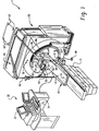
- a system 1 for planning and executing minimally invasive surgical procedure for in-vivo placement of objects includes a patient table or support 10 defining a patient supporting surface 12 that is mounted for longitudinal movement relative to a base portion 14 .
- the base portion 14 includes a motor for raising and lowering the patient support surface 12 and for moving the patient support surface longitudinally.
- Position encoders are also provided for generating electrical signals indicative of the height and longitudinal position of the patient support.
- the patient support includes a calibration and verification area 16 disposed at a known, fixed location.
- a planning, preferably volumetric diagnostic imaging apparatus 20 is disposed in axial alignment with the patient table such that a patient or subject on the patient support surface 12 can be moved into and through a bore 22 of the volumetric imager.
- the volumetric imager is a CT scanner which includes an x-ray tube mounted for rotation about a preselected plane.
- the x-ray tube projects a fan shaped beam of radiation through a ring 24 of radiation translucent material, through the patient support 12, the a region of interest of the subject, and to a ring or arc of radiation detectors disposed opposite the x-ray tube.
- a series of data lines are generated, which data lines are reconstructed into at least a slice image by a reconstruction processor included in a control console 30 .
- the patient support 12 moves longitudinally as the x-ray tube is rotating around the subject such that a selected volume of the patient is scanned along a spiral path or a series of slices.
- the position of the x-ray tube is monitored by a rotational position encoder, and the longitudinal position of the patient support is monitored by a longitudinal position encoder within the couch 10 .
- the reconstruction processor reconstructs a volumetric image representation from the generated data lines.
- the control console 30 typically includes one or more monitors 32 and an operator input device 34 , such as a keyboard, trackball, mouse, or the like.
- An interventionists control and display console 36 is supported from overhead on a track atop the CT scanner.
- a mechanical arm assembly 40 is supported from overhead by a carriage 42 movable on a track system 44 affixed to the top of the volumetric diagnostic imaging apparatus 20 as generally shown.
- the carriage is preferably lockable in one or more predetermined fixed locations on the oval track so that a minimally invasive surgical instrument 50 carried on an interchangeable surgical instrument guidance device 52 can be positioned in monitored positions and orientations by an interventionist in preparation for and in carrying out a surgical procedure in accordance with the present invention.
- the surgical instrument in the illustrated embodiment includes a manually guided brachytherapy needle 54 (e.g. MICK application) adapted to engage the guidance device 52 and slide therealong to carry a radioactive seed or pellet on the tip of the needle into the body of the patient to deposit the seed at precise predetermined locations.
- MICK application manually guided brachytherapy needle 54
- the mechanical arm assembly 40 includes a plurality of arm segments which are interconnected by pivot members. Encoders or position resolvers at each joint monitor the relative articulation and rotation of the arm segments relative to each other. Position encoders or resolvers are also provided along the mechanical interconnection of the arm with the imaging apparatus 20. In this manner, the mechanical interconnection which is measured by the resolvers and encoders provides an accurate indication of the position and orientation of the guidance device 52 and the surgical instrument 50 carried thereon relative to the imaging apparatus 20 .
- a tip of the guidance device or a pointer carried thereon is touched to the calibration and verification area 16 and an assessment is made whether the electronic signals indicative of patient support location and surgical instrument location, in fact, place both at the same point in space.
- one or more markers 56 on the imaging apparatus in a fixed, known location relative to the plane of rotation of the x-ray beam is touched by the tip of the guidance device or pointer and the electronic position signals are compared to be sure that the coordinate systems of the volumetric scanner 20 and the guidance device 52 are accurately correlated.
- mechanisms other than the arm assembly 40 and interchangeable surgical instrument guidance device 52 carried thereon are contemplated for monitoring the position of the surgical instrument 50 .
- a plurality of transmitters such as light emitting diodes 60 are mounted on the guidance device 52 or on a localizing device (not shown) in a fixed, known relationship to the surgical instrument.
- An array of receivers 62 is mounted in a fixed relationship to the imaging apparatus 20 , preferably affixed to the ceiling of the room. Each time the emitters are actuated and the emitted signal received by the receivers, the position and orientation of the localization device and therefore of the surgical instrument carried thereon are accurately and quickly calculated using geometric triangulation techniques.
- the coordinate systems of the surgical instrument 50 and the imaging apparatus 20 can be readily correlated.
- the localization device By positioning the localization device on the calibration and verification area 16 formed on the patient table 10 , the coordinate system of the surgical instrument 50 and the patient table 10 can be readily coordinated.
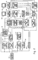
- an instrument coordinate circuit 100 determines the position and trajectory of the surgical instrument 50 carried on the guidance device 52 in instrument space, particularly a coordinate system of the instrument.
- the instrument coordinate circuit is connected with resolvers on the mechanical arm assembly 40 in the mechanical arm embodiment and with the receivers 62 in the emitter embodiment to receive signals indicative of changes of position and orientation of the instrument in instrument space.
- An instrument-planning scanner correlating processor 102 determines the correlation or transform between the minimally invasive surgical instrument 50 and the volumetric scanner 20 coordinate systems. The correlation or transform is normally described in terms of offset (particularly offset along the axis of the patient support), angular offset or rotation, and scaling.
- the instrument 50 is touched to three or more markers 56 which are in a known relationship to the volumetric scanner coordinate system.
- the offset between the two coordinate systems is determined.
- the angular difference between the rays from the characteristic point to each point in each coordinate system is determined.
- the scaling factor is determined.
- the transform or relationship between the volumetric scanner and the instrument coordinate systems are determined during a calibration of the mechanical system during installation. The touching of the markers can be eliminated or used merely to confirm that the instrument and the CT scanner coordinates have not become misaligned.
- An instrument-to-patient table correlating processor 104 performs a similar calculation or uses similar known physical relationships to determine the correlation or transform between the patient table and the surgical instrument.
- a phantom having a multiplicity of marks is disposed in a known position on the table to provide a larger number of corresponding points in both coordinate systems for the correlating process. Images of the phantom can be used to derive transforms between the patient table space and planning or real time image coordinate systems.
- Table resolvers 110 located in the patient table contribute vertical and longitudinal offsets to the correlation between the instrument and the patient table when the table is raised or lowered and when the patient support 12 is moved axially.
- An instrument-to-patient correlation processor 112 determines the correlation between the instrument coordinate system and a patient coordinate system. Again, this is preferably done by placing the instrument on three or more known reference points on the patient. Such points may include readily identifiable anatomical structures such as the tip of the nose, distinctive points on bones, fiducial markers that are imaged during the volumetric imaging process, or the like.
- An instrument-to-volumetric image coordinate system transform processor 120 receives the correlation or transform from the instrument-to-planning scanner correlating processor 102 .
- the instrument-to-volumetric image processor operates on input position and orientation coordinates in image space to transform them into volumetric image data space or vice-versa. Knowing the position of the surgical instrument in volumetric or planning data space enables the position of the instrument and orientation of same to be superimposed on the volumetric planning image data.
- the patient is positioned in the imaging apparatus and a volumetric image data set is generated.
- the volumetric image data set is stored in a volumetric or planning data memory 122 .
- the position of the patient during the generation of the planning data, particularly as the table moves to generate spiral or slice data, is stored in conjunction with the volumetric planning data such that the data is correlated with the patient table coordinate system.
- the operator control 30 controls the volume planning image data memory or a video processor 124 such that selected slices, projection images, surface renderings, or other conventional displays of the data are generated for display on a planning image display 126 .
- the planning image display includes corresponding sagittal, coronal, and transverse axial slices through one or more selected common points of intersection.
- FIGURE 3 is a diagrammatical illustration of a preferred set of controls 132 available to an interventionist as the operator input device at the console 30 .
- a track ball 134 embedded within the console is available to the interventionist to translate the virtual surgical instrument 130 relative to the planning image displayed on the planning image display 126 at the console.
- Rotation of the virtual surgical instrument is enabled by a theta ring 136 .
- the length or "depth” of the virtual surgical instrument is increased using a first depth input key 138 and decreased using a second depth input key 140 .
- a "view port toggle" input key 142 is used to select a view port as an active view port from among the set of view ports available for viewing on the display to be described below in connection with FIGURE 4.
- a "prior needle” input key 144 and a “next needle” input key 146 are disposed on the console for selecting an active virtual surgical instrument from among a plurality of virtual surgical instruments that are displayed on the planning image display at the console for procedures involving placement of two or more radioactive seeds or other objects within the patient.
- the selected active virtual needle is preferably displayed in a highlighted fashion so that the interventionist can visually distinguish the active virtual needle from among the set of available but non-selected virtual needles.
- a "save needle” input key 148 is provided to enable an interventionist to store a set of x, y, z coordinates in the system corresponding to the tip of the active virtual needle after it is moved to a desired location in the displayed image of the patient.
- the "delete needle” input key 150 deactivates the coordinates of the selected needle.
- a keyboard portion 152 is provided to enable an operator to enter data such as comments, notes, or descriptions into the data set as desired.
- a "send to robot" input key 154 is provided to enable an operator to initiate the transfer of a set of selected x, y, z coordinates of multiple target points and trajectories associated therewith to an operatively associated robotic system (not shown) for automated robotic insertion of the radioactive seeds into the patient at the appropriate locations.
- the console 30 is integrated with the imaging apparatus 20 .
- a representative patient planning image volume display 160 is divided into four quadrants or view ports including an upper left first transverse axial view port 162 , and upper right second transverse axial view port 164 , a lower left proxy transverse axial to coronal view port 166 , and lastly, a lower right proxy transverse axial to sagittal view port 168.
- the top two view ports 162, 164 are coordinated with the bottom two view ports 166, 168.
- the top two view ports 162, 164 are axial slice images 172, 174 taken through the patient's image volume data set at the entry or insertion point 180 of the virtual needle 130 into the patient's body and at the terminus or head point 182 of the virtual needle 130 at a selected target point within the patient, respectively.
- the bottom two view ports 166, 168 are multi-planar reformatted (MPR) images 176, 178 that are co-planar with the virtual needle trajectory 184 of the virtual surgical instrument 130 to provide visualization information to the interventionist through multiple axial slices of the patient image data set along the length of the instrument trajectory.
- MPR multi-planar reformatted
- the lower left view port 166 is an MPR image 176 of the patient showing a proxy transverse axial-to-coronal view of the patient with the virtual needle trajectory 184 extending from the virtual needle 130 between an insertion point 180 on the patient's skin and a head or target point 182 located within the patient.
- the plane defined by the proxy transverse axial-to-coronal MPR image 176 of the patient intersects the line defined by the virtual needle trajectory 184 . In that way, the virtual needle trajectory 184 is co-planar with the image displayed so that the entire trajectory path can be visualized.
- the lower right view port 168 is an MPR image 178 of the patient showing a proxy transverse axial-to-sagittal view of the patient with the virtual needle trajectory 184 extending from the virtual needle 130 between the insertion point 180 and the head or target point 182 .
- the plane defined by the proxy transverse axial-to-sagittal MPR image 178 of the patient intersects the line defined by the virtual needle trajectory. In that way, the virtual needle trajectory 184 is co-planar with the image displayed so that the entire trajectory path can be visualized.
- the interventionist presses the "save needle" input key 148 to store a set of x, y, z coordinates in the system corresponding to the tip of the virtual needle and identifying the angulation and coordinates of the physical surgical instrument 50 carried on the arm assembly 40 for exactly duplicating the path of the virtual needle trajectory with the physical instrument.
- the operator uses the track ball 134 and/or the theta ring 136 to move the virtual needle 130 into the appropriate position and orientation to define a more appropriate insertion pathway and target point.
- each of the images 172-178 displayed on the corresponding view ports 162-168 are simultaneously updated substantially in real time to provide the interventionist with a set of cross sectional slices through the patient's image volume data set so that suitable planning decisions can be made.
- One significant advantage of the invention is that major organ, veins, and other structures are visualized during the planning stage so that one or more object placement trajectories can be selected to ensure that those tissues identified are avoided during the physical object placement process.
- the display 160 is used by the interventionist to select trajectories that avoid major organs, etc.
- the proxy transverse axial to coronal view port 166 is updated as the virtual needle is moved so that the image displayed remains co-planar with the virtual needle trajectory 184.
- the proxy transverse axial to sagittal view port 168 is updated so that the displayed image is co-planar with the virtual needle.
- each of the axial view ports 162, 164 are updated as well.
- the first transverse axial view port 162 is updated to display an axial slice image of the patient that is coincident with the virtual insertion point 180 and the second transverse axial view port 164 is updated to display an axial slice image that is coincident with the virtual needle head or target point 182.
- a virtual radioactive seed 190 is "deposited” in the tissue at the head point 182 of the then active virtual surgical instrument 130 and displayed as shown. Substantially simultaneously therewith, the x, y, z coordinates of the virtual radioactive seeds are stored in the system and a high or "prescription" dose profile 192 is displayed surrounding the virtual radioactive seed 190 as generally shown. In addition, a low dose profile 194 is displayed surrounding the prescription dose profile 192 .
- the high and low prescription dose profiles correspond to concentrically located spheres centered on the x, y, z coordinate of the virtual radioactive seed 190.
- the images shown in FIGURE 4 are planar slice images taken through the patient's volumetric image data set and, accordingly, the high and low dose profiles 192, 194 appear as concentric circles.
- the high and low dose profiles are calculated according to known methods such as described in A Practical Manual of Brachytherapy, by B. Pierquin and G. Marinetto.
- the expression high or prescription dose is intended to refer to a dosage intensity level intended for irradiating a tumorous mass or the like.
- the expression low dosage profile includes a dosage intensity intended to affect secondary tissue surrounding the cancerous or tumorous growth.
- the lower left MPR image 176 illustrates the case where a pair of first and second virtual radioactive seeds 200, 202 are placed in a virtual sense during the planning phase in close proximity to each other.
- the high prescription dose profile 204 of the first radioactive seed 200 is only slightly spaced apart from the high or prescription dose profile 206 of the second radioactive seed 202 due to the small relative separation between the virtual radioactive seeds 200, 202.
- the low dose profile rings surrounding the seeds overlap and are therefore represented in the planar images 174, 176 as an agglomeration 208 surrounding the pair of high dose profiles 204, 206.
- FIGURE 5 A schematic representation of a dose curve generator system 210 in accordance with the present invention is shown in FIGURE 5.
- a dose lookup table 212 is provided for storing the values of radioactive seed dose contribution at a predetermined range of distances from the source.
- the dose lookup table 212 is preferably derived from radioactive seed dose distribution calculations well known in the art.
- the dose lookup table 212 is accessed by an adder circuit 214 and added to a cumulative dose volume 216 .
- the cumulative dose volume stores the current dose level at all pixels in a volume space corresponding to the CT image volume 218 corresponding to the patient's volumetric image data set. To that end, preferably, there is a one-to-one correspondence between pixels in the cumulative dose volume 216 with pixels in the CT image volume 218 .
- a first MPR generator 220 generates a first MPR slice 222 from the CT image volume 218 based on the position and orientation of the virtual needle 130 .
- a second MPR generator 224 generates a second MPR slice 226 from the cumulative dose volume 216 .
- the first and second MPR slices 222, 226 mirror each other relative to their respective image volume sets 216, 216 .
- the first and second MPR slices are co-registered.
- An axial slice through the cumulative dose volume 216 is calculated using an axial slice volume generator 228 .
- an axial slice volume generator 228 With regard to the visualization of the dose distribution profile, it is to be appreciated that only a single axial slice through the cumulative dose volume 216 is needed at the transverse slice corresponding to the head point 182 of the virtual needle. It is not necessary to calculate an axial slice of the cumulative dose volume 216 at the insertion point 180 because it is unlikely that any virtual radioactive seeds 190 will be placed there (at the skin surface).
- First and second dose display curves 230, 232 are generated by first and second bi-value dose contour generators 234, 236 , respectively.
- the first and second dose display curves 230, 232 are thereafter added onto the MPR image display 237 as a combined display 238 .
- the combined display 238 is therefore preferably the combined display of a slice taken through the CT image volume 218 together with a corresponding slice taken through the cumulative dose volume 216 with the bi-value dose contours added thereto.
- FIGURE 6 is an illustration of the preferred set of images of planes extending through the patient image volume data set for use during the implementation stage of the present invention.
- the set of images are displayed on an implementation image display 128 carried from overhead the interventionist control and display console 36 (Fig. 1) of the imaging apparatus 20.
- the implementation stage is the process by which physical radioactive seeds or other objects are implanted within the patient in accordance with the strategy developed during the virtual planning and visualization stage described above.
- the implementation phase is commenced substantially immediately after the planning stage and preferably without removing the patient from the patient table 10.
- the figure shows a set of view ports 262-268 that display an example of a dose distribution plan in the various axial and MPR images 272-278 .
- the dose distribution plan shown by way of example includes a first set 280 of three virtual needle trajectories 282-286 extending through the patient image volume data set toward a corresponding set of virtual seed placement points 292-296 .
- the seed placement points and the trajectories illustrated in the display 160 shown in Fig. 6 were determined during the planning phase in a manner as described above and are for purposes of explanation of the implementation phase of the invention.
- the display 260 is divided into four quadrants or view ports including an upper left first transverse axial view port 262 , and upper right second transverse axial view port 264, a lower left proxy transverse axial to coronal view port 166, and lastly, a lower right proxy transverse axial to sagittal view port 268.
- a virtual surgical instrument 300 showing the relationship between the physical surgical instrument 50 carried on the guidance device 52 relative to the patient's anatomy supported on the patient table 10 .
- the position and orientation of the virtual surgical instrument 300 shown on the display is continuously updated in accordance with the present invention as described in connection with Fig. 2 as the interventionist moves the guidance device 52 carried on the arm assembly 40 into various positions relative to the patient's body.
- the displayed virtual surgical instrument 300 essentially "tracks" the movement of the physical minimally invasive surgical instrument 50 carried on the guidance device 52.
- the virtual surgical instrument is preferably displayed in a highlighted portion so that the inventionist can visually distinguish the virtual instrument from the background images, including the previously identified trajectories.
- the surgical instrument which is spatially referenced to the patient's image data set, acts as a needle guide to locate the one or more preplanned image planes containing the virtual object on target points.
- a physical needle preferably a Mick needle
- a digital fluoro unit shown in Figure 1 attached to the scanner 1 is used to visualize seed drops at preplanned spacing along the needle track. The needle is withdrawn and the next preplanned trajectory is accessed with the instrument guide.
- the mechanical arm assembly 40 is movable into a wide range of positions and, in addition, is selectively lockable into desired fixed orientations.
- the guidance device 52 carried on the arm assembly 40 is able to resist offsetting forces as the interventionist advances the physical surgical instrument 50 though or along the guidance device to insert one or more objects such as radioactive seeds into a patient's body.
- the interventionist first positions the virtual needle display 300 in alignment with the first planning trajectory 282 by manipulating the guidance device 52 carried on the mechanical arm assembly 40.
- the virtual needle is displayed in a format that is easily visually distinguishable from the set of planning trajectories 280 preferably through use of different colors or the like. In that way, the interventionist can easily determine when the virtual needle 300 is in alignment with the first planning trajectory 282.
- the image data set is reoriented into MPRs (Multi-Planar Reformatted Images).
- These images are derived from the patient's image data set and are angled and displayed to always contain the plane of the virtual needle in the pseudo-axial image on the lower left display 266 and is 90 degree slice counterpart (pseudo-sagittal) on the lower right display 268 .
- the physical trajectory defined by the guidance device 52 enables insertion of a radiation therapy device, preferably a brachytherapy needle, into the patient along the pre-planning trajectory determined from the multiple view graphs of the patient's image volume data set.
- the interventionist After placement of the first brachytherapy seed at a physical site within the patient's body corresponding to the virtual site 292 , the interventionist next aligns the virtual needle 300 with the second planning trajectory 284 for insertion of a physical brachytherapy seed at a site within the patient's body corresponding to the virtual target point 294 shown on the display 266 .
- a third brachytherapy seed can be inserted into the patient by first positioning the guidance device 52 into the appropriate position and orientation as guided by the view on the virtual display 266 so that a radioactive seed can be positioned within the patient's body at a physical location corresponding to the virtual target point 296 .
- FIGURE 7 the preferred method 310 for planning and implementing placement of a single radioactive seed within a patient's body will be described.
- the patient is imaged as a first step 312 .
- a volumetric image data set of the patient is obtained using an imaging apparatus 20 and the resulting image is displayed on the control console 30 in a form substantially described above and shown in FIGURE 4.
- the location of a single virtual seed 190 is selected by the planning interventionist with reference to one or more of the slice images 162-168 shown on the display 160 .
- the high or prescription dose profile 192 displayed on the screen is observed together with the low dose profile 194 .
- the interventionist has the opportunity to modify the plan if the observed dose distribution does not correspond with the desired plan.
- the "delete needle” key 150 is used to erase the selected virtual seed placement.
- the “save needle” key 148 is used to select a virtual seed target point 190, 200, 202 within the patient's volumetric image volume data simultaneously calculating and displaying a dose distribution curve 192, 194, 204-206 due to the one or more virtual seeds placed in the data set.
- Actuation of the "save needle" key 148 therefore results in the display of a virtual planning arrow 130 , a virtual planning trajectory 184 , a virtual seed placement location 190 , a high dose distribution display 192 , and, lastly, a low dose distribution display 194 .
- the seed placement implementation phase is initiated at step 318.
- the interventionist uses the image of a virtual surgical instrument 300 shown on the implementation image display 128 in a manner described above to position the physical surgical instrument 50 relative to the patient's body so as to cause an alignment between the virtual surgical instrument 300 shown on the display with the virtual planning arrow 130 .
- the mechanical arm assembly 40 is selectively lockable into various positions so as to enable the interventionist to easily move the arm to enable alignment between the virtual plan needle 130 with the image 300 of the physical needle and lock the arm for use in guiding the brachytherapy needle along the desired trajectory into the patient's body.
- the patient is once again imaged as step 320 using the imaging device 20 or an associated digital fluoro unit attached to the drive.
- the physical radioactive seed will be evident in the resultant image 160 displayed at the operator's console 30 .
- the interventionist merely places a virtual seed "on" the image of the physical seed in step 322 . More particularly, the interventionist uses the set of controls 132 provided at the console 30 to move a virtual needle 130 so that a virtual seed is deposited in the patient's image volume data set at an x, y, z coordinate location corresponding to the image of the physical seed.
- the interventionist activates the "save needle" 148 key on the controls whereupon a high or prescription dose profile 192 is illustrated together with a low dose profile 194 .
- the dose distribution profiles 192, 194 accurately reflect the actual physical dose distribution profile for the seed previously placed.
- the interventionist observes and confirms the actual dose distribution caused by the physical seed location relative to the original dose distribution plan.
- FIGURE 8 is a flowchart illustrating the preferred method for planning and implementing placement of a plurality of objects within a patient's body.
- the planning and implementation of the placement of a plurality of objects within the body of a patient is selectively executable in a piece-wise fashion.
- the preferred method of the present invention enables the interventionist to selectively toggle between planning and implementation phases so that the radioactive seeds can be piece-wise placed within the patient's body in small groups of, for example, two seeds or more so that, as the seeds are placed in groups, the actual dose distribution profiles can be observed and confirmed (or found to be misplaced) as the process proceeds.
- the dose distribution caused by misplaced seeds can be corrected by the strategic placement of subsequent additional seeds.
- the patient is imaged at step 350 .
- the locations of a plurality of virtual seed placements are selected using the controls 132 at the console 30 in a manner described above.
- the plurality of locations of virtual seed placements are observable to the interventionist such as shown in the view graph 266 shown in FIGURE 6. Together with the location of the seed placements 292-296, the dose distribution plan 298 is observed at step 354.
- the seed placement implementation phase is commenced at step 356 . More particularly, in accordance with the invention, a first phase of the dose distribution plan is implemented at step 356 using the localizer and virtual needle display to place a first group of physical seeds within the patient. As an example, the interventionist places a first group of physical seeds corresponding to the virtual seeds 292-296 .
- the patient is once again imaged in the imaging device 20 or by using a digital fluoro unit operatively connected with the device 20 .
- the interventionist places a first set of virtual seeds "on" images of the first set of physical seeds placed within the patient.
- high and low dose profiles 192, 194 are automatically generated in the view graphs displayed at the interventionist's console 30 .
- the interventionist observes and confirms the actual dose distribution caused by the first set of physical seeds within the patient relative to the original dose distribution plan.
- the interventionist when the actual dose distribution realized by the physical placement of the first group of radioactive seeds matches the original dose distribution plan, the interventionist can proceed to the implementation phase at step 366 for placing a second, third, etc. group of radioactive seeds following the method shown in FIGURE 8.
- the interventionist selectively re-enters the planning phase at step 364 for selecting the location of an additional virtual seed placement so that the original dose distribution plan can be faithfully executed.
- FIGURE 9 illustrates an example of an MPR image showing a group of seeds that were malpositioned within the patient's body.
- the second seed 294' was inadvertently mislocated within the patient relative to the original plan location 294 shown in the view graph 266 FIGURE 6.
- the resultant dose distribution 298' is significantly different from the original dose distribution plan 298 shown in the view graph 266 of FIGURE 6.
- a "cold spot" 297 is formed between the first and third seed placement locations 292', 296' .
- the interventionist is provided with the opportunity at step 364 to plan the placement of an additional virtual seed at a location substantially corresponding to the original x, y, z coordinate location of the second seed 294 .
- Placement of an additional seed there remedies the "cold spot" and enables an actual implementation of the original dose distribution plan shown in FIGURE 6.
Landscapes
- Health & Medical Sciences (AREA)
- Engineering & Computer Science (AREA)
- Biomedical Technology (AREA)
- Life Sciences & Earth Sciences (AREA)
- Surgery (AREA)
- Pathology (AREA)
- Nuclear Medicine, Radiotherapy & Molecular Imaging (AREA)
- Animal Behavior & Ethology (AREA)
- General Health & Medical Sciences (AREA)
- Public Health (AREA)
- Veterinary Medicine (AREA)
- Radiology & Medical Imaging (AREA)
- Oral & Maxillofacial Surgery (AREA)
- Heart & Thoracic Surgery (AREA)
- Medical Informatics (AREA)
- Molecular Biology (AREA)
- Apparatus For Radiation Diagnosis (AREA)
- Ultra Sonic Daignosis Equipment (AREA)
- Image Processing (AREA)
- Image Analysis (AREA)
- Radiation-Therapy Devices (AREA)
- Magnetic Resonance Imaging Apparatus (AREA)
Abstract
Description
Claims (12)
- A method of planning placement of objects within the body of a patient by a minimally invasive procedure, the method comprising the steps of: scanning the patient in an imaging device (20) to generate a volumetric image data set of the patient; displaying on a human readable device (32, 36, 128) an image (162, 164, 166, 168) of the patient derived from said volumetric image data set; selecting a virtual target point (182) in said image of the patient by identifying a first set of virtual coordinates in said image of the patient; selecting a virtual trajectory (184) for inserting an object into said patient by identifying a virtual path extending from said selected virtual target point (182) and out from the body of the patient; and displaying said virtual trajectory (184) from said selected virtual target point and out from the body of the patient on said human readable display (32, 36, 128) together with said image of the patient.
- A method as claimed in claim 1, wherein the step displaying the virtual trajectory (184) includes: developing a multi-planar reformatted image of the patient; and displaying a planar image of the patient coincident with said virtual trajectory (184).
- A method as claimed in claim 1 or claim 2, further including the step of displaying a virtual prescription dose profile (192) surrounding the selected virtual target point (182) in said image of the patient.
- A method as claimed in any one of claims 1 to 3, further including the steps of: storing, in a memory of said imaging device, said first set of virtual coordinates corresponding to said selected virtual target point in said image of the patient; and storing, in said memory, information corresponding to said selected virtual trajectory.
- A method as claimed in claim 4, further including the steps of: selecting a plurality of virtual target points in said image of the patient by identifying a plurality of sets of virtual coordinates in said image of the patient; and selecting a plurality of virtual trajectories for inserting objects into said patient by identifying a corresponding plurality of virtual paths extending from said plurality of virtual target points and out from the body of the patient.
- A method as claimed in claim 5, further including the step of displaying a plurality of virtual prescription dose profiles surrounding said plurality of selected virtual target points in said image of the patient.
- Apparatus for planning placement of objects within the body of the patient by a minimally invasive procedure, the apparatus comprising: an image device (20) scanning the patient to generate a volumetric image data set of the patient; a human readable device (32, 36, 128) for displaying an image (162) of the patient derived from said volumetric image data set; means (132-154) for selecting a virtual target point (182) in said image of the patient by identifying a first set of virtual coordinates in said image of the patient; means (132-154) for selecting a virtual trajectory (184) for inserting an object into said patient by identifying a virtual path extending from said selected virtual target point (182) and out from the body of the patient; and display means (164, 166, 168) for displaying said virtual trajectory (184) from said selected virtual target point and out from the body of the patient on said human readable display (32, 36, 128) together with said image (162) of the patient.
- Apparatus as claimed in claim 7, wherein the display means for displaying the virtual trajectory (184) includes: means for developing a multi-planar reformatted image (166, 168) of the patient; and means for displaying a planar image of the patient coincident with said virtual trajectory (184).
- Apparatus as claimed in claim 7 or claim 8, further including means (210) for displaying a virtual prescription dose profile (192) surrounding the selected virtual target point (182) in said image of the patient.
- Apparatus as claimed in any one of claims 7 to 9, further including a memory for storing, said first set of virtual coordinates corresponding to said selected virtual target point in said image of the patient and information corresponding to said selected virtual trajectory.
- Apparatus as claimed in claim 10, further including: means for selecting a plurality of virtual target points in said image of the patient by identifying a plurality of sets of virtual coordinates in said image of the patient; and means for selecting a plurality of virtual trajectories for inserting objects into said patient by identifying a corresponding plurality of virtual paths extending from said plurality of virtual target points and out from the body of the patient.
- Apparatus as claimed in claim 11, further including means for displaying a plurality of virtual prescription dose profiles surrounding said plurality of selected virtual target points in said image of the patient.
Applications Claiming Priority (2)
| Application Number | Priority Date | Filing Date | Title |
|---|---|---|---|
| US16240799P | 1999-10-29 | 1999-10-29 | |
| US162407P | 1999-10-29 |
Publications (2)
| Publication Number | Publication Date |
|---|---|
| EP1095628A2 true EP1095628A2 (en) | 2001-05-02 |
| EP1095628A3 EP1095628A3 (en) | 2001-05-16 |
Family
ID=22585483
Family Applications (1)
| Application Number | Title | Priority Date | Filing Date |
|---|---|---|---|
| EP00309491A Ceased EP1095628A3 (en) | 1999-10-29 | 2000-10-27 | Planning minimally invasive procedures for in - vivo placement of objects |
Country Status (3)
| Country | Link |
|---|---|
| US (1) | US6505065B1 (en) |
| EP (1) | EP1095628A3 (en) |
| JP (1) | JP4627872B2 (en) |
Cited By (15)
| Publication number | Priority date | Publication date | Assignee | Title |
|---|---|---|---|---|
| WO2008139354A3 (en) * | 2007-05-10 | 2009-04-30 | Koninkl Philips Electronics Nv | Targeting method, targeting device, computer readable medium and program element |
| WO2012101286A1 (en) | 2011-01-28 | 2012-08-02 | Virtual Proteins B.V. | Insertion procedures in augmented reality |
| WO2014025305A1 (en) * | 2012-08-08 | 2014-02-13 | Ortoma Ab | Method and system for computer assisted surgery |
| EP1725171B1 (en) * | 2004-03-09 | 2015-04-15 | Robarts Research Institute | An apparatus and computing device for performing brachytherapy and methods of imaging using the same |
| WO2016059603A1 (en) * | 2014-10-17 | 2016-04-21 | Koninklijke Philips N.V. | System for real-time organ segmentation and tool navigation during tool insertion in interventional therapy and method of opeperation thereof |
| US9498167B2 (en) | 2005-04-29 | 2016-11-22 | Varian Medical Systems, Inc. | System and methods for treating patients using radiation |
| US9630025B2 (en) | 2005-07-25 | 2017-04-25 | Varian Medical Systems International Ag | Methods and apparatus for the planning and delivery of radiation treatments |
| EP3166679A1 (en) * | 2014-07-09 | 2017-05-17 | Acclarent, Inc. | Guidewire navigation for sinuplasty |
| US9743912B2 (en) | 2012-10-31 | 2017-08-29 | Queen's University At Kingston | Automated intraoperative ultrasound calibration |
| WO2017200446A1 (en) * | 2016-05-15 | 2017-11-23 | Ortoma Ab | Method and system for associating pre-operative plan with position data of surgical instrument |
| US10004650B2 (en) | 2005-04-29 | 2018-06-26 | Varian Medical Systems, Inc. | Dynamic patient positioning system |
| USRE46953E1 (en) | 2007-04-20 | 2018-07-17 | University Of Maryland, Baltimore | Single-arc dose painting for precision radiation therapy |
| US10772489B2 (en) | 2014-07-09 | 2020-09-15 | Acclarent, Inc. | Guidewire navigation for sinuplasty |
| US10773101B2 (en) | 2010-06-22 | 2020-09-15 | Varian Medical Systems International Ag | System and method for estimating and manipulating estimated radiation dose |
| EP3787513A4 (en) * | 2018-05-02 | 2022-01-12 | Epica International, Inc. | SYSTEM FOR PERFORMING ROBOTIC SURGERY |
Families Citing this family (76)
| Publication number | Priority date | Publication date | Assignee | Title |
|---|---|---|---|---|
| WO2001010314A2 (en) * | 1999-08-05 | 2001-02-15 | Broncus Technologies, Inc. | Methods and devices for creating collateral channels in the lungs |
| US6438401B1 (en) * | 2000-04-28 | 2002-08-20 | Alpha Intervention Technology, Inc. | Indentification and quantification of needle displacement departures from treatment plan |
| US7179220B2 (en) * | 2001-02-07 | 2007-02-20 | Siemens Corporate Research, Inc. | Method for guiding flexible instrument procedures |
| US6739877B2 (en) * | 2001-03-06 | 2004-05-25 | Medical Simulation Corporation | Distributive processing simulation method and system for training healthcare teams |
| US7607440B2 (en) * | 2001-06-07 | 2009-10-27 | Intuitive Surgical, Inc. | Methods and apparatus for surgical planning |
| WO2003011390A2 (en) * | 2001-07-31 | 2003-02-13 | University Of Rochester | Method and device for optimization of preloaded brachytherapy needles |
| US20110306997A9 (en) * | 2002-02-21 | 2011-12-15 | Roschak Edmund J | Devices for creating passages and sensing for blood vessels |
| CA2633137C (en) * | 2002-08-13 | 2012-10-23 | The Governors Of The University Of Calgary | Microsurgical robot system |
| US7945021B2 (en) | 2002-12-18 | 2011-05-17 | Varian Medical Systems, Inc. | Multi-mode cone beam CT radiotherapy simulator and treatment machine with a flat panel imager |
| US8308682B2 (en) | 2003-07-18 | 2012-11-13 | Broncus Medical Inc. | Devices for maintaining patency of surgically created channels in tissue |
| US20050065435A1 (en) * | 2003-07-22 | 2005-03-24 | John Rauch | User interface for remote control of medical devices |
| EP1524011B1 (en) * | 2003-10-14 | 2011-05-25 | Nucletron B.V. | Method and apparatus for determining the position of a surgical tool relative to a target volume inside an animal body |
| US7232409B2 (en) * | 2003-11-20 | 2007-06-19 | Karl Storz Development Corp. | Method and apparatus for displaying endoscopic images |
| US8409167B2 (en) | 2004-07-19 | 2013-04-02 | Broncus Medical Inc | Devices for delivering substances through an extra-anatomic opening created in an airway |
| US7660622B2 (en) * | 2004-10-07 | 2010-02-09 | General Electric Company | Method and system for positioning a tracking sensor for optimal accuracy |
| US7967742B2 (en) * | 2005-02-14 | 2011-06-28 | Karl Storz Imaging, Inc. | Method for using variable direction of view endoscopy in conjunction with image guided surgical systems |
| EP2051631A4 (en) * | 2006-06-30 | 2013-06-05 | Broncus Tech Inc | SELECTION OF AIRWAY BYPASS SITE AND PLANNING A TREATMENT |
| RU2445934C2 (en) * | 2006-09-14 | 2012-03-27 | Конинклейке Филипс Электроникс Н.В. | Active cannula configuration for minimally invasive surgery |
| US8401620B2 (en) | 2006-10-16 | 2013-03-19 | Perfint Healthcare Private Limited | Needle positioning apparatus and method |
| US20080119712A1 (en) * | 2006-11-20 | 2008-05-22 | General Electric Company | Systems and Methods for Automated Image Registration |
| WO2008063935A2 (en) * | 2006-11-22 | 2008-05-29 | Broncus Technologies, Inc. | Devices for creating passages and sensing for blood vessels |
| CN101779224B (en) * | 2007-08-03 | 2016-04-13 | 皇家飞利浦电子股份有限公司 | Method, apparatus and system for rendering and displaying a resurfaced view of a 3D tubular structure |
| KR100942159B1 (en) | 2007-12-24 | 2010-02-12 | 가톨릭대학교 산학협력단 | Seed Phantom for Positional Accuracy Assessment of Radiation Seeds for Prostate Cancer Brachytherapy |
| IT1392888B1 (en) * | 2008-07-24 | 2012-04-02 | Esaote Spa | DEVICE AND METHOD OF GUIDANCE OF SURGICAL UTENSILS BY ECOGRAPHIC IMAGING. |
| TW201004607A (en) * | 2008-07-25 | 2010-02-01 | Been-Der Yang | Image guided navigation system and method thereof |
| WO2011070476A1 (en) * | 2009-12-08 | 2011-06-16 | Koninklijke Philips Electronics N.V. | Ablation treatment planning and device |
| WO2011080606A1 (en) * | 2009-12-28 | 2011-07-07 | Koninklijke Philips Electronics N.V. | Method and apparatus for brachytherapy featuring tracking via shape-sensing |
| WO2011094518A2 (en) * | 2010-01-28 | 2011-08-04 | The Penn State Research Foundation | Image-based global registration system and method applicable to bronchoscopy guidance |
| DE102010015060A1 (en) * | 2010-04-15 | 2011-10-20 | Siemens Aktiengesellschaft | Apparatus for storing, scanning, tomographic imaging of a patient and performing an intervention and method for determining the spatial relationship between optical images and tomographic images |
| EP2588194B1 (en) * | 2010-06-30 | 2018-01-10 | Koninklijke Philips N.V. | System for guided adaptive brachytherapy |
| US20120190970A1 (en) | 2010-11-10 | 2012-07-26 | Gnanasekar Velusamy | Apparatus and method for stabilizing a needle |
| RU2599865C2 (en) | 2011-01-20 | 2016-10-20 | Медтроник Баккен Рисерч Сентер Б.В.</STRONG> | Method of determining at least one suitable path for object in tissue |
| CA2835618C (en) * | 2011-05-11 | 2021-02-23 | The Cleveland Clinic Foundation | Generating patient specific instruments for use as surgical aids |
| US8709034B2 (en) | 2011-05-13 | 2014-04-29 | Broncus Medical Inc. | Methods and devices for diagnosing, monitoring, or treating medical conditions through an opening through an airway wall |
| US9345532B2 (en) | 2011-05-13 | 2016-05-24 | Broncus Medical Inc. | Methods and devices for ablation of tissue |
| WO2013078235A1 (en) | 2011-11-23 | 2013-05-30 | Broncus Medical Inc | Methods and devices for diagnosing, monitoring, or treating medical conditions through an opening through an airway wall |
| US8911238B2 (en) | 2011-11-28 | 2014-12-16 | BrachyTech LLC | Prostate brachytherapy simulator |
| IN2014CN04517A (en) | 2011-12-03 | 2015-09-11 | Koninkl Philips Nv | |
| CN103284744A (en) * | 2012-02-24 | 2013-09-11 | 株式会社东芝 | Medical apparatus and X-ray CT system |
| US9439623B2 (en) | 2012-05-22 | 2016-09-13 | Covidien Lp | Surgical planning system and navigation system |
| US9498182B2 (en) | 2012-05-22 | 2016-11-22 | Covidien Lp | Systems and methods for planning and navigation |
| US9439627B2 (en) | 2012-05-22 | 2016-09-13 | Covidien Lp | Planning system and navigation system for an ablation procedure |
| US8750568B2 (en) | 2012-05-22 | 2014-06-10 | Covidien Lp | System and method for conformal ablation planning |
| US9439622B2 (en) | 2012-05-22 | 2016-09-13 | Covidien Lp | Surgical navigation system |
| US20140121804A1 (en) * | 2012-10-29 | 2014-05-01 | Shenzhen China Star Optoelectronics Technology Co. Ltd. | Calibration system and method for automatic handling equipment |
| US9925009B2 (en) | 2013-03-15 | 2018-03-27 | Covidien Lp | Pathway planning system and method |
| US9600138B2 (en) | 2013-03-15 | 2017-03-21 | Synaptive Medical (Barbados) Inc. | Planning, navigation and simulation systems and methods for minimally invasive therapy |
| US9639666B2 (en) | 2013-03-15 | 2017-05-02 | Covidien Lp | Pathway planning system and method |
| US9459770B2 (en) | 2013-03-15 | 2016-10-04 | Covidien Lp | Pathway planning system and method |
| JP6157919B2 (en) * | 2013-05-09 | 2017-07-05 | 東芝メディカルシステムズ株式会社 | X-ray diagnostic equipment |
| CA2918879A1 (en) | 2013-07-24 | 2015-01-29 | Centre For Surgical Invention & Innovation | Multi-function mounting interface for an image-guided robotic system and quick release interventional toolset |
| US10426974B2 (en) | 2014-05-06 | 2019-10-01 | Koninklijke Philips N.V. | Treatment planning system |
| US9754367B2 (en) | 2014-07-02 | 2017-09-05 | Covidien Lp | Trachea marking |
| EP3164072B1 (en) | 2014-07-02 | 2020-04-08 | Covidien LP | System and method for segmentation of lung |
| US9770216B2 (en) | 2014-07-02 | 2017-09-26 | Covidien Lp | System and method for navigating within the lung |
| US20160000414A1 (en) | 2014-07-02 | 2016-01-07 | Covidien Lp | Methods for marking biopsy location |
| US9603668B2 (en) | 2014-07-02 | 2017-03-28 | Covidien Lp | Dynamic 3D lung map view for tool navigation inside the lung |
| AU2015283946B2 (en) | 2014-07-02 | 2019-09-12 | Covidien Lp | Real-time automatic registration feedback |
| CA2946615A1 (en) | 2014-07-02 | 2016-01-07 | Covidien Lp | System and method for detecting trachea |
| US10643371B2 (en) | 2014-08-11 | 2020-05-05 | Covidien Lp | Treatment procedure planning system and method |
| US10986990B2 (en) | 2015-09-24 | 2021-04-27 | Covidien Lp | Marker placement |
| US10709352B2 (en) | 2015-10-27 | 2020-07-14 | Covidien Lp | Method of using lung airway carina locations to improve ENB registration |
| US10130430B2 (en) * | 2016-11-14 | 2018-11-20 | Intai Technology Corp. | No-touch surgical navigation method and system thereof |
| US10610325B2 (en) | 2017-02-16 | 2020-04-07 | Canon U.S.A., Inc. | Medical guidance apparatus |
| US12064183B2 (en) | 2017-03-21 | 2024-08-20 | Canon U.S.A., Inc. | Methods, apparatuses and storage mediums for ablation planning and performance |
| US10675099B2 (en) | 2017-09-22 | 2020-06-09 | Canon U.S.A., Inc. | Needle insertion guide device and system, and method of providing control guidance for needle insertion guide device |
| US11197723B2 (en) | 2017-10-09 | 2021-12-14 | Canon U.S.A., Inc. | Medical guidance system and method using localized insertion plane |
| JP7055627B2 (en) * | 2017-12-05 | 2022-04-18 | キヤノンメディカルシステムズ株式会社 | Radiation therapy support device and radiation therapy support program |
| US11224392B2 (en) | 2018-02-01 | 2022-01-18 | Covidien Lp | Mapping disease spread |
| US11617621B2 (en) | 2018-08-03 | 2023-04-04 | Canon U.S.A., Inc. | System and method for multi-probe guidance |
| WO2020033947A1 (en) | 2018-08-10 | 2020-02-13 | Covidien Lp | Systems for ablation visualization |
| JP6962976B2 (en) | 2018-08-15 | 2021-11-05 | キヤノン ユーエスエイ, インコーポレイテッドCanon U.S.A., Inc | Medical tool guidance device |
| US11918294B2 (en) * | 2019-01-31 | 2024-03-05 | Brainlab Ag | Virtual trajectory planning |
| US12089902B2 (en) | 2019-07-30 | 2024-09-17 | Coviden Lp | Cone beam and 3D fluoroscope lung navigation |
| US11666781B2 (en) * | 2021-01-05 | 2023-06-06 | Alpha Tau Medical Ltd. | Treatment planning for alpha particle radiotherapy |
| WO2024124360A1 (en) * | 2022-12-15 | 2024-06-20 | Provincial Health Services Authority | System and method for optimization-based trajectory planning |
Family Cites Families (11)
| Publication number | Priority date | Publication date | Assignee | Title |
|---|---|---|---|---|
| US4930525A (en) * | 1989-03-28 | 1990-06-05 | Palestrant Aubrey M | Method for performing C.T. guided drainage and biopsy procedures |
| US5155435A (en) * | 1991-08-08 | 1992-10-13 | The Regents Of The University Of California | Method and apparatus for performing interventional medical procedures using MR imaging of interventional device superimposed with ghost patient image |
| JPH07148276A (en) * | 1993-10-04 | 1995-06-13 | Mitsubishi Electric Corp | Radiation therapy equipment |
| JP3986099B2 (en) * | 1995-05-02 | 2007-10-03 | オリンパス株式会社 | Surgical manipulator system |
| US6256529B1 (en) * | 1995-07-26 | 2001-07-03 | Burdette Medical Systems, Inc. | Virtual reality 3D visualization for surgical procedures |
| JPH0947520A (en) * | 1995-08-10 | 1997-02-18 | Nec Corp | Plan equipment for radiotherapeutics |
| US5638819A (en) * | 1995-08-29 | 1997-06-17 | Manwaring; Kim H. | Method and apparatus for guiding an instrument to a target |
| JPH11155881A (en) * | 1997-09-26 | 1999-06-15 | Olympus Optical Co Ltd | Operative path retrieval device |
| US6064904A (en) | 1997-11-28 | 2000-05-16 | Picker International, Inc. | Frameless stereotactic CT scanner with virtual needle display for planning image guided interventional procedures |
| US6366796B1 (en) | 1998-10-23 | 2002-04-02 | Philips Medical Systems (Cleveland), Inc. | Method and apparatus for planning brachytherapy surgical procedures |
| US6252924B1 (en) * | 1999-09-30 | 2001-06-26 | General Electric Company | Method and apparatus for motion-free cardiac CT imaging |
-
2000
- 2000-10-27 EP EP00309491A patent/EP1095628A3/en not_active Ceased
- 2000-10-27 US US09/697,805 patent/US6505065B1/en not_active Expired - Lifetime
- 2000-10-30 JP JP2000370748A patent/JP4627872B2/en not_active Expired - Fee Related
Cited By (35)
| Publication number | Priority date | Publication date | Assignee | Title |
|---|---|---|---|---|
| EP1725171B1 (en) * | 2004-03-09 | 2015-04-15 | Robarts Research Institute | An apparatus and computing device for performing brachytherapy and methods of imaging using the same |
| US10004650B2 (en) | 2005-04-29 | 2018-06-26 | Varian Medical Systems, Inc. | Dynamic patient positioning system |
| US9974494B2 (en) | 2005-04-29 | 2018-05-22 | Varian Medical Systems, Inc. | System and methods for treating patients using radiation |
| US9498167B2 (en) | 2005-04-29 | 2016-11-22 | Varian Medical Systems, Inc. | System and methods for treating patients using radiation |
| US11642027B2 (en) | 2005-07-25 | 2023-05-09 | Siemens Healthineers International Ag | Methods and apparatus for the planning and delivery of radiation treatments |
| US9687676B2 (en) | 2005-07-25 | 2017-06-27 | Varian Medical Systems International Ag | Methods and apparatus for the planning and delivery of radiation treatments |
| US10595774B2 (en) | 2005-07-25 | 2020-03-24 | Varian Medical Systems International | Methods and apparatus for the planning and delivery of radiation treatments |
| US9630025B2 (en) | 2005-07-25 | 2017-04-25 | Varian Medical Systems International Ag | Methods and apparatus for the planning and delivery of radiation treatments |
| US9788783B2 (en) | 2005-07-25 | 2017-10-17 | Varian Medical Systems International Ag | Methods and apparatus for the planning and delivery of radiation treatments |
| US9687678B2 (en) | 2005-07-25 | 2017-06-27 | Varian Medical Systems International Ag | Methods and apparatus for the planning and delivery of radiation treatments |
| US9687677B2 (en) | 2005-07-25 | 2017-06-27 | Varian Medical Systems International Ag | Methods and apparatus for the planning and delivery of radiation treatments |
| US9687674B2 (en) | 2005-07-25 | 2017-06-27 | Varian Medical Systems International Ag | Methods and apparatus for the planning and delivery of radiation treatments |
| US9687675B2 (en) | 2005-07-25 | 2017-06-27 | Varian Medical Systems International Ag | Methods and apparatus for the planning and delivery of radiation treatments |
| US9764159B2 (en) | 2005-07-25 | 2017-09-19 | Varian Medical Systems International Ag | Methods and apparatus for the planning and delivery of radiation treatments |
| US9687673B2 (en) | 2005-07-25 | 2017-06-27 | Varian Medical Systems International Ag | Methods and apparatus for the planning and delivery of radiation treatments |
| USRE46953E1 (en) | 2007-04-20 | 2018-07-17 | University Of Maryland, Baltimore | Single-arc dose painting for precision radiation therapy |
| WO2008139354A3 (en) * | 2007-05-10 | 2009-04-30 | Koninkl Philips Electronics Nv | Targeting method, targeting device, computer readable medium and program element |
| US8798339B2 (en) | 2007-05-10 | 2014-08-05 | Koninklijke Philips N.V. | Targeting method, targeting device, computer readable medium and program element |
| US11986671B2 (en) | 2010-06-22 | 2024-05-21 | Siemens Healthineers International Ag | System and method for estimating and manipulating estimated radiation dose |
| US10773101B2 (en) | 2010-06-22 | 2020-09-15 | Varian Medical Systems International Ag | System and method for estimating and manipulating estimated radiation dose |
| WO2012101286A1 (en) | 2011-01-28 | 2012-08-02 | Virtual Proteins B.V. | Insertion procedures in augmented reality |
| WO2014025305A1 (en) * | 2012-08-08 | 2014-02-13 | Ortoma Ab | Method and system for computer assisted surgery |
| US9743912B2 (en) | 2012-10-31 | 2017-08-29 | Queen's University At Kingston | Automated intraoperative ultrasound calibration |
| EP3166679A1 (en) * | 2014-07-09 | 2017-05-17 | Acclarent, Inc. | Guidewire navigation for sinuplasty |
| US10463242B2 (en) | 2014-07-09 | 2019-11-05 | Acclarent, Inc. | Guidewire navigation for sinuplasty |
| US10772489B2 (en) | 2014-07-09 | 2020-09-15 | Acclarent, Inc. | Guidewire navigation for sinuplasty |
| CN106999728B (en) * | 2014-10-17 | 2020-06-30 | 皇家飞利浦有限公司 | System and method of operation for real-time organ segmentation and tool navigation during tool insertion in interventional therapy |
| US20170304644A1 (en) * | 2014-10-17 | 2017-10-26 | Koninklijke Philips N.V. | System for real-time organ segmentation and tool navigation during tool insertion in interventional therapy and method of opeperation thereof |
| US11547868B2 (en) * | 2014-10-17 | 2023-01-10 | Koninklijke Philips N.V. | System for real-time organ segmentation and tool navigation during tool insertion in interventional therapy and method of operation thereof |
| CN106999728A (en) * | 2014-10-17 | 2017-08-01 | 皇家飞利浦有限公司 | System for real-time organ segmentation and tool navigation during tool insertion in interventional therapy and method of operation thereof |
| WO2016059603A1 (en) * | 2014-10-17 | 2016-04-21 | Koninklijke Philips N.V. | System for real-time organ segmentation and tool navigation during tool insertion in interventional therapy and method of opeperation thereof |
| WO2017200446A1 (en) * | 2016-05-15 | 2017-11-23 | Ortoma Ab | Method and system for associating pre-operative plan with position data of surgical instrument |
| US12544142B2 (en) | 2016-05-15 | 2026-02-10 | Ortoma Ab | Method and system for associating pre-operative plan with position data of surgical instrument |
| EP3787513A4 (en) * | 2018-05-02 | 2022-01-12 | Epica International, Inc. | SYSTEM FOR PERFORMING ROBOTIC SURGERY |
| US12193859B2 (en) | 2018-05-02 | 2025-01-14 | Epica International, Inc. | System for performing robotic surgery |
Also Published As
| Publication number | Publication date |
|---|---|
| EP1095628A3 (en) | 2001-05-16 |
| JP2002058751A (en) | 2002-02-26 |
| US6505065B1 (en) | 2003-01-07 |
| JP4627872B2 (en) | 2011-02-09 |
Similar Documents
| Publication | Publication Date | Title |
|---|---|---|
| US6505065B1 (en) | Methods and apparatus for planning and executing minimally invasive procedures for in-vivo placement of objects | |
| US6366796B1 (en) | Method and apparatus for planning brachytherapy surgical procedures | |
| US12596463B2 (en) | Method and apparatus for image-based navigation | |
| US12533193B2 (en) | Systems, methods, and devices for registering and tracking organs during interventional procedures | |
| EP1786517B1 (en) | Tumor treatment identification system | |
| US9202387B2 (en) | Methods for planning and performing percutaneous needle procedures | |
| EP1359847B1 (en) | X-ray CT apparatus and computer program | |
| US20060241443A1 (en) | Real time ultrasound monitoring of the motion of internal structures during respiration for control of therapy delivery | |
| US6064904A (en) | Frameless stereotactic CT scanner with virtual needle display for planning image guided interventional procedures | |
| US6662036B2 (en) | Surgical positioning system | |
| EP1103229B1 (en) | System and method for use with imaging devices to facilitate planning of interventional procedures | |
| US8165660B2 (en) | System and method for selecting a guidance mode for performing a percutaneous procedure | |
| US20080234570A1 (en) | System For Guiding a Medical Instrument in a Patient Body | |
| Gruber-Rouh et al. | Intervention planning using a laser navigation system for CT-guided interventions: a phantom and patient study | |
| Deufel et al. | EMVision: An electromagnetic tracking guidance system for accurate placement of interstitial brachytherapy applicators | |
| French et al. | Computing intraoperative dosimetry for prostate brachytherapy using TRUS and fluoroscopy1 | |
| Fenster et al. | 3D ultrasound-guided interventions |
Legal Events
| Date | Code | Title | Description |
|---|---|---|---|
| PUAI | Public reference made under article 153(3) epc to a published international application that has entered the european phase |
Free format text: ORIGINAL CODE: 0009012 |
|
| PUAL | Search report despatched |
Free format text: ORIGINAL CODE: 0009013 |
|
| AK | Designated contracting states |
Kind code of ref document: A2 Designated state(s): DE FR NL |
|
| AX | Request for extension of the european patent |
Free format text: AL;LT;LV;MK;RO;SI |
|
| AK | Designated contracting states |
Kind code of ref document: A3 Designated state(s): AT BE CH CY DE DK ES FI FR GB GR IE IT LI LU MC NL PT SE |
|
| AX | Request for extension of the european patent |
Free format text: AL;LT;LV;MK;RO;SI |
|
| 17P | Request for examination filed |
Effective date: 20011108 |
|
| AKX | Designation fees paid |
Free format text: DE FR NL |
|
| RAP1 | Party data changed (applicant data changed or rights of an application transferred) |
Owner name: PHILIPS MEDICAL SYSTEMS (CLEVELAND), INC. |
|
| RAP1 | Party data changed (applicant data changed or rights of an application transferred) |
Owner name: KONINKLIJKE PHILIPS ELECTRONICS N.V. |
|
| 17Q | First examination report despatched |
Effective date: 20040707 |
|
| STAA | Information on the status of an ep patent application or granted ep patent |
Free format text: STATUS: THE APPLICATION HAS BEEN REFUSED |
|
| 18R | Application refused |
Effective date: 20081129 |