CN106999728B - System for real-time organ segmentation and tool navigation during tool insertion in interventional therapy and method of operation thereof - Google Patents
System for real-time organ segmentation and tool navigation during tool insertion in interventional therapy and method of operation thereof Download PDFInfo
- Publication number
- CN106999728B CN106999728B CN201580056223.2A CN201580056223A CN106999728B CN 106999728 B CN106999728 B CN 106999728B CN 201580056223 A CN201580056223 A CN 201580056223A CN 106999728 B CN106999728 B CN 106999728B
- Authority
- CN
- China
- Prior art keywords
- catheter
- image
- orientation
- ooi
- current image
- Prior art date
- Legal status (The legal status is an assumption and is not a legal conclusion. Google has not performed a legal analysis and makes no representation as to the accuracy of the status listed.)
- Active
Links
Images


Classifications
-
- A—HUMAN NECESSITIES
- A61—MEDICAL OR VETERINARY SCIENCE; HYGIENE
- A61N—ELECTROTHERAPY; MAGNETOTHERAPY; RADIATION THERAPY; ULTRASOUND THERAPY
- A61N5/00—Radiation therapy
- A61N5/01—Devices for producing movement of radiation source during therapy
-
- A—HUMAN NECESSITIES
- A61—MEDICAL OR VETERINARY SCIENCE; HYGIENE
- A61N—ELECTROTHERAPY; MAGNETOTHERAPY; RADIATION THERAPY; ULTRASOUND THERAPY
- A61N5/00—Radiation therapy
- A61N5/10—X-ray therapy; Gamma-ray therapy; Particle-irradiation therapy
- A61N5/1001—X-ray therapy; Gamma-ray therapy; Particle-irradiation therapy using radiation sources introduced into or applied onto the body; brachytherapy
- A61N5/1027—Interstitial radiation therapy
-
- A—HUMAN NECESSITIES
- A61—MEDICAL OR VETERINARY SCIENCE; HYGIENE
- A61B—DIAGNOSIS; SURGERY; IDENTIFICATION
- A61B34/00—Computer-aided surgery; Manipulators or robots specially adapted for use in surgery
- A61B34/20—Surgical navigation systems; Devices for tracking or guiding surgical instruments, e.g. for frameless stereotaxis
-
- A—HUMAN NECESSITIES
- A61—MEDICAL OR VETERINARY SCIENCE; HYGIENE
- A61B—DIAGNOSIS; SURGERY; IDENTIFICATION
- A61B90/00—Instruments, implements or accessories specially adapted for surgery or diagnosis and not covered by any of the groups A61B1/00 - A61B50/00, e.g. for luxation treatment or for protecting wound edges
- A61B90/36—Image-producing devices or illumination devices not otherwise provided for
- A61B90/37—Surgical systems with images on a monitor during operation
-
- A—HUMAN NECESSITIES
- A61—MEDICAL OR VETERINARY SCIENCE; HYGIENE
- A61N—ELECTROTHERAPY; MAGNETOTHERAPY; RADIATION THERAPY; ULTRASOUND THERAPY
- A61N5/00—Radiation therapy
- A61N5/10—X-ray therapy; Gamma-ray therapy; Particle-irradiation therapy
- A61N5/103—Treatment planning systems
-
- A—HUMAN NECESSITIES
- A61—MEDICAL OR VETERINARY SCIENCE; HYGIENE
- A61N—ELECTROTHERAPY; MAGNETOTHERAPY; RADIATION THERAPY; ULTRASOUND THERAPY
- A61N5/00—Radiation therapy
- A61N5/10—X-ray therapy; Gamma-ray therapy; Particle-irradiation therapy
- A61N5/1048—Monitoring, verifying, controlling systems and methods
- A61N5/1049—Monitoring, verifying, controlling systems and methods for verifying the position of the patient with respect to the radiation beam
-
- A—HUMAN NECESSITIES
- A61—MEDICAL OR VETERINARY SCIENCE; HYGIENE
- A61N—ELECTROTHERAPY; MAGNETOTHERAPY; RADIATION THERAPY; ULTRASOUND THERAPY
- A61N5/00—Radiation therapy
- A61N5/10—X-ray therapy; Gamma-ray therapy; Particle-irradiation therapy
- A61N5/1048—Monitoring, verifying, controlling systems and methods
- A61N5/1064—Monitoring, verifying, controlling systems and methods for adjusting radiation treatment in response to monitoring
- A61N5/1065—Beam adjustment
- A61N5/1067—Beam adjustment in real time, i.e. during treatment
-
- A—HUMAN NECESSITIES
- A61—MEDICAL OR VETERINARY SCIENCE; HYGIENE
- A61B—DIAGNOSIS; SURGERY; IDENTIFICATION
- A61B34/00—Computer-aided surgery; Manipulators or robots specially adapted for use in surgery
- A61B34/20—Surgical navigation systems; Devices for tracking or guiding surgical instruments, e.g. for frameless stereotaxis
- A61B2034/2046—Tracking techniques
- A61B2034/2051—Electromagnetic tracking systems
-
- A—HUMAN NECESSITIES
- A61—MEDICAL OR VETERINARY SCIENCE; HYGIENE
- A61B—DIAGNOSIS; SURGERY; IDENTIFICATION
- A61B90/00—Instruments, implements or accessories specially adapted for surgery or diagnosis and not covered by any of the groups A61B1/00 - A61B50/00, e.g. for luxation treatment or for protecting wound edges
- A61B90/36—Image-producing devices or illumination devices not otherwise provided for
- A61B2090/364—Correlation of different images or relation of image positions in respect to the body
-
- A—HUMAN NECESSITIES
- A61—MEDICAL OR VETERINARY SCIENCE; HYGIENE
- A61N—ELECTROTHERAPY; MAGNETOTHERAPY; RADIATION THERAPY; ULTRASOUND THERAPY
- A61N5/00—Radiation therapy
- A61N5/10—X-ray therapy; Gamma-ray therapy; Particle-irradiation therapy
- A61N5/1001—X-ray therapy; Gamma-ray therapy; Particle-irradiation therapy using radiation sources introduced into or applied onto the body; brachytherapy
- A61N5/1014—Intracavitary radiation therapy
- A61N2005/1018—Intracavitary radiation therapy with multiple channels for guiding radioactive sources
-
- A—HUMAN NECESSITIES
- A61—MEDICAL OR VETERINARY SCIENCE; HYGIENE
- A61N—ELECTROTHERAPY; MAGNETOTHERAPY; RADIATION THERAPY; ULTRASOUND THERAPY
- A61N5/00—Radiation therapy
- A61N5/10—X-ray therapy; Gamma-ray therapy; Particle-irradiation therapy
- A61N5/1048—Monitoring, verifying, controlling systems and methods
- A61N5/1049—Monitoring, verifying, controlling systems and methods for verifying the position of the patient with respect to the radiation beam
- A61N2005/1058—Monitoring, verifying, controlling systems and methods for verifying the position of the patient with respect to the radiation beam using ultrasound imaging
-
- A—HUMAN NECESSITIES
- A61—MEDICAL OR VETERINARY SCIENCE; HYGIENE
- A61N—ELECTROTHERAPY; MAGNETOTHERAPY; RADIATION THERAPY; ULTRASOUND THERAPY
- A61N5/00—Radiation therapy
- A61N5/10—X-ray therapy; Gamma-ray therapy; Particle-irradiation therapy
- A61N5/1048—Monitoring, verifying, controlling systems and methods
- A61N2005/1074—Details of the control system, e.g. user interfaces
Abstract
An interventional therapy system (100, 200, 300, 900) may include: at least one catheter configured for insertion within an object of interest (OOI); and at least one controller (102, 202, 910) that performs the following operations: obtaining a reference image dataset (540) comprising a plurality of image slices, the plurality of image slices forming a three-dimensional image of the OOI; defining a Restricted Area (RA) within the reference image data set; determining a location constraint for the at least one catheter from at least one of a planned catheter intersection, a peripheral boundary of the OOI, and the RA defined in the reference dataset; determining at least one of a position and an orientation of the distal end of the at least one catheter; and/or determining a planned trajectory for the at least one catheter from the determined at least one position and orientation for the at least one catheter and the position constraints.
Description
Technical Field
The present system relates to an interventional therapy system and more particularly to an interventional therapy system for HDR brachytherapy with enhanced real-time tool guidance and real-time organ segmentation capabilities and a method of operation thereof.
Background
High Dose Rate (HDR) brachytherapy is a form of cancer treatment that utilizes high doses of ionizing radiation delivered during a short period of time (on the order of minutes) directly at or near the target.
In HDR brachytherapy of the prostate, hollow catheters are inserted through the perineum of the patient and into the prostate of the patient via a template such that a segment of each catheter is located within the prostate of the patient. Care must be taken so as not to unnecessarily penetrate the patient's bladder. As such, ensuring that the catheter is close to the boundary of the prostate is an important clinical goal to reduce or minimize the radiation dose to the central region of the prostate through which the urethra passes, thereby reducing the likelihood of damage caused by radiation to the urethra.
In a typical clinical workflow, the prostate boundary is subjectively estimated and manually delineated by a clinician from pre-insertion transrectal ultrasound (TRUS) images. Therefore, the accuracy of catheterizing close to the periphery of the prostate is highly dependent on the clinician's ability to correctly and repeatedly identify the boundary of the prostate (during catheterization), which is not always readily visible on the TRUS image being provided to the clinician.
Sub-optimal catheter insertion can result in bladder puncture, uneven catheter distribution with respect to the prostate, and a catheter that is too close to the urethra, the latter of which can adversely affect dose coverage and/or increase radiation to normal tissues and/or structures (e.g., the rectum) near the prostate and is therefore undesirable.
Disclosure of Invention
The system(s), device(s), method(s), arrangement(s), user interface(s), computer program(s), processes, etc. (each of which is hereinafter referred to as a system, unless the context indicates otherwise) described herein solve the problems in the prior art systems.
According to an embodiment of the present system, there is disclosed an interventional therapy system comprising: at least one catheter having proximal and distal ends and at least one tracking element, the at least one catheter configured for insertion within an object of interest (OOI); and at least one controller configured to: and/or obtaining a reference image dataset comprising a plurality of image slices forming a three-dimensional image of the OOI; defining a Restricted Area (RA) within the reference image data set; determining a location constraint for the at least one catheter from at least one of a planned catheter intersection, a peripheral boundary of the OOI, and the RA defined in the reference dataset; determining at least one of a position and an orientation of a distal end of the at least one catheter; and determining a planned trajectory for the at least one catheter from the determined at least one position and orientation for the at least one catheter and the position constraints. The controller may be further configured to and/or may further: capturing a current image plane; mapping information relating to one or more of the determined position and the orientation of the distal end of the at least one catheter and the planned trajectory of the at least one catheter; steering the at least one catheter according to the planned trajectory; acquiring a current image of the OOI using an ultrasound probe; and determining an estimated intersection point of the catheter with the current image plane.
In accordance with an embodiment of the present system, a method performed by an interventional therapy system having an ultrasound probe and at least one catheter with a tracking element at one end thereof is disclosed, the method performed by at least one controller of the interventional therapy system and comprising the acts of: obtaining a reference image dataset comprising a plurality of image slices to form a three-dimensional image of an object of interest OOI; defining a Restricted Area (RA) within the reference image data set; determining a location constraint for the at least one catheter from at least one of a planned catheter intersection, a peripheral boundary of the OOI, and the RA defined in the reference dataset; determining at least one of a position and an orientation of the distal end of the at least one catheter within the OOI; and determining a planned trajectory for the at least one catheter from the determined at least one position and orientation for the at least one catheter and the position constraints.
In other embodiments, the method may further comprise the acts of: capturing a current image plane; mapping information relating to one or more of the determined position and the orientation of the distal end of the at least one catheter and the planned trajectory of the at least one catheter; steering the at least one catheter according to the planned trajectory; acquiring a current image of the OOI using the ultrasound probe; and determining an estimated intersection point of the catheter with the current image plane.
In accordance with an embodiment of the present system, a non-transitory computer-readable medium is disclosed that includes computer instructions which, when executed by at least one processor, configure the at least one processor to control an interventional therapy system having an ultrasound probe and at least one catheter with a tracking element at one end thereof to perform the following acts: obtaining a reference image dataset (540) comprising a plurality of image slices to form a three-dimensional image of an object of interest OOI; defining a Restricted Area (RA) within the reference image data set; determining a location constraint for the at least one catheter from at least one of a planned catheter intersection, a peripheral boundary of the OOI, and the RA defined in the reference dataset; determining at least one of a position and an orientation of the distal end of the at least one catheter within the OOI; and determining a planned trajectory for the at least one catheter from the determined at least one position and orientation for the at least one catheter and the position constraints.
The computer instructions may further configure the at least one processor to: capturing a current image plane; mapping information relating to one or more of the determined position and the orientation of the distal end of the at least one catheter and the planned trajectory of the at least one catheter; steering the at least one catheter according to the planned trajectory; acquiring a current image of the OOI using an ultrasound probe; and determining an estimated intersection point of the catheter with the current image plane. The computer instructions may also configure the at least one processor to perform the further actions described above in conjunction with the various embodiments of the performed methods and systems described above and further described in more detail below.
Drawings
The present invention is explained in more detail in the following exemplary embodiments and with reference to the attached drawings, wherein the same or similar elements are partially indicated by the same reference numerals, and features of various exemplary embodiments are combinable. In the drawings:
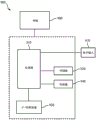
FIG. 1 shows a schematic diagram of a portion of a system operating in accordance with an embodiment of the present system;
FIG. 2A shows a side view illustration of a portion of a system operating in accordance with embodiments of the present system;
fig. 2B shows an exploded view illustration of a catheter assembly in accordance with an embodiment of the present system;
FIG. 3 shows a side view illustration of a portion operating in accordance with an embodiment of the present system;
FIG. 4 illustrates a functional flow diagram of a process that may be performed according to embodiments of the present system;
FIG. 5 shows a flow diagram of a process performed in accordance with embodiments of the present system;
FIG. 6 shows a screenshot of a User Interface (UI) illustrating a Planned Catheter Intersection (PCIP) superimposed on a corresponding 2D image slice of a reference dataset according to an embodiment of the present system;
fig. 7A shows a screenshot of a User Interface (UI) illustrating a 2D image slice of the pubic arch including a reference dataset according to an embodiment of the present system;
fig. 7B shows a UI illustrating 2D image slices after segmentation and selection of the pubic arch RA in accordance with embodiments of the present system;
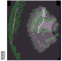
FIG. 8A shows a screenshot of an estimated intersection point of a catheter whose tip has not yet reached a current image plane superimposed on a current image, in accordance with an embodiment of the present system;
FIG. 8B shows a screenshot of an actual intersection of a catheter whose tip has not yet reached the current image plane superimposed on the current image, in accordance with an embodiment of the present system;
FIG. 8C shows a screenshot of an actual intersection of a catheter whose tip has passed through a current image plane superimposed on a current image, in accordance with an embodiment of the present system; and is
Fig. 9 shows a portion of a system in accordance with an embodiment of the present system.
Detailed Description
The following is a description of exemplary embodiments that will demonstrate the above noted features and advantages, as well as further ones, when considered in connection with the following drawings. In the following description, for purposes of explanation and not limitation, illustrative details are set forth, such as architectures, interfaces, techniques, element attributes, etc. However, it will be apparent to one of ordinary skill in the art that other embodiments that depart from these details would still be understood to be within the scope of the appended claims. Moreover, for the purpose of clarity, descriptions of well-known devices, circuits, tools, techniques and methods are omitted so as not to obscure the description of the present system. It is to be expressly understood that the drawings are for illustrative purposes and do not represent the entire scope of the present system. In the drawings, like reference numbers in different drawings may identify similar elements.
Fig. 1 shows a schematic diagram of a portion of a system 100 (referred to herein as system 100 for clarity) operating in accordance with an embodiment of the present system. The system 100 may include one or more of the following: a controller 102, a memory 106, a User Interface (UI)110, an actuator 112, a sensor 108, and an image acquisition part (IA) 104. One or more of controller 102, memory 106, User Interface (UI)110, actuator 112, sensor 108, and image acquisition portion (IA)104 may be integrated and/or remotely located from one another and/or may communicate with one another via any suitable wired and/or wireless communication method. For example, according to some embodiments, one or more of the controller 102, the memory 106, the User Interface (UI)110, the actuator 112, the sensor 108, and the image acquisition portion (IA)104 may communicate with each other via a dedicated bus and/or a network, as may be described elsewhere.
The controller 102 may control the overall operation of the system 100 and may include one or more logic devices, such as processors (e.g., microprocessors, etc.), switches, gates, and so forth.
The image acquisition section (IA)104 may include a two-dimensional (2D) imaging section 114 and a three-dimensional (3D) imaging section 116, which may capture 2D and/or 3D image information (typically image information), respectively. The 2D and 3D image information may then be provided to the controller 102 for further processing in a memory of the system, such as memory 106, and/or storage (e.g., in raw and/or processed form) for later use. For example, 3D image information may be acquired, processed, and then stored in memory 106, and 2D image information may be acquired in real-time and processed with the stored 3D image information in accordance with embodiments of the present system. The image acquisition portion 104 may comprise a 2D or 3D imaging device, which may be adapted for a corresponding imaging application. For example, when imaging the prostate, the image acquisition portion 104 may include an ultrasound probe, such as a transrectal ultrasound (TRUS) probe or the like.
According to still other embodiments, other imaging modalities with real-time imaging capabilities, such as MRI, may be provided for capturing at least some image information of a desired organ or portion thereof. For example, according to some embodiments, MR functional and anatomical imaging modalities may be provided and may be used to co-register functional data with anatomical features.
The 2D imaging portion 114 may include an ultrasound imaging portion, such as a TRUS probe or other suitable ultrasound probe, to capture image information using ultrasound methods or the like. According to some embodiments, the TRUS probe may include separate axial and/or sagittal arrays.
According to still other embodiments, the TRUS probe may capture 3D image information. For the sake of clarity, and not limitation, embodiments of the present system may employ a TRUS probe. However, according to still other embodiments, other types of ultrasound probes may be substituted for the TRUS probe. According to some embodiments, the TRUS probe may include an array to capture two-dimensional (2D) image information. Further, the array may be translated and/or rotated to capture three-dimensional (3D) image information. However, it is also envisioned that the array probe may include a two-dimensional matrix to capture 3D image information according to some embodiments. For example, the ultrasound probe may include any suitable array, such as a one-dimensional array, which may obtain image information to render a two-dimensional image. Further, according to some embodiments, the array may be translated and/or rotated to obtain a three-dimensional image. However, in still other embodiments, it is contemplated that the array may comprise a two-dimensional matrix array to obtain a three-dimensional image.
The 3D imaging portion 116 may include any suitable one or more 3D imaging portions, such as a 3D TRUS probe that may be similar or identical to the TRUS probe of the 2D imaging portion 114. However, the 3D imaging portion may include an image capture device, such as a TRUS probe that may capture 3D information. For example, the TRUS probe may include a 2D TRUS probe that may be translated and/or rotated to acquire a 3D volume. The 3D imaging portion 116 can provide the captured image information to the controller 102, and the controller 102 can reconstruct and then store the reconstructed image information in a memory of the system (such as the memory 106) for later use. Thus, according to some embodiments, the 3D TRUS probe may be provided with a rotation and/or translation stepper, which may encode the spatial position of the 2D TRUS probe, which may provide a reconstruction of the acquired 3D volume.
According to some embodiments, it is contemplated that the 3D imaging portion 116 may include any suitable 3D imaging portion or portions, such as an ultrasound imaging system, a Magnetic Resonance (MR) imaging (MRI) imaging portion, and/or a Computed Tomography (CT) imaging system. According to still other embodiments, image information obtained from one or more imaging sources (such as a TRUS probe and/or MRI) may be registered to provide a composite image, if desired.
The sensors 108 may include one or more sensors that may detect the position and/or orientation of one or more desired portions of the system 100, such as the position of an image capture device (e.g., a TRUS probe or other image processor (s)), a grid template, a catheter (e.g., an implanted catheter or portion thereof, such as a distal end), a patient (or portion of a patient), etc., relative to a desired frame of reference and/or coordinate system (e.g., an x, y, z coordinate system). The sensors 108 may then form corresponding sensor information and provide the sensor information to the controller 102 for further processing. For example, the sensor 108 and/or the controller 102 may determine the position and/or orientation of the TRUS probe 114 as it acquires images using any suitable method or methods, such as Electromagnetic (EM) and/or optical tracking methods (e.g., Optical Shape Sampling (OSS)). According to some embodiments, the determined position and/or orientation of the TRUS probe 114 may then be associated with corresponding image information. For example, the position and/or orientation of the TRUS probe may be obtained using an Electromagnetic (EM) Field Generator (FG) (EMFG) and/or one or more EM reference sensors, which may form corresponding information indicative of the position of the TRUS probe 114.
For example, fig. 2A shows a side view illustration of a portion of a system 200 operating in accordance with embodiments of the present system. The system 200 may be similar to the system 100 and may include an image acquisition portion 204, a sensor 208, and a controller 202, which may be similar to the image acquisition portion 104, the sensor 108, and the controller 102, respectively, of the system 100.
The system 200 may also include one or more catheter assemblies 222 (hereinafter catheters, for clarity) that may have proximal and distal ends 222P and 222D, respectively, and that may be supported and/or steered (at least partially) by the grid template 220. Without limitation, since one or more of the conduits 222 may be similar to one another, for clarity only a single conduit 222 may be discussed herein. Further, if desired, the catheter 222 may be steerable by an actuator controlled by the controller 202 and/or by a user. Similarly, if desired, the catheter 222 may be withdrawn from insertion and/or through an actuator controlled by the controller 202 and/or by a user. The catheter 222 may be shaped and sized such that it may be inserted into a desired object of interest (OOI), such as the prostate 209 of the patient 201, such that the distal end of the corresponding catheter 222D may be located within the OOI while the proximal end 222P of the catheter may be located outside the OOI during use. Without limitation, it is also contemplated that one or more of the conduits 222 may be the same or different from one another, if desired.
Fig. 2B shows an exploded view illustration of a conduit 222 in accordance with embodiments of the present system. Referring to fig. 2B, the catheter 222 may be formed from an assembly including one or more of the body 236 and the obturator 232. The body 236 may include proximal and distal openings 238 and 240, respectively, and a lumen 234 adapted to receive the obturator 232 positioned between the proximal and distal openings 238 and 240, respectively.
The catheter 222 may include a tracking element, such as one or more EM sensors 230 (e.g., EM tracking sensors), which may be tracked by the controllers 102, 202 to determine the position and/or orientation of the one or more EM sensors 230 and/or the portions attached thereto. However, in still other embodiments, the tracking method may include any suitable tracking method, such as an optical sensing (e.g., optical shape sensing) method and/or the like.
Although the EM sensors 230 are shown as being attached to one end (e.g., the distal end) of the obturator 236, it is also contemplated that one or more EM sensors 230 may be attached to the body 236, such as at the tip of the body 236. In any event, the EM sensor 230 may be referred to as a tracking element. Further, in still other embodiments, multiple tracking elements, such as EM sensors 230, may be positioned at various locations on the body 236 of the catheter 222 and/or the obturator 232, such as at a distal end thereof.
According to some embodiments, controller 202 may track (e.g., spatially track) the tracking element using any suitable method, such as an EM method, and may determine a position (e.g., a position and/or an orientation) of the tracking element and/or a portion(s) of the catheter in close proximity to the tracking element. For example, during use, such as during an HDR brachytherapy procedure performed in accordance with embodiments of the present system, the controller 202 may track the tip (e.g., distal end) of the catheter 222 by determining the position and/or orientation of a tracking element positioned at the tip (e.g., distal end) of the distal end of the corresponding obturator 232 of the catheter 222. According to some embodiments, the controller 202 may detect entry of the catheter 222 into the grid template. Controller 202 may also identify catheter 222 (e.g., using an Identification (ID) of the catheter) and/or may determine the array location within the grid template. The array position may provide the coordinates of the catheter 222 in a desired plane (e.g., an x-y plane corresponding to the surface of a grid template, where the surface of the grid corresponds to z-0). As the catheter 222 passes through the grid template, its position (e.g., column, row) within the grid template may be determined. According to some embodiments, the grid template may be optional there. Accordingly, a user (e.g., a physician, clinician, etc.) may perform implantation of the prostate by manipulating one or more of the catheters 222 with bare hands.
The obturator 232 may be shaped and sized so as to be slidably insertable into and/or withdrawable from the lumen 234 of the body 236 through one or more of the proximal and/or distal openings 238, 240, respectively. However, according to embodiments of the present system, when performing an HDR procedure, the distal opening 249 may be sealed using any suitable method (such as by using an end cap located at the distal opening 240) in order to seal the distal opening 240. This may prevent the accidental deposition of HDR radioactive sources (e.g., seeds) into the patient's body. Accordingly, it will be assumed that the obturator 232 may be inserted into the lumen 234 and/or withdrawn from the lumen 234 via other openings (e.g., unsealed openings) of the lumen 234, such as the proximal opening 238 of the body 236. The end cap at the distal opening may be shaped and sized (e.g., pointed, etc.) so that the catheter may easily penetrate tissue during insertion.
If desired, a retaining mechanism may be provided for locking the obturator 232 in position relative to the body 236. For example, the retention mechanism may include any suitable retention mechanism, such as a detent 242 that may engage a portion of the body 236 to secure the obturator 232 to the body 236 for use, in accordance with embodiments of the present system. However, according to still other embodiments, the retention mechanism may comprise any suitable friction, screw, or latch type retention mechanism or the like. For example, according to some embodiments, the retention mechanism may include one or more wave features (e.g., which may extend about an outer perimeter of the obturator 232) to frictionally engage an interior of the lumen 234 of the body 236 when the obturator 232 is fully inserted into the body 236. This may prevent movement of the obturator 232 relative to the body 236 when the combination is manipulated. However, these portions may be separated from one another when a removal force is applied between the obturator 232 and the body 236.
As discussed above, the obturator 232 may have a tracking element (such as the EM sensor 230) positioned for tracking the position of the corresponding tip. Thus, during use, the controller 102, 202 may determine the position and/or orientation of the tip of the obturator 232 by determining the position and/or orientation of a corresponding tracking element (such as the EM sensor 230 positioned at a corresponding end of the obturator 232).
Referring back to fig. 2A, one or more of the catheters 222 may include a steering mechanism such that the catheter 222 may be actively steered by the user and/or the controller 202. For example, one or more of the catheters 222 may include an actuator that may actively steer the catheter 222 or a portion thereof (such as the distal end 222D) under the control of the user and/or the controller 102, 202. For example, according to some embodiments, the controller 202 may control the actuators of one or more of the catheters 222 to actively steer (or in close proximity to) the distal portion of the corresponding catheter 222 to a desired position. The catheter 222 may be shaped and/or sized to be implanted within the prostate 209 of the patient 201.
The image acquisition portion 204 may include an ultrasound probe, such as a TRUS probe 224, which may perform one or more scans and provide corresponding image information (e.g., 2D or 3D image information) to the controller 202 for further processing. The image information may also include information about the location of portions of one or more of the catheters 222. For example, during implantation of one or more of the catheters 222, the TRUS probe 224 may provide transrectal ultrasound image information that may be provided to the controller 202 for further processing and may include information related to the position of one or more of the catheters or portions thereof (such as the distal end 222D of the corresponding catheter 222). In accordance with embodiments of the present system, the controller 202 may then determine guidance information, such as catheter guidance information.
In accordance with embodiments of the present system, the sensors 208 may detect operating parameters, positions, and/or orientations (e.g., relative to a desired reference point, reference plane, coordinates, etc.) of one or more portions of the system 200, such as the position of the catheter 222, the grid template 220, and/or the TRUS probe 224, and form corresponding sensor information that may be provided to the controller 202 for further processing. In accordance with embodiments of the present system, the sensors may track the position and/or orientation of the grid template 220, the catheter position and/or orientation relative to each other and/or relative to the grid template 220, and/or the position and/or orientation of the TRUS probe 224. According to some embodiments, the sensors 208 may include EM and/or optical tracking sensors.
According to embodiments of the present system, the controller 202 may process the image information and render the composite image on a display of the system for convenience to a user (e.g., clinician, doctor, etc.). According to embodiments of the present system, the controller 202 may also determine guidance information that may be determined by the controller 202. The guidance information may include information related to an actual and/or desired (e.g., estimated) position of one or more of the catheters 222 and/or portions thereof (e.g., distal ends of one or more of the catheters 222) relative to, for example, a fixed point, a plane (e.g., a current live image plane), coordinates, portions of the system 200 (e.g., a grid template, etc.), and/or an object of interest, such as the prostate 209. The guidance information may also include actual and/or desired position(s) with respect to the TRUS probe 224 or portions thereof, e.g., with respect to a fixed point, plane (e.g., along the z-axis), or object of interest (OOI, such as the prostate, etc.). For example, the controller 202 may determine guidance information, such as probe guidance information (as opposed to catheter guidance information) that may indicate a desired position of the TRUS probe 224 along the z-axis, and draw such information on a display of the system to inform the user of the desired position. However, in still other embodiments, it is contemplated that the controller 202 may control an actuator of the system (e.g., a probe position actuator) to change the position of the TRUS probe 224 according to desired probe position information. Similarly, the controller 202 may determine catheter position information and control actuators of the system (e.g., actuators of the catheter and/or the mesh template) to change the position of one or more of the catheters 222 (or portions thereof) in accordance with the catheter position information. It is also contemplated that, for convenience of the user, the controller 202 may draw information related to catheter position information on a display of the system. If desired, the probe and/or catheter position information may be determined and/or updated in real-time and may be plotted on a user interface of the system for user convenience. The catheter guidance information may include a desired location of one or more of the catheters. The probe position actuator may form part of a TRUS probe positioning system that may position (e.g., using a stepper or the like, which may include a stepper motor) the TRUS probe 224 at a desired position relative to one or more coordinates under the control of the controller 202.
A grid template positioning mechanism may be provided to position the grid template 220 at a desired location and/or orientation. For example, fig. 3 shows a side view illustration of a portion of a system 300 operating in accordance with embodiments of the present system. HDR system 300 may be similar to HDR systems 100 and/or 200 and may include a catheter 322 and a trellis template 320, which may be similar to catheter 222 and trellis template 220 of fig. 2A, respectively. The grid template 320 may include a plurality of channels 321 arranged in an array and may be parallel to each other. The channel 321 may be shaped and/or sized to receive the catheter 322, through which the catheter 322 may pass, and which may support and/or guide the catheter 322. Thus, the grid template 320 may provide for placement of the catheter within the prostate 307 of the patient 301.
The grid template positioning mechanism may adjust the position and/or orientation of the grid template 320 about (e.g., about and/or along) one or more axes. According to some embodiments, the grid template positioning mechanism may be adjusted by a user (e.g., a clinician, etc.) to adjust the position and/or orientation of the grid template 320 about one or more axes. However, in still other embodiments, it is contemplated that the grid template positioning mechanism may include at least one actuator that may adjust the position and/or orientation of the grid template 320 about one or more axes under the control of the controller of the system 300. Further, the grid template positioning mechanism may include sensors that may provide information related to the position and/or orientation of the grid template 320 to the controller for further processing.
Referring back to fig. 1, the actuator 112 may include one or more actuators, which may be controlled by the controller 102. According to embodiments of the present system, the actuator 112 may include, for example, a radial and/or linear motor (e.g., a micro-motor (MEM), an electro-active polymer (EAP), a Shape Memory Alloy (SMA), etc.) that may output a desired force and/or displacement under the control of the controller 102.
To facilitate the user, the User Interface (UI)110 may include any suitable user interface that can draw information. For example, the User Interface (UI)110 may include a display (e.g., a touch screen display, etc.), speakers, haptic devices, and the like. Thus, the controller 102 may render the information by providing the information to the User Interface (UI)110, which the User Interface (UI)110 may then visually, audibly, and/or tactilely output the information provided thereto. The User Interface (UI)110 may also include a user input device with which a user may enter information. For example, a touch screen display may receive information entered by a user, such as a user selection or the like. According to still other embodiments, the user input device may comprise any other user input device with which a user may enter information (such as a mouse, touchpad, trackball, light pen, etc.).
It is also envisioned that embodiments of the present system may provide a system and method for automatically segmenting the boundary of the prostate on a 2D image (axial or sagittal slice, e.g., a current slice such as a 2D image slice) that may be rendered in real time on a display of the system. Thus, the clinician may be provided with quantitative knowledge that may enhance these determined boundaries on the current slice of the catheterization procedure.
Fig. 4 illustrates a functional flow diagram of a process 400 that may be performed in accordance with embodiments of the present system. The process 400 may be used during an interventional procedure and may provide real-time guidance to a clinician or catheter control system. Process 400 may be performed using one or more computers in communication over a network and from which information may be obtained and/or stored using one or more memories that are local and/or remote to each other. Process 400 may include one or more of the following actions. In some embodiments, the actions of process 400 may be performed using one or more suitable medical imaging systems, such as an ultrasound imaging system operating in accordance with embodiments of the present system. Further, if desired, one or more of these acts may be combined and/or separated into sub-acts. Further, depending on the settings, one or more of these actions may be skipped. In operation, the process may begin during act 401 and then proceed to act 403.
During act 403, the process may acquire a 3D reference image dataset of a volume of interest (VOI). The 3D reference image dataset (hereinafter referred to as reference dataset) may comprise a plurality (e.g. N, where N is an integer) of 2D image slices of a VOI in which a desired object of interest (OOI) may be located, such as a prostate of a patient. Thus, the reference data set may comprise N image slices of a desired OOI (such as the prostate). These N image slices may be taken in one or more image planes. For example, according to some embodiments, the image slices may be in a sagittal plane, while in other embodiments, the image slices may be in a transverse or one or more other planes. For the sake of clarity, rather than referring to OOI throughout the description of process 400, reference will be made to the prostate. However, without limitation, it should be understood that the prostate may be replaced with reference to other OOIs, if desired. For example, it is contemplated that other organs and/or portions thereof may be substituted for the prostate, if desired. However, for the sake of clarity, reference is made to the prostate.
The reference data set may be acquired using any suitable ultrasound imaging apparatus, such as a TRUS probe or the like. However, in still other embodiments, other types of imaging devices are also contemplated and may be used with and/or in place of a TRUS probe. During acquisition of the reference data set, an imaging device (e.g., a TRUS probe) may be tracked (e.g., by sensors of the system) such that a position and/or orientation of TRUS may be determined and associated with each corresponding 2D image slice acquired. These image slices may then be superimposed to form a 3D reference data set.
According to some embodiments, it is contemplated that the 3D reference dataset and/or portions thereof may be acquired using one or more imaging methods, such as MRI, CT, MR, Positron Emission Tomography (PET), and/or ultrasound imaging methods. If desired, acquired image information that may be obtained from multiple image acquisition sources may be registered to form all and/or a portion of a 3D reference data set. However, for the sake of clarity, it will be assumed that the 3D reference data set was acquired using the TRUS probe described herein. Further, while embodiments of the present system may be described with respect to anatomical imaging and data methods, it should be understood that some of the embodiment imaging methods described herein may be similarly operated using functional imaging methods. For example, if desired, embodiments of the present system may translate functional information in real-time to provide real-time guidance.
The TRUS probe may be positioned at a desired position and/or orientation relative to the patient. For example, fig. 2A shows the placement of the TRUS probe 224 relative to the prostate 209 of the patient 201 so that it can acquire a reference data set. The TRUS probe 224 may be tracked (e.g., along and/or about the z-axis) during acquisition of the reference data set such that the position and/or orientation of the TRUS probe 224 during acquisition of each 2D slice may be associated with the corresponding 2D slice of the 3D reference image data set according to the position information. More specifically, the process may track the position and/or orientation of the TRUS probe, form corresponding position information, and associate the position information with a corresponding 2D image slice of a reference data set (such as the reference data set shown in fig. 5 of a flow chart 500 illustrating a process performed in accordance with embodiments of the present system).
More specifically, fig. 5 shows a three-dimensional (3D) reference dataset 540, which may comprise a pre-acquired 3D image dataset having a plurality (e.g., a selected number such as N) of two-dimensional (2D) image slices (e.g., 2D slices), which are taken from a VOI (which may include an OOI), acquired prior to catheter insertion into a patient, and stored in memory for retrieval and reference during acquisition of further images using a catheter inserted into the patient. After completing act 403, the process may continue to act 405.
During act 405, the process may segment the reference data set using any suitable segmentation method or methods, which may include automatic and/or manual methods (e.g., using user input). For example, a suitable segmentation method may use Uronav operating in accordance with embodiments of the present systemTMFusion biopsy System (Using Uronav)TMBiopsy platforms are available; invivo, Gainesville, FL, USA) and may be performed to segment the 3D image information in the reference data set and form corresponding Segmentation Information (SI) which may define, for example, boundaries of portions within the VOI, such as boundaries of the prostate for 2D image slices of the 3D reference data set. More specifically, embodiments of the present system may perform image intensity-based segmentation in a lateral slice of the mid-gland and then use this segmentation as an initialization to define contours superior and inferior to that slice. Thus, the boundary of the prostate may be defined for one or more of the image slices of the reference dataset and may be represented as a Curvilinear Boundary Surface (CBS) which may represent the contour of the prostate. More specifically, each of a plurality of 2D image slices (e.g., 2D image slices) of the reference data set may be segmented to form Segmentation Information (SI) that may define a CBS of the prostate. For example, referring to fig. 5, the CBS 545 may define the boundary of the prostate for each of a plurality (or selected ones) of the 2D image slices of the reference data set 540. The process may associate an SI (which may include information related to CBS) with each corresponding 2D image slice of the 3D reference data set and may store this information in a memory of the system for later use. Thus, the reference data set may comprise associated tracking and/or segmentation information.
According to some embodiments, a finite element analysis method (FEA) may be used, which utilizes a biomechanical model of tissue response to delineate biological tissue (such as organs and/or glands) in order to segment the reference data set. Thus, it is envisioned that some embodiments may employ the FEA method to delineate a prostate within a 3D volume. Furthermore, according to still other embodiments, gradient algorithms (e.g., as provided by MIM software corporation of cleveland, ohio) may be used to segment tissue and may define edges in addition to segmentation based on image intensity. It is also envisioned that some embodiments may employ atlas-based algorithms that use deformable registration to modify and apply population-based contours to the current dataset. After completing act 405, the process may continue with act 406.
During act 406, the process may define a Location Constraint (LC), such as at least one or more of: a Planned Catheter Intersection Point (PCIP), a Peripheral Boundary (PB) of the OOI, and a Restricted Area (RA). One or more of the location constraints may be defined by the system and/or the user. For example, according to some embodiments, the process may determine PCIP based on at least one or more of RA and/or CBS. In still other embodiments, the user may define one or more of PCIP and/or RA. According to still other embodiments, RA may be defined by a user and PCIP may be optionally defined. Further, according to some embodiments, one or more of the location constraints may be determined based on one or more other location constraints. For example, PCIP may be determined based on a restricted area, and vice versa.
With respect to PCIP, the PCIP for one or more catheters of the system may be defined relative to the CBS of the prostate, as may be set forth in the segmented data set. More specifically, the process may determine a PCIP for one or more of the catheters relative to a boundary region (e.g., a peripheral boundary region) of the prostate of one or more corresponding 2D image slices of the reference dataset, as may be defined by the CBS. The PCIP may be associated with a corresponding 2D image slice and stored in a memory of the system for later use. More specifically, the PCIPs may be determined such that when the distal ends of the catheters are at their corresponding PCIPs, the distal ends of one or more of the catheters are expected to be in a boundary region of the prostate (e.g., as defined by the CBS that defines the peripheral boundary of the prostate). Further, according to some embodiments, the PCIP may also be determined according to a Restricted Area (RA), as may be described below, such that the conduits do not intersect or otherwise contact the RA, as will be described below. According to some embodiments, the process may also determine the PCIP based at least in part on the RA. For example, the procedure may avoid PCIP where its location may require a catheter to pass through the RA. Thus, the location of the PCIP may be based at least in part on the RA, which may be defined in the reference data set.
PCIP may generally define a point where a portion of the catheter, such as a distal end (e.g., a tracked distal end) of one or more of the catheters, is estimated (e.g., expected or calculated) to intersect an image plane of the 2D image slice and may extend only beyond a location of the image plane (as may be defined by the system and/or user) by a threshold extension value (e.g., 0.5mm, etc.). The process may perform this action using any suitable placement method or methods.
The process may use any suitable method to draw a user interface that may show the PCIP for one or more catheters. For example, according to some embodiments, the process may represent the catheter using dots or other graphical representations.
According to some embodiments, the process may determine a catheter range, which may generally be the difference between the actual position of the catheter (as may be measured at the tip of the catheter) and the current image plane or PCIP, and provide a representation (e.g., an alpha/numeric and/or graphical representation) of the results of the comparison for the convenience of the user. The conduit range will be discussed further with respect to act 427.
Returning to the reference location constraints, fig. 6 shows a screenshot of a User Interface (UI)600 illustrating location constraints such as PCIP664 superimposed on a corresponding 2D image slice 662 of the reference data set, in accordance with an embodiment of the present system. CBS645 may be defined by the process and, thus, may be similar to CBS 545 of fig. 5. However, in fig. 6, a PCIP664 and a Restricted Area (RA) are shown. The RA may be illustrated by lines 662-1 through 662-M (typically 662-x superimposed on corresponding 2D image slices 662 of the 3D reference data set), where RA's 662-1 and 662-2 are shown in FIG. 6, and may define regions that neither catheter should pass through. RA may be distinguished as regions, as will be discussed below. The system (e.g., during segmentation) and/or the user may define the RA. RA may be represented by any suitable shape, such as a line that may be set forth as an area of RA (e.g., on one side of the line), and/or by using a closed line within which RA may be located (e.g., a circle, polygon, ellipse, other custom shape, etc.) (as will be described below with reference to fig. 7A and 7B). Further, fig. 6 may include a grid pattern (e.g., dots) that may be marked 668 such that a user may easily determine the location (e.g., column, row) of the catheter in the corresponding grid template array.
According to some embodiments, the segmentation process is operable to set the RA within the reference data set in accordance with a set of RAs for one or more of the image slices. For example, if the user sets the RA in one image slice that defines the boundary of the urethra (e.g., the urethra region), the process may automatically detect this and may determine the RA for the urethra region in the other 2D image slices of the 3D reference data set. Thus, the user may set an RA in an image slice of the reference data set (e.g., an RA for a region), and may set the RA throughout the reference data set or a portion thereof (e.g., an RA for a corresponding region).
In general, travel through the RA may be undesirable (e.g., travel of a catheter near the urethra or bladder (shown as 207 and 308 in fig. 2-3) should be avoided so as not to cause physical damage to these structures) or impossible (e.g., travel through bone (such as the pubic arch) may not be possible unless drilled).
In accordance with embodiments of the present system, one or more types of RA regions may be defined as shown in table 1 below. The process may provide a user with a user interface defining the RA area and may then save information relating to the defined RA area as RA information in a memory of the system. Although only three regions are shown, other regions may be defined and stored in the memory of the system for later use. Furthermore, different RA regions may be defined for different flows. For example, other types of HDR flows may each have a defined corresponding RA region, which may for example be different from the RA regions of table 1.
TABLE 1

One or more of the RAs (e.g., RA regions) may be segmented automatically by the process during and/or after segmentation by the user. For example, according to some embodiments, the urethral region may be selected by the procedure during segmentation (see, e.g., 662-1 of fig. 6), while the pubic arch region may be selected manually. For example, fig. 7A shows a screenshot of a User Interface (UI)700A illustrating a 2D image slice including a pubic arch of a reference dataset according to an embodiment of the present system; and fig. 7B shows a UI 700B as UI 700A illustrating the 2D image slice after segmentation and selection of the pubic arch RA according to embodiments of the present system. Referring to fig. 7A, the location of the pubic arch is illustrated by the path shown by dashed line 703 and pointed by arrow 705. This path (e.g., path 703) may be segmented automatically by the process (if desired) or may be set by the user. Referring to fig. 7B, the process may provide the user with the option to enter and/or edit the pubic line 707 that may define the pubic arch. The procedure may then set the entire working space above (e.g., before) the pubic arch line 707 to the pubic arch RA. The procedure may then highlight (e.g., via crosshairs) the pubic arch RA (region) using any suitable method (such as by inserting crosshairs 709 into the pubic arch RA). The user may then modify the location of the pubic arch line 707 in real time (if desired), and thus, the process may update the pubic arch RA. However, according to some embodiments, the process may automatically form a pubic arch RA during segmentation of the reference data set, and may then render information related to the pubic arch RA such that the user may approve, edit, and/or reject the pubic arch RA. Although a pubic arch RA is discussed, the process may perform similar actions to select other RAs, as may be desired.
Referring back to PCIP, the process may determine and/or optimize PCIP from RA, as may be set by the system and/or the user. For example, for user convenience, after the PCIP is determined, the process may plot the information. The user may then set an RA, and the process may then optimize the PCIP according to the set RA. Thus, if the PCIP is not nearby (e.g., urethra), the user may determine that urethra RA does not need to be set. This may save time, if desired. However, according to some embodiments, it is contemplated that PCIPS may be automatically determined and RA set without user intervention with respect to the reference data set.
After completing act 406, the process may continue to act 407, during act 407, the TRUS probe may be positioned at a desired location of a catheterization procedure in which one or more of the plurality of catheters may be inserted into the prostate. The TRUS probe may be automatically positioned to a default position and/or orientation by a controller of the procedure (such as with a lateral/axial array set to image the mid-gland region of the patient's prostate) or may be manually positioned by a user (such as a clinician).
For example, according to some embodiments, after determining that the reference data set has been acquired, the process may render information that informs the user to place the TRUS probe in place (e.g., a starting position) so that the TRUS probe can acquire an image of the prostate, as will be discussed below. However, according to still other embodiments, the process may control the actuators of the system to position the TRUS probe at a desired position and/or orientation, such as a default starting position. The default starting position may be selected from a default value obtained from a memory of the system and/or determined from a starting position of the TRUS probe when the reference data set was acquired. According to still other embodiments, the process may request that the user position the TRUS probe in a desired location and may then automatically control the control position and/or orientation of the TRUS probe. After completing act 407, the process may continue to act 409.
During act 409, the process may capture a current image (e.g., in 2D) of the VOI including the prostate in real-time, and may form corresponding image information. Thus, the current image may be considered a live image. The current image may be updated at a desired frame rate (e.g., 15 frames per second in this embodiment). According to still other embodiments, the current image may be updated (e.g., by repeating act 409) after one or more acts in the current process are completed. The current image may depend on the position of the TRUS probe. The position of the TRUS probe may be based on the user's selection (if desired), and may include, for example, a mid-gland location.
According to still other embodiments, the current image may be updated when a particular condition is determined to occur, such as when the position of the TRUS probe is changed, upon detecting a request by a user, upon detecting insertion of a catheter or subset of catheters into the prostate, or upon detecting a user or system defined condition, such as detecting that motion advancing the catheter has stopped for a threshold period of time (e.g., 5 seconds) or has been advanced in a desired direction by a particular amount, as may be set by a user and/or system.
Referring to fig. 5, the current image may include a live 2DTRUS image 548 that may be acquired by the TRUS probe and may include the prostate.
According to other embodiments, it is envisioned that a current image (e.g., a live or in-flow image) may be acquired as 3D image information using a 3D probe. Thus, the 3D image information may then be processed similarly to the 2D image: which may be displayed using surface or volume rendering or using one or more 2D sections through a 3D volume. Furthermore, it is also contemplated that the segmented reference dataset may be used to initialize the segmentation in the current image, which enables real-time segmentation and visualization of the organ boundaries and/or any RA in the procedure, if desired. The process may also select a default image slice from the current image and set that slice as the current image, if desired.
According to still other embodiments, user and/or system defined conditions may be set by a user and/or system as desired using, for example, a setup table formed and/or drawn by a process. Thus, the user may interact with the settings table to set/reset the settings table to define user-defined conditions, if desired. Thereafter, the setting table may be correspondingly updated and stored in the memory of the system for later use. The process may then obtain a settings table from the memory of the system, and when a setting as defined in the settings table is determined to occur, the process may perform a corresponding action, such as updating the current image.
The process may also track the TRUS probe to determine its position and/or orientation and form corresponding position information, which may include position and/or orientation information of the TRUS probe, and may associate the TRUS probe position information with the current image. In other words, the process may correlate location information, which may include information related to the position and/or orientation of the TRUS probe at the time the current image was acquired, and correlate that information with the corresponding current image. According to some embodiments, the current image and associated location information may be stored in a memory of the system for further processing, if desired.
According to some embodiments, the process may provide the user with the option of selecting an image plane (such as in an axial and/or sagittal image plane) in which to view the current image. The process may then segment the 3D image according to the selected image plane setting. For example, if it is determined that the user has selected a sagittal image plane, the process may segment the reference data set in the same plane. Similarly, if it is determined that the user has selected an axial image plane, the process may segment the reference image dataset in the same plane. However, according to some embodiments, the process may segment the reference data sets in the two planes and may then select the image in the plane corresponding to the plane selected for the current image. Thus, if the current image is selected within the axial plane, the process may obtain a segmented image corresponding to the axial plane of the reference image dataset. Thus, the current image may be obtained in the same reference plane as the image slice. After completing act 409, the process may continue to act 411.
During act 411, the process may initialize an image registration process. Thus, the process may select at least one image slice (e.g., a 2D image slice) of the reference dataset that is determined to be the best match (e.g., the closest match) to the current image. In other words, the process may estimate at least one of the (2D) image slice(s) (e.g., in a corresponding axial or sagittal plane) from the reference dataset that best matches the current image according to the location information.
The selected image slice may be selected from the reference data set and may have a position that most closely matches the position of the current image. Thus, the process may determine the position of the current image along a predetermined axis (e.g., a z-axis as determined by the position of the TRUS probe) (e.g., based on the position of the TRUS probe), and may then select an image slice from among the image slices of the reference dataset that correspond to (or most closely correspond to) the position of the current image (e.g., along the same axis and within the same plane). The selected image slice may be considered the best matching image slice by location.
To increase robustness, the process may use any suitable method, such as using any suitable image analysis method, to determine whether the selected image slice most closely matches the current image. If the selected image slice is determined not to be the closest match, the process may select the image slice from the reference dataset that most closely matches (e.g., by a ± ns slice, where ns is an integer) the current image. Further, when performing image analysis, the process may take into account that the current image may include interventional tools (such as catheters, etc.) other than the prostate. Thus, the process may filter the interventional tool when comparing the current image to the image slices of the reference data set. According to some embodiments, the process may select two closest image slices from the reference dataset that most closely match the current image, and may then form the selected image slices into a composite image based on the two selected closest matching slices.
With respect to patient motion relative to the TRUS probe between the acquisition of the reference data set and the current image, little motion is desired and workflow affecting the current process is not desired. More specifically, since the TRUS probe can fit closely within the patient's rectum, little relative probe motion is desired in the lateral and/or a-P directions. This movement may generally be considered unimportant.
The process may use any suitable image matching method (such as UroNav operated by embodiments of the present system)TMThe method provided by the biopsy platform) performs the action. This is illustrated with reference to act 542 of FIG. 5.
According to some embodiments, to increase robustness, the process may select at least two image slices (e.g., an image set) from a reference data set that most closely matches the current image ± ns slices (where ns is an integer, such as 1, and may be set by a user and/or system) rather than selecting a single image slice from the reference data set. This procedure may be used if the reference data set is acquired using the same slice orientation as the current image. Thus, the location information may be used to select a range of image slices (e.g., an image set) from the reference data set by location. The process may then form a composite image based on the set of images and set the composite image as the selected image. The process may also determine the CBS for the image. In still other embodiments, the process may apply image matching to select one or more images from a set and collection of images. The process may then form a composite image (e.g., selecting two or more images from the set, as discussed above). The process may also use any suitable method to determine the corresponding location for the composite image (e.g., via interpolation, etc.). Thus, for example, if the process forms a composite image based on two images from a reference data set correspondingly positioned at ± 1mm (along the z-axis), the process may determine that the position for the composite image is 0mm (along the z-axis). As discussed above, multiple images may be used to overcome any possible relative patient-probe motion, if desired. The process may store the selected image slice (if a composite image) associated with the reference data set for later use. The process may also determine a CBS for the composite image, as discussed above, and may store the CBS associated with the composite image in the reference dataset for later use. The composite image may be referred to as a pseudo image.
In still other embodiments, the selected image slice (e.g., 2D image slice) may be selected from the reference dataset as the image slice determined to best fit (e.g., most closely fit) the current image using image analysis-only methods, rather than by location, as discussed above, if desired.
Furthermore, according to still other embodiments, the reference dataset may comprise any 3D dataset and may even not comprise well-defined image slices or may comprise image slices which may have a different orientation than the current image. Thus, in this case, the process may determine a volume slab (slab) within a reference image dataset (e.g., of any suitable thickness, such as 5mm or 10mm thickness, etc.) within which the current (e.g., live) 2D image may be located. The 2D cross-section at any location within the slab can then be used to initialize the live 2D segmentation, and some measure of "goodness of segmentation" can be used to select the best 2D segmentation. The above-described intra-slab segmentation may be used to constrain the current 2D segmentation, if desired.
After completing act 411, the process may continue to act 413.
During act 413, the process may link the location of the current image with the location of the selected slice of the reference data set. In other words, the process may link the position information corresponding to the current image (e.g., the position and/or orientation of the TRUS probe) with the corresponding position of the selected image slice (or at least one image slice) of the reference data set. Once the position information is linked, images (e.g., current images) acquired in real-time at a particular position and/or orientation (of the TRUS probe) may be linked to images in the reference dataset having the same (or similar) position/orientation. The process may continuously update the linked location in real time, if desired.
According to some embodiments, the process may link the location of the current image with the location of the selected slice of the reference data set using any suitable one or more methods. For example, the process may perform an initial linking, as described above. The process may then use image recognition methods to identify features of the prostate in the current image and select a corresponding image (e.g., the selected image) in the reference dataset. The location of the selected image may then be linked to the location of the current image. This may explain the deformation that may occur when the catheter is inserted into the prostate. For example, when inserting a subject (such as a catheter) into the prostate, the catheter may advantageously dislocate the prostate by at least several centimeters and/or change the shape of the prostate. For example, the catheter may lengthen the prostate, and as such, the slice coordinates may not have a one-to-one correspondence. Thus, embodiments of the present system may employ an image-based approach (e.g., which may employ an image registration approach, if desired) to continuously link the location of the current image with a selected reference image from a reference data set, if desired.
After completing act 413, the process may continue to act 415.
During act 415, the process may obtain a CBS corresponding to the selected image from the reference data set. Thus, the process may obtain the CBS from the reference dataset as the CBS for the selected image slice. The CBS may be referred to as a selected CBS. Since the selected image slice may be considered to be the closest fit to the current image, the CBS may also be considered to be the closest fit (e.g., closest match) CBS to the current image.
According to some embodiments, the process may perform an image registration process to register selected image slices from a reference dataset onto a current image (e.g., a live image). This image registration process may be performed using any suitable image registration method, such as an automated registration algorithm, to register the images, as disclosed in applicant's prior co-pending application No. pct/IB2013/059989 entitled "Assisting Apparatus for Assisting in Performing a brachytherpy" that may be filed on 8.11.2013 and published as WO2014/091330 a1 on 19.2014.6.19, the contents of each of which are incorporated herein by reference.
After completing act 415, the process may continue to act 416, where the process may determine a position and/or orientation for the grid template. According to some embodiments, the position and/or orientation of the grid template may be set by the system and/or a user. For example, according to some embodiments, the position and/or orientation of the grid template may be set by a user. According to still other embodiments, the system may determine the position and/or orientation of the grid template and may therefore plot this information in order to facilitate a user who may then set the position and/or orientation of the grid template. In still other embodiments, the system may control actuators to set the position and/or orientation of the grid template, as may be discussed elsewhere.
According to some embodiments, the process may determine the location and/or orientation of the grid template from one or more of the location constraints. For example, according to some embodiments, the process may determine the location and/or orientation of the grid template according to one or more of the location constraints so that one or more of the conduits may intersect its PCIP and/or not intersect the PA, as may be desired by the user. Any suitable method may be used to determine the position and/or orientation of the grid template.
According to some embodiments, the process may determine the location and/or orientation (hereinafter referred to as position) of the grid template based at least in part on one or more of a location constraint (e.g., PCIP and/or RA), the location and/or orientation of the TRUS probe, the current image, and/or a reference dataset using any suitable method, such as geometric methods operating in accordance with embodiments of the present system. For example, when the TRUS probe has been previously linked (e.g., during act 413), its position relative to one or more of the current image and the reference dataset may be determined. The process may then use one or more position constraints (such as PCIPs and/or RAs) to determine the position and/or orientation of the mesh template such that projected trajectories of one or more of the catheters passing through and/or extending from the mesh template intersect at their corresponding PCIPs while not entering the RA. If desired, the process may also determine a location for one or more of the catheters (e.g., in an array of grid templates). The process may perform these determinations in real time and/or when certain conditions are determined to occur (such as in response to a user request, insertion of a catheter, etc.). For example, the process may determine the position and/or orientation for the grid template at least once.
According to some embodiments, the grid template may include an array of grid template portions (e.g., quadrants, etc.) that may be adjustable in position and/or orientation relative to one another. For example, according to some embodiments, the grid template may include four quadrants, one or more of which may be explicitly expressible relative to the other quadrants. For example, after insertion of a catheter, the process may determine a desired position and/or orientation of the grid template, or portion thereof, for insertion of another catheter. Thus, one or more catheters may be inserted using the same or different grid template positions and/or orientations as may be used for one or more other catheters. The catheter steering system may include actuators to control the position and/or orientation of one or more portions of the grid template.
According to some embodiments, the process may determine a planned trajectory of one or more of the catheters that may represent a vector between a point on the catheter, such as its tip (e.g., distal end), and the PCIP of the catheter. Thus, it may be assumed that if the catheter extends along its planned trajectory, it may be expected to intersect or substantially reach its PCIP without any deviation from the trajectory. Thus, if the catheter is along its longitudinal axis (e.g., z)cBy the user and/or by the steering mechanism of the catheter, as shown in fig. 2A), it may be desired to intersect or substantially intersectAnd (4) handing over the PCIP without any deviation from the estimated trajectory. After determining the planned trajectory for the catheter, the process may notify the user of such a determination (e.g., so that the user may steer the catheter to follow the estimated trajectory) and/or steer the catheter according to the estimated trajectory.
According to some embodiments, the planned trajectory of the catheter may also be determined according to one or more of the following: a current position and/or orientation of the TRUS probe, the selected CBS, one or more of the position constraints, the current image, and/or the reference dataset. For example, the trajectory may be determined according to positional constraints such that it does not intersect any RA, does not exit the prostate, and so on. The mesh template may then be positioned (e.g., by a user and/or system) according to the estimated position and/or orientation of the catheter or vice versa.
According to some embodiments, if one or more PCIPs are not defined (e.g., by a user and/or system), the process may skip the act of determining a planned trajectory for one or more of the catheters. This may be useful when manual catheter manipulation is desired by a user or the like. In this case, the process may inform the user of the desired position and/or orientation of the grid template, and/or may determine the actual position and/or orientation of the grid template for later calculation, if desired.
According to some embodiments, after the grid template position and/or orientation is determined (e.g., to set one or more of the catheters to its planned trajectory), the process may notify the user of the position and/or orientation using any suitable method, such as by drawing such information on a display of the system, or may control actuators of the system to set the position and/or orientation of the grid template to a desired position and/or orientation, if desired. For example, fig. 6 shows a window 666 illustrating catheter parameters that may be drawn when a user selects PCIP664 (e.g., by clicking on the PCIP correctly). Window 666 can include information about PCIP664 and the corresponding catheter, such as type, current parameters (e.g., not yet inserted, auto-steering model, manufacturer, current settings, etc.)Distance from tip to PCIP (e.g., z)c) A location in a grid array (column, row, etc.), etc., as may be set by the system and/or a user.
Returning to the reference link, once the position information is linked, the image (e.g., the current image) acquired in real-time at a particular position and/or orientation (of the TRUS probe) can be easily linked to the image, the current image, and the reference dataset having the same (or similar) position and/or orientation in the reference dataset. Thus, the position of the TRUS probe may be linked to the corresponding image slice(s) in the reference data set. This may save system resources during the flow and may save time. After completing act 416, the process may continue to act 417.
During act 417, the process may determine whether a catheterization process has begun. Thus, if it is determined that the catheterization process has begun, the process may continue to act 418. However, if it is determined that the catheterization process has not yet begun, the process may repeat act 417. The procedure may use any suitable method to determine that the catheterization procedure has begun. For example, according to some embodiments, a user and/or a procedure may request that a catheterization procedure be initiated. In still other embodiments, the catheterization process may be determined to begin when the position (e.g., position and/or orientation, etc.) of the catheter (as determined by its tip) has been determined to change by more than a threshold.
During act 418, the process may optionally track one or more of the catheters to determine an estimated trajectory of the corresponding one or more of the catheters. When tracking a catheter, the process may determine information in real time about one or more of: position, orientation, actual trajectory, path of travel (e.g., as may be determined by tracking position over time), and extension of one or more corresponding catheters (e.g., in the z-direction). This information may then be stored as catheter position information in a memory of the system for later use, and/or may be used to determine an estimated trajectory for one or more of the corresponding catheters. For the sake of clarity and not by way of limitation, it will be assumed that each catheter may include a single tracking element positioned at its distal end, and that the process may track the position (e.g., location and/or orientation) of the corresponding catheter by tracking the tracking element. According to some embodiments, the estimated trajectory of the catheter may be determined based on the determined position and/or orientation of the distal end of such a catheter. Thus, the position of a catheter may refer to the position at its distal end. Thus, the process may track the tracking elements of the catheter over time as the catheter is advanced and corresponding position information is formed. The process may then also determine the actual path of travel, orientation, trajectory, and/or extension in the z-axis (hereinafter z-extension) of the catheter based at least in part on the location information generated by the tracking.
According to some embodiments, the mesh entry point (e.g., the X-Y coordinates of the mesh location, which may correspond to a column and/or row of the mesh; where the surface of the mesh corresponds to z-0) of the catheter and knowledge of the history of the catheter trajectory may be used by the process to calculate an estimated catheter trajectory. A sensor, such as an EM sensor, may provide the position and/or orientation of the catheter.
Further, according to some embodiments, the process may use any suitable method to determine whether the catheter may be set as the current catheter. For example, according to some embodiments, if it is determined that a catheter is being steered, the process may set that catheter as the current catheter. Thus, when the user moves the catheter (e.g., in the z-direction of the catheter), the process may sense the motion and determine that the catheter of the plurality of catheters is the current catheter. However, according to still other embodiments, the process may determine the current catheter as the catheter whose motion is requested by the process. For example, the motion of the catheter may be selected in a particular order and/or pattern (e.g., relative to the grid template array), as may be set by the system and/or a user (e.g., according to user settings). Thus, the process may determine the current catheter. According to still other embodiments, the current catheter may be determined based at least in part on user and/or system settings. According to still other embodiments, the user may select the catheter as the current catheter. After completing act 418, the process may continue to act 419.
During act 419, the process may apply an elastic (deformable) registration constraint during a catheterization procedure in which at least one catheter (e.g., the current catheter) may be inserted into the prostate. In case the quality of the live image is degraded by the presence of the catheter, these constraints may take into account several variables, such as, without limitation: a) pushing the prostate towards the base; b) swelling the prostate in the anterior-posterior and lateral directions; and/or c) a priori prostate shape constraints. The deformation vector may be the result of an elastic image registration, which in turn may be computed with or without elastic (deformable) registration constraints. Depending on the dimensions (2D or 3D) of the live images and the type of registration chosen, the deformation vector may be either 2D (registered to the corresponding planar section of the a priori 3D image within the current image plane for the 2D live image; "corresponding" means: position based on spatial tracking of the 2D live image plane) or 3D (in case the live image is also 3D or in case a "2D to 3D" registration is performed, i.e. registering the live 2D image to the 3D a priori image and allowing out of plane translation/rotation/shearing/deformation). Constraints may be applied during registration, for example, by image similarity measures in which such potential registration is penalized for any of the "violating" constraints.
The prostate may change its shape when a catheter and/or other object is inserted into the prostate. Thus, the process may form or otherwise update the deformation vector in accordance with the registration constraints to account for the deformation of the prostate. If desired, the process may obtain information from sensors of the system relating to one or more catheters and/or portions thereof (e.g., distal ends), such as may be location information. After completing act 419, the process may continue to act 421.
During act 421, the process may modify the selected CBS according to the deformation vector to update the selected CBS. Thus, the process may apply the deformation vector to the CBS (see, e.g., 545 of fig. 5) in order to modify the selected CBS (which may be referred to as a modified contour) to represent the most current estimated boundary of the prostate (e.g., the most current CBS).
Referring to fig. 5, while the selected CBS (e.g., 545) and modified profile (e.g., 547) are illustrated as closed surfaces in the present embodiment, in still other embodiments, it is contemplated that the CBS and/or modified profile may include open curves and/or discontinuous curves, if desired.
As discussed above, the prostate may change its shape (e.g., deformation) as the needle is inserted into the prostate, and the process may update the deformation vector to account for this change in shape. The process may calculate a registration constraint that takes into account the deformation of the prostate, and update the deformation vector in accordance with the registration constraint. The process may then update the selected CBS from these updated deformation vectors to form a current CBS, which may serve as a modified contour that may estimate the boundary of the deformation of the prostate, as discussed above. After completing act 421, the process may continue to act 423.
During act 423, the process may determine whether there is a significant change in the estimated boundary of the prostate due to insertion of one or more of the catheters into the prostate. Thus, if it is determined that there is a significant change in the estimated boundary of the prostate, the process may continue to act 425. However, if it is determined that there are no significant changes in the estimated boundary of the prostate, the process may continue to act 426. The process may use any suitable method, such as determining that there is a significant change in the estimated region of the prostate by comparing the corresponding points of the updated selected CBS (which may be the most recent CBS) with the selected CBS before the (corresponding) modification and calculating the absolute value of the difference (CAV) between these points. Thus, if the CAV is determined to be greater than the threshold distance value, the process may determine that there is a significant change in the estimated boundary of the prostate. However, if the absolute value of this calculated absolute value is less than or equal to the threshold, the process may determine whether there is no significant change in the estimated boundary of the prostate.
However, in still other embodiments, the process may use other suitable methods (such as image analysis methods, etc.) to determine whether there has been a significant change in the estimated boundary of the prostate.
According to embodiments of the present system, the process may skip act 423 and continue to act 426. For example, if it is determined that the defined predefined PCIP does not exist (e.g., during act 406), the process may continue from act 421 to 426. Similarly, if the system (e.g., based on system settings) and/or the user chooses to skip act 423, the process may continue from act 421 to act 426. When conditions can be ignored such as when broader constraints, such as the need to remain inside the prostate and/or near the boundaries of the prostate, can be ignored on an individual basis, the user can subjectively skip act 423.
During act 425, the process may re-optimize the PCIP in order to update the planned placement of the remaining catheters. As used herein, the remaining catheter may refer to a catheter that has not been inserted into the prostate or into a position that has not been fully inserted within the prostate. Thus, the procedure may perform a dynamic catheter re-planning procedure to re-optimize the PCIP of these remaining catheters according to the determined current prostate contour (e.g., in 2D or 3D). Thus, the process can determine which catheters have not been inserted into the prostate and re-optimize the placement of these catheters. The methods for performing the re-optimization may be the same or similar to those used to perform the determination of the optimized PCIP action 406. However, in contrast to the original boundary of the prostate used during act 406 (as may be represented by the corresponding original CBS), the re-optimization may use the latest estimated boundary of the prostate (e.g., as may be represented by the latest modified CBS) to determine the re-optimized PCIP. Accordingly, during act 425, the PCIPs may be determined such that, at their corresponding PCIPs, the distal end of one or more of the catheters is expected to be located in a boundary region of the prostate (e.g., as defined by the latest CBS defining the latest estimated peripheral boundary of the prostate).
This re-optimization action 425 may be performed when it is determined that there is a significant change in the estimated prostate boundary due to the insertion of the initial catheter. Furthermore, the planned placement for the remaining catheters can then be re-optimized by a procedure using the latest prostate contours. After completing act 425, the process may continue to act 426.
With respect to the estimated trajectory, which is the current position and orientation thereof where the catheter is expected to end given, and may be obtained by the procedure only from information relating to the position/orientation of the sensor at the distal end of the catheter. Planning a trajectory is where the procedure may determine that a catheter should proceed and may be obtained based on information related to a combination of information, such as a mesh access hole of the corresponding catheter, PCIP of the corresponding catheter, RA, etc.
During act 426, the process may optionally update the planned trajectory of one or more of the remaining catheters. This may correct for changes (e.g., updates) to the CBS and/or PCIP. The process may update the planned trajectories for the remaining catheters using any suitable method, such as those described during act 416. However, when available, the process may use the updated PCIP, estimated trajectory, and updated actual location of the corresponding catheter. For example, the process may track one or more of the remaining catheters to determine the actual location of their tips. The process may then update the planned trajectory of the catheter based at least on the actual location and/or estimated trajectory of the catheter according to the latest (e.g., updated or original) PCIP of the catheter.
To facilitate the user, the process may then plot information related to the estimated and/or planned trajectory of one or more remaining catheters (as discussed during act 416), and/or may thus control the steering mechanism of one or more of the remaining catheters so as to direct the selected catheter to its PCIP according to, for example, the planned PCIP for the catheter. According to some embodiments, the controller may control the steering mechanism to advance or retract the catheter only a threshold distance (as may be set by the user and/or the system) during any given period of time (e.g., 30 seconds), such as up to 5 mm. However, other values or ranges of values for these values are also contemplated.
According to some embodiments, the process may automatically detect bending or deviation of the catheter. The process may determine the appropriate action for correction (e.g., steering, withdrawal, insertion, etc.), and may plot such information to guide the user so that the trajectory of the catheter may be corrected and may be within certain thresholds that may be acceptable. For example, the process may determine whether the catheter is bending or deviating beyond a threshold, and in the affirmative, appropriate action may be taken to automatically correct the deviation, or to manually make the correction by drawing information for the user. According to some embodiments, catheter bending or deviation may be identified by detecting a change in orientation (e.g., angular orientation) of the tip of the catheter that is greater than a corresponding threshold angle value (e.g., t _ alpha, which may be defined by the system and/or user) as may be measured by the catheter angle or a change in x-y position (i.e., within a transverse plane) of the tip of the catheter that is greater than a corresponding threshold value (e.g., t _ deltaXY, which may be defined by the system and/or user). More specifically, if the catheter angle relative to the z-axis (e.g., relative to the x and y planes) is determined to be greater than t _ alpha, the process may plot information to inform the user that the catheter angle is greater than an acceptable value. Similarly, if the x-y catheter tip position change is determined to be greater than a given unit of translation of t _ deltaXY along the z-axis (e.g., 1mm), the process may plot information to inform the user of such a determination and may record the position of the tip of the catheter. The process may then notify the user to pull the corresponding catheter back to the smaller z position in order to eliminate and avoid catheter bending/wandering, or may take action to automatically control the controller based at least on the recorded catheter tip position.
According to some embodiments, the process may track the catheter, update the PCIP, and/or update the estimated trajectory of the catheter in real time. After completing act 426, the process may continue to act 427.
During act 427, the process may form one or more composite images, such as a current segmented live 2d rus image, which may, for example, include the latest modified selected CBS (i.e., modified contour) superimposed on the current image to form a composite image. For example, referring to fig. 5, the process may obtain a current image, such as image 548, and superimpose the modified contour 547 on the current image to form a current segmented live 2D TRUS image 550.
According to some embodiments, the process may also overlay or superimpose information related to one or more of the PCIP, estimated and/or actual trajectory, and/or parameters of at least one of the catheters (e.g., catheter range, catheter settings, catheter estimation, estimated and/or planned trajectory, etc.) on the current image (e.g., live 2D TRUS image) or another representation of the current image (e.g., a copy of the current image to form another composite image), as may be desired by the system and/or user.
For example, the process may determine a catheter range that may indicate a difference in distance between the catheter (e.g., as measured at its tip) and the current image plane (or PCIP, if desired, and may be denoted as rangePICP). The process may then form an alphabetical, numerical, and/or graphical representation of the catheter range and draw this information for the user. With respect to determining the catheter extent, the process may compare the actual position of the catheter (as may be measured at the tip of the catheter) with the current image plane. In other words, the process may determine a distance from a tip of one of the catheters (e.g., the tip at the distal end) to the current image plane, an estimated intersection of the catheter with the current image plane, and/or an actual intersection of the catheter with the current image plane, as may be selected by the system and/or the user. For example, fig. 8A shows a screenshot 800A of an estimated intersection point of a catheter whose tip has not yet reached a current image plane superimposed on a current image, in accordance with an embodiment of the present system; FIG. 8B shows a screenshot 800B of an actual intersection point of a catheter whose tip has reached a current image plane superimposed on a current image, in accordance with embodiments of the present system; and figure 8C shows a screenshot 800C of an actual intersection point of the catheter whose tip has passed the current image plane according to an embodiment of the present system.
Referring to fig. 8A, if it is determined that the tip of the catheter has not intersected the current image plane, the process may determine and then indicate an estimated intersection of the catheter with the current image plane (e.g., the image plane currently being viewed) using any suitable representation, such as a dot 864R or other desired shape (e.g., "o," "x," "+", etc.), as may be desired. The dot 864R may be highlighted using any suitable highlighting, such as a red highlight, to indicate that the catheter has not intersected the current image plane. The process may determine an estimated intersection point of the catheter with the current image plane based at least on the estimated trajectory of the catheter and the location of the current image plane. The process may also draw a circle, which may indicate a desired point or area through which the tip of the catheter should pass.
Referring to fig. 8B, if it is determined that the tip of the catheter has intersected and is at the current image plane (e.g., within a threshold distance from the current image plane), the process may indicate an intersection point (e.g., as determined by tracking the actual position of the catheter) using any suitable representation, such as dot 864G, which may be similar to dot 864R. However, dot 864G may be highlighted using any suitable highlighting (such as a green highlight) to emphasize that the catheter has intersected and is at the current image plane. According to some embodiments, the location of the intersection point of one or more of the catheters (e.g. the selected catheter, such as the current catheter) may be represented using an auditory method that may be plotted on the speakers of the system. For example, the process may variably plot pitch as a function of distance (e.g., absolute value of distance) between the catheter tip and the desired location/intersection, or may indicate distance using words that may represent distance in one or more axes (e.g., 5mm, 4mm, 1mm, -3mm, etc. to the right, a +4mm z-axis, -4mm z-axis, etc. to the left). Thus, as the catheter tip approaches a desired location (e.g., a predefined intersection point), the process may reduce the pitch and vice versa and plot this information for the convenience of the user. Thus, when the tip of the catheter intersects with the desired intersection point, the tone may be represented substantially using a default frequency (e.g., 0Hz, as may be set by the system and/or user). Conversely, as the tip of the catheter moves away from the desired intersection point, the tone may increase. According to still other embodiments, the distance information may be plotted using an auditory method, such as may be provided using a text-to-speech TTS method. According to some embodiments, the absolute value of the difference between the catheter tip and the desired position/intersection point may be represented as error information. The process may then plot information related to the error information. For example, if the error is increasing, the process may increase the pitch. Thus, a large error will result in a high pitch. Conversely, as the error decreases, the pitch may decrease. Thus, a small error will result in a low pitch. Thus, as the pitch substantially decreases and approaches 0 (or some default value, as may be set by the system and/or the user), the user may determine that the catheter tip has reached its desired position. However, if the tone increases, the user may determine that the catheter tip is traveling away from the desired location.
Referring to fig. 8C, if it is determined that the tip of the catheter has intersected and extended beyond the current image plane (e.g., beyond a threshold distance), the process may indicate the intersection point using any suitable representation, such as dot 864Y, which may be similar to dots 864R and 864G (e.g., as determined using previous tracking information obtained when the tip of the catheter and the current image plane intersected). However, dot 864Y may be highlighted using any suitable highlighting (such as yellow highlighting) to emphasize that the catheters have intersected and have extended past the image plane. According to some embodiments, hyperechoic blobs may be visible in the current image and provide additional qualitative verification. For example, when the catheter tip extends past the current image plane, the current image plane may include a cross-section of the body of the catheter. This may be visible as a hyperechoic (bright) area in the current image and the location where the corresponding catheter intersects the current image plane may be confirmed. However, due to the catheter bending, the tip of the catheter may or may not have intersected the current image plane at that point due to the catheter bending.
According to still other embodiments, the process may provide an indication of the distance between the tip of the catheter and the selected object (such as the selected point, RA) and/or the selected image slice (such as the currently viewed image slice). This indication of distance may be provided using any suitable rendering method, such as visual, audible and/or tactile methods. For example, according to some embodiments, the process may form audio tones and tones that may decrease as the tip of the catheter approaches the currently viewed image slice, and vice versa. Thus, when the tip of the catheter is determined to be at the currently viewed image slice (or other selected point), the audio tone and hue may be equal or substantially equal to zero, and each or one of the audio tone and hue may increase as the tip of the catheter moves away from the currently viewed image slice. Similarly, haptic feedback may be provided to the user via a vibrator coupled to the catheter, and which may reduce the vibration frequency and/or amplitude as the tip of the catheter approaches the currently viewed image slice. Conversely, the vibration frequency and/or amplitude may increase as the tip of the catheter moves away from the currently viewed image slice. In still other embodiments, the distance between the catheter tip and the currently viewed image slice may be provided using reference numeral 866Y, such as that shown in fig. 8C. By providing audio, visual and/or tactile feedback to indicate the distance between the tip of the catheter and the image plane, the clinician can more easily navigate the catheter tip to a desired location.
According to some embodiments, the process may render a current image and one or more reference images, such as image slices corresponding to a position of the current image selected from a reference data set.
After completing act 427, the process continues to act 429, where the process may render one or more of the composite images formed during or after re-optimization act 425, such as a currently segmented live 2D TRUS image on a display of the system for the convenience of the user. The process may also provide an interactive User Interface (UI) with which a user may interact with the process, for example, to select portions of a rendered image, such as a currently segmented live 2D TRUS image and/or a composite image used to perform a particular action, such as changing magnification, selecting a feature, etc. The process may also provide a user interface so that a user may select other images for rendering, such as the current image, one or more image slices of the reference dataset, image slices (e.g., image planes), and so forth. The process may also plot information related to the actual location, estimated trajectory, estimated distance, planned trajectory, etc., of one or more of the catheters, as may be selected by the system and/or the user (e.g., one or more remaining catheters, if desired). For example, according to some embodiments, the process may provide a user interface that may allow a user to view and/or rotate the currently segmented live 2D TRUS image in order to view the 3D of one or more of the catheters and/or the currently segmented live 2D TRUS image in the actual and projected trajectory. After completing act 429, the process may continue to act 431.
During act 431, the process may store information obtained and/or generated by the process in a memory of the system for further use. After completing act 431, the process may continue to act 433.
During act 433, the process may update the current image with a live image obtained from the TRUS probe. This action may be similar to action 409. According to some embodiments, the update may be an action that may occur when a particular condition is satisfied (such as when a user inserts a catheter or a group of catheters (e.g., places the catheter in a desired location, as may be indicated by the process), when a particular time elapses (e.g., an update time, such as 1/15 seconds, etc.), when the user requests an update, etc. after completing act 433, the process may repeat act 418.
Thus, embodiments of the present system may register a pre-acquired planning image, such as an image from a reference data set, onto a live image, such as a current image. The peripheral boundary of the organ determined for the reference dataset may then be modified according to the determined change of the boundary of the organ and superimposed on the current image in order to provide enhanced catheter guidance that may increase the accuracy of the catheter position.
It is further contemplated that embodiments of the present system may provide a process of tracking, evaluating, and/or determining an estimated trajectory of one or more catheters. For example, according to some embodiments, the process may determine the current position of the catheter tip using spatial tracking information generated by one or more sensors of the system. The process may then determine an estimated catheter trajectory, which may be represented as a ray (e.g., a vector) that may start at the determined current position of the catheter tip and extend in a direction that coincides with the current orientation of the tip of the catheter. The process may also detect and store information related to the determined estimated catheter trajectory (e.g., as may be represented using rays) and/or catheter position and/or orientation. The process may do so in real time. The process may then determine and/or refine one or more of the following based at least on information relating to the catheter position and/or orientation, which may be stored in a memory of the system: an estimated and/or planned catheter trajectory, an estimated intersection with one or more image planes, a (e.g., actual and/or estimated) distance to the intersection with the image planes, a catheter bend, and/or a catheter deviation. For example, if the catheter is bending, the direction and/or amplitude of the ray representing its previous estimated trajectory may change along the path of travel of the tip of the catheter. However, in still other embodiments, the process may determine that the catheter is bending when a change in path of the tip of the catheter is determined to be greater than a threshold (e.g., the path may form an arc).
Embodiments of the present system may provide a User Interface (UI), such as a Graphical User Interface (GUI), that may render visualizations of current and predicted catheter positions (e.g., as may be measured at a tracked tip of a catheter). The visualization may also include representations of intersections (such as actual intersections and/or estimated intersections), planned trajectories, estimated trajectories, which may be superimposed on the current live ultrasound imaging plane(s), arbitrary image planes, and/or pre-acquired reference image frames. According to embodiments of the present system, spatial tracking of an ultrasound probe may be used to determine the location of live ultrasound images in a tracking space, which may be used to determine the intersection of a predicted and/or actual catheter trajectory with live and/or reference images.
Furthermore, in accordance with some embodiments, in the live transverse image plane, the intersection point with the catheter trajectory (e.g., estimated) may be visualized by plotting a marker whose characteristics (such as color, shape, size, intensity) may be selected to indicate whether the tip of the corresponding catheter is in front of, at, or behind the current image plane (as shown in fig. 8 x).
According to still further embodiments, the system may render a visualization of a trajectory of the catheter relative to, for example, live images and/or selected image slices from the reference data set. Thus, the system may provide an interface (e.g., GUI) with which a user may select an image slice from the reference dataset.
Fig. 9 illustrates a portion of a system 900 in accordance with embodiments of the present system. For example, a portion of the present system may include a processor 910 (e.g., a controller) operatively coupled to a memory 920, a User Interface (UI) and/or a rendering device (such as a display 930 for rendering UI and other images, e.g., a touch sensitive display), a sensor 940, a network 980, and a user input device 970. The memory 920 may be any type of device for storing application data as well as other data related to the described operations. The application data and other data are received by the processor 610 for configuring (e.g., programming) the processor 610 to perform operation acts in accordance with the present system. The processor 910 so configured becomes a special-purpose machine particularly suited for performing in accordance with embodiments of the present system.
The methods of the present system are particularly suited to be carried out by a computer software program, such program containing one or more of the individual steps or actions described and/or contemplated by the present system. Of course, such programs may be embodied in a non-transitory computer readable medium, such as an integrated chip, a peripheral device or memory, such as the memory 920 or other memory coupled to the processor 910.
The programs and/or program portions embodied in the system 920 may configure the processor 910 to implement the methods, operational acts, and functions disclosed herein. The memory may be distributed, for example, between the client and/or server, or local and the processor 910, where additional processors may be provided, may also be distributed, or may be singular. The memories may be implemented as electrical, magnetic or optical memory, or any combination of these or other types of storage devices. Furthermore, the term "memory" should be construed broadly enough to encompass any information able to be read from or written to an address in the addressable space accessible by processor 910. With this definition, information accessible over a network (such as network 980) remains within memory, for example, because processor 910 may retrieve the information from network 980 for operation in accordance with the present system.
Embodiments of the present system may provide a clinician with quantitative knowledge of organ boundaries (e.g., of the prostate) during tool insertion in an interventional treatment procedure (e.g., High Dose Rate (HDR) brachytherapy, cryotherapy, hyperthermia catheterization, etc.). Accordingly, embodiments of the present system may be operable to reduce the uncertainty associated with determining organ boundaries and provide robust real-time image guidance during tool insertion procedures. This may enhance the accuracy of the tool insertion. Embodiments of the present system may also reduce or eliminate the need for repeated tool insertions that may shorten the time of a clinical procedure.
Embodiments of the present system may provide a system and method that may provide a User Interface (UI) with which a user may interact, and which may render segmented images of an organ, such as a prostate, in real-time during catheter implantation. Accordingly, embodiments of the present system may generate and render a User Interface (UI), which may include visualization of a desired organ (such as the prostate) and its boundaries by slices, to provide real-time guidance to a user (such as a clinician) during an interventional procedure in which one or more catheters may be inserted into the desired organ. This may reduce the time required to perform the interventional procedure and may increase the accuracy of the procedure. Embodiments of the present system may provide real-time segmentation for internal radiation therapy procedures (such as brachytherapy and the like), in which live image slices of an organ and/or the boundaries of the organ in each corresponding slice may be determined and rendered.
Further, embodiments of the present system may provide quantitative guidance during catheterization and may mitigate the process of guiding a catheter to a desired location. Thus, embodiments of the present system may result in more accurate compliance with clinical goals and may shorten clinical procedure time. Although embodiments of the present system are described with respect to HDR brachytherapy procedures, it is contemplated that other embodiments of the present system may include other clinical target applications, such as Low Dose Rate (LDR) brachytherapy procedures, transperineal prostate treatment, prostate biopsies, and/or non-prostate applications.
While the invention has been shown and described with reference to certain exemplary embodiments, it will be understood by those skilled in the art that the invention is not limited thereto but various changes in form and details including combinations of various features and embodiments may be made therein without departing from the spirit and scope of the invention.
Other variations of the present system will readily occur to those of ordinary skill in the art and are encompassed by the following claims.
Finally, the above-discussion is intended to be merely illustrative of the present system and should not be construed as limiting the appended claims to any particular embodiment or one of the embodiments. Thus, while the present system has been described with reference to exemplary embodiments, it should also be appreciated that numerous modifications and alternative embodiments may be made by those having ordinary skill in the art without departing from the intended spirit and scope of the present system as set forth in the claims below. In addition, the section headings included herein are intended to facilitate a review but are not intended to limit the scope of the present system. The specification and drawings are accordingly to be regarded in an illustrative manner and are not intended to limit the scope of the appended claims.
The section headings included herein are intended to facilitate a review but are not intended to limit the scope of the present system. The specification and drawings are accordingly to be regarded in an illustrative manner and are not intended to limit the scope of the appended claims.
In interpreting the claims, it should be understood that:
a) the word "comprising" does not exclude the presence of other elements or acts than those in a given claim;
b) the word "a" or "an" preceding an element does not exclude the presence of a plurality of such elements;
c) any reference signs in the claims do not limit their scope;
d) several "means" may be represented by the same item or hardware or software implemented structure or function;
e) any of the disclosed elements may comprise hardware portions (e.g., including discrete and integrated electronic circuitry), software portions (e.g., computer programming), and any combination thereof;
f) the hardware portion may include one or both of analog and digital portions;
g) any of the disclosed devices or portions thereof may be combined together or separated into additional portions unless specifically stated otherwise;
h) unless specifically stated otherwise, the particular sequence of acts or steps is not intended to be required; and
i) the term "plurality" of elements includes two or more of the claimed elements and does not imply any particular range of numbers of elements: that is, the plurality of elements may be as few as two elements and may include an immeasurable number of elements.
j) The terms and/or their constituents should be understood to mean that only one or more of the listed elements may need to be present appropriately in a system according to the claims and according to one or more embodiments of the present system.
Claims (13)
1. An interventional therapy system (100, 200, 300, 900) comprising:
at least one catheter having proximal and distal ends and at least one tracking element, the at least one catheter configured for insertion within an object of interest (OOI); and
at least one controller (102, 202, 910) is configured to:
obtaining a reference image dataset (540) comprising a plurality of image slices, the plurality of image slices forming a three-dimensional image of the OOI;
automatically defining and highlighting without user intervention a Restricted Area (RA) within the reference image dataset in which the at least one catheter should not be advanced;
determining a position constraint for the at least one catheter from at least one of a planned catheter intersection, a peripheral boundary of the OOI, and the RA defined in the reference image dataset;
determining at least one of a position and an orientation of the distal end of the at least one catheter;
determining a planned trajectory for the at least one catheter from the determined at least one position and orientation for the at least one catheter and the position constraints;
determining an estimated intersection point of the catheter with a current image plane, the current image plane being an image plane currently being viewed; and is
Providing an indication of the estimated intersection.
2. The interventional therapy system of claim 1, wherein the controller is further configured to capture a current image plane.
3. The interventional therapy system of claim 1, wherein the controller is further configured to plot information related to one or more of the determined position and the orientation of the distal end of the at least one catheter and the planned trajectory of the at least one catheter.
4. The interventional therapy system of claim 1, wherein the controller is further configured to steer the at least one catheter according to the planned trajectory.
5. The interventional therapy system of claim 1, wherein the at least one controller is configured to acquire a current image (548) of the OOI using an ultrasound probe (114, 224).
6. A method for rendering an overlay image, the method being performed by at least one controller (102, 202, 910) of an interventional therapy system and comprising the acts of:
obtaining a reference image dataset (540) comprising a plurality of image slices to form a three-dimensional image (548) of an object of interest (OOI);
automatically defining and highlighting, by the at least one controller without user intervention, a restricted Region (RA) within the reference image dataset in which the at least one catheter should not be advanced;
determining a position constraint for the at least one catheter from at least one of a planned catheter intersection, a peripheral boundary of the OOI, and the RA defined in the reference image dataset;
determining at least one of a position and an orientation of a distal end of the at least one catheter within the OOI;
determining a planned trajectory for the at least one catheter from the determined at least one position and orientation for the at least one catheter and the position constraints;
superimposing the position constraint on an image slice of the plurality of image slices;
determining an estimated intersection point of the catheter with a current image plane, the current image plane being an image plane currently being viewed; and is
Providing an indication of the estimated intersection.
7. The method of claim 6, further comprising the acts of: a current image plane is captured.
8. The method of claim 6, further comprising the acts of: mapping information relating to one or more of the determined position and the orientation of the distal end of the at least one catheter and the planned trajectory of the at least one catheter.
9. The method of claim 6, further comprising the acts of: steering the at least one catheter according to the planned trajectory.
10. The method of claim 6, further comprising the acts of: an ultrasound probe is used to acquire a current image of the OOI.
11. A non-transitory computer-readable medium comprising computer instructions that, when executed by at least one processor, configure the at least one processor to control an interventional therapy system (100, 200, 300, 900) having an ultrasound probe (114, 224) and at least one catheter (222) with a tracking element (230) at one end thereof to:
obtaining a reference image dataset (540) comprising a plurality of image slices to form a three-dimensional image (548) of an object of interest (OOI);
automatically defining and highlighting, by the at least one controller without user intervention, a restricted Region (RA) within the reference image dataset in which the at least one catheter should not be advanced;
determining a position constraint for the at least one catheter from at least one of a planned catheter intersection, a peripheral boundary of the OOI, and the RA defined in the reference image dataset;
determining at least one of a position and an orientation of a distal end of the at least one catheter within the OOI;
determining a planned trajectory for the at least one catheter from the determined at least one position and orientation for the at least one catheter and the position constraints;
determining an estimated intersection point of the catheter with a current image plane, the current image plane being an image plane currently being viewed; and is
Providing an indication of the estimated intersection.
12. The non-transitory computer readable medium of claim 11, wherein the computer instructions further configure the at least one processor to capture a current image plane of the OOI using the ultrasound probe.
13. The non-transitory computer readable medium of claim 11, wherein the computer instructions further configure the at least one processor to plot information related to one or more of the determined position and the orientation of the distal end of the at least one catheter and the planned trajectory of the at least one catheter.
Applications Claiming Priority (3)
| Application Number | Priority Date | Filing Date | Title |
|---|---|---|---|
| US201462065206P | 2014-10-17 | 2014-10-17 | |
| US62/065,206 | 2014-10-17 | ||
| PCT/IB2015/057951 WO2016059603A1 (en) | 2014-10-17 | 2015-10-16 | System for real-time organ segmentation and tool navigation during tool insertion in interventional therapy and method of opeperation thereof |
Publications (2)
| Publication Number | Publication Date |
|---|---|
| CN106999728A CN106999728A (en) | 2017-08-01 |
| CN106999728B true CN106999728B (en) | 2020-06-30 |
Family
ID=54366484
Family Applications (1)
| Application Number | Title | Priority Date | Filing Date |
|---|---|---|---|
| CN201580056223.2A Active CN106999728B (en) | 2014-10-17 | 2015-10-16 | System for real-time organ segmentation and tool navigation during tool insertion in interventional therapy and method of operation thereof |
Country Status (5)
| Country | Link |
|---|---|
| US (1) | US11547868B2 (en) |
| EP (1) | EP3206747B1 (en) |
| JP (1) | JP6894839B2 (en) |
| CN (1) | CN106999728B (en) |
| WO (1) | WO2016059603A1 (en) |
Families Citing this family (10)
| Publication number | Priority date | Publication date | Assignee | Title |
|---|---|---|---|---|
| WO2016092463A1 (en) | 2014-12-11 | 2016-06-16 | Koninklijke Philips N.V. | Adaptive planning and delivery of high dose rate brachytherapy |
| CA3005782C (en) * | 2015-11-19 | 2023-08-08 | Synaptive Medical (Barbados) Inc. | Neurosurgical mri-guided ultrasound via multi-modal image registration and multi-sensor fusion |
| CN108310677B (en) * | 2017-01-11 | 2020-02-28 | 南京中硼联康医疗科技有限公司 | Smooth geometric model establishing method based on medical image data |
| US10398346B2 (en) | 2017-05-15 | 2019-09-03 | Florida Atlantic University Board Of Trustees | Systems and methods for localizing signal resources using multi-pole sensors |
| US10398338B2 (en) * | 2017-10-06 | 2019-09-03 | Florida Atlantic University Board Of Trustees | Systems and methods for guiding a multi-pole sensor catheter to locate cardiac arrhythmia sources |
| US10881376B2 (en) * | 2017-11-08 | 2021-01-05 | Biosense Webster (Israel) Ltd. | System and method for providing auditory guidance in medical systems |
| EP3508135A1 (en) | 2018-01-04 | 2019-07-10 | Koninklijke Philips N.V. | Calibration block, calibration system and calibration method |
| EP3593727A1 (en) * | 2018-07-10 | 2020-01-15 | Koninklijke Philips N.V. | Ultrasound assistance device and method, medical system |
| US11707255B2 (en) * | 2019-04-02 | 2023-07-25 | Siemens Medical Solutions Usa, Inc. | Image-based probe positioning |
| EP3892224A1 (en) * | 2020-04-10 | 2021-10-13 | Koninklijke Philips N.V. | Grid template positioning in interventional medicine |
Citations (2)
| Publication number | Priority date | Publication date | Assignee | Title |
|---|---|---|---|---|
| EP1095628A2 (en) * | 1999-10-29 | 2001-05-02 | Marconi Medical Systems, Inc. | Planning minimally invasive procedures for in - vivo placement of objects |
| CN102781356A (en) * | 2009-12-30 | 2012-11-14 | 皇家飞利浦电子股份有限公司 | Dynamic ablation device |
Family Cites Families (23)
| Publication number | Priority date | Publication date | Assignee | Title |
|---|---|---|---|---|
| US6256529B1 (en) | 1995-07-26 | 2001-07-03 | Burdette Medical Systems, Inc. | Virtual reality 3D visualization for surgical procedures |
| US20030074011A1 (en) * | 1998-09-24 | 2003-04-17 | Super Dimension Ltd. | System and method of recording and displaying in context of an image a location of at least one point-of-interest in a body during an intra-body medical procedure |
| US6610013B1 (en) * | 1999-10-01 | 2003-08-26 | Life Imaging Systems, Inc. | 3D ultrasound-guided intraoperative prostate brachytherapy |
| US8060181B2 (en) | 2006-04-07 | 2011-11-15 | Brainlab Ag | Risk assessment for planned trajectories |
| US8075486B2 (en) * | 2006-05-03 | 2011-12-13 | Biosense Webster, Inc. | Enhanced ultrasound image display |
| JP2010515472A (en) | 2006-11-27 | 2010-05-13 | コーニンクレッカ フィリップス エレクトロニクス エヌ ヴィ | System and method for fusing real-time ultrasound images to pre-collected medical images |
| US9113816B2 (en) * | 2008-11-11 | 2015-08-25 | Eigen, Inc. | System and method for prostate biopsy |
| US8858436B2 (en) * | 2008-11-12 | 2014-10-14 | Sonosite, Inc. | Systems and methods to identify interventional instruments |
| US8690776B2 (en) * | 2009-02-17 | 2014-04-08 | Inneroptic Technology, Inc. | Systems, methods, apparatuses, and computer-readable media for image guided surgery |
| US9895135B2 (en) * | 2009-05-20 | 2018-02-20 | Analogic Canada Corporation | Freehand ultrasound imaging systems and methods providing position quality feedback |
| JP5859431B2 (en) * | 2009-06-08 | 2016-02-10 | エムアールアイ・インターヴェンションズ,インコーポレイテッド | MRI guided intervention system capable of tracking flexible internal devices and generating dynamic visualization in near real time |
| WO2013021310A1 (en) | 2011-08-09 | 2013-02-14 | Koninklijke Philips Electronics N.V. | Displacement feedback device and method for sensing or therapy delivery probes |
| WO2013028937A1 (en) * | 2011-08-23 | 2013-02-28 | Parmar Jaywant Philip | Em guidance device for a device enabled for endovascular navigation placement including a remote operator capability and em endoluminal imaging technique |
| IN2014CN02548A (en) | 2011-10-18 | 2015-07-31 | Koninkl Philips Nv | |
| EP2830514B1 (en) | 2012-03-29 | 2018-07-18 | Koninklijke Philips N.V. | Quality assurance system and method for navigation-assisted procedures |
| US9655595B2 (en) | 2012-06-14 | 2017-05-23 | Arcitrax Inc. | System, method and device for prostate diagnosis and intervention |
| JP2015528713A (en) * | 2012-06-21 | 2015-10-01 | グローバス メディカル インコーポレイティッド | Surgical robot platform |
| WO2014024069A1 (en) | 2012-08-04 | 2014-02-13 | Koninklijke Philips N.V. | Quantifying probe deflection for improved catheter identification |
| EP2928559B1 (en) * | 2012-12-06 | 2017-10-25 | Koninklijke Philips N.V. | Calibration apparatus |
| CN104837525B (en) * | 2012-12-11 | 2019-04-05 | 皇家飞利浦有限公司 | For assisting executing the auxiliary device of plesioradiotherapy |
| US10314559B2 (en) * | 2013-03-14 | 2019-06-11 | Inneroptic Technology, Inc. | Medical device guidance |
| US9592095B2 (en) * | 2013-05-16 | 2017-03-14 | Intuitive Surgical Operations, Inc. | Systems and methods for robotic medical system integration with external imaging |
| US10026015B2 (en) * | 2014-04-01 | 2018-07-17 | Case Western Reserve University | Imaging control to facilitate tracking objects and/or perform real-time intervention |
-
2015
- 2015-10-16 CN CN201580056223.2A patent/CN106999728B/en active Active
- 2015-10-16 WO PCT/IB2015/057951 patent/WO2016059603A1/en active Application Filing
- 2015-10-16 EP EP15788484.2A patent/EP3206747B1/en active Active
- 2015-10-16 US US15/517,740 patent/US11547868B2/en active Active
- 2015-10-16 JP JP2017519692A patent/JP6894839B2/en active Active
Patent Citations (2)
| Publication number | Priority date | Publication date | Assignee | Title |
|---|---|---|---|---|
| EP1095628A2 (en) * | 1999-10-29 | 2001-05-02 | Marconi Medical Systems, Inc. | Planning minimally invasive procedures for in - vivo placement of objects |
| CN102781356A (en) * | 2009-12-30 | 2012-11-14 | 皇家飞利浦电子股份有限公司 | Dynamic ablation device |
Also Published As
| Publication number | Publication date |
|---|---|
| JP6894839B2 (en) | 2021-06-30 |
| JP2017532134A (en) | 2017-11-02 |
| US11547868B2 (en) | 2023-01-10 |
| CN106999728A (en) | 2017-08-01 |
| US20170304644A1 (en) | 2017-10-26 |
| WO2016059603A1 (en) | 2016-04-21 |
| EP3206747A1 (en) | 2017-08-23 |
| EP3206747B1 (en) | 2020-12-23 |
Similar Documents
| Publication | Publication Date | Title |
|---|---|---|
| CN106999246B (en) | Interventional therapy system and method for rendering an overlaid image | |
| CN106999728B (en) | System for real-time organ segmentation and tool navigation during tool insertion in interventional therapy and method of operation thereof | |
| JP6511050B2 (en) | Alignment system for aligning an imaging device with a tracking device, imaging system, intervention system, alignment method, operation method of imaging system, alignment computer program, and imaging computer program | |
| JP2021184882A (en) | Display of anatomical model | |
| KR101900785B1 (en) | Customized surgery guide apparatus, method and program for creating customized surgery guide | |
| Mastmeyer et al. | Accurate model-based segmentation of gynecologic brachytherapy catheter collections in MRI-images | |
| US11911111B2 (en) | Autonomous system and method for planning, tracking, and controlling the operation of steerable surgical devices | |
| JP2016514531A (en) | Device location in guided high-dose rate brachytherapy | |
| EP3448517B1 (en) | Image guided treatment delivery | |
| EP3457942B1 (en) | Verifying a position of an interventional device | |
| US20230172630A1 (en) | Grid template positioning interventional medicine | |
| WO2019109211A1 (en) | Automatic ablation antenna segmentation from ct image | |
| EP3483836A1 (en) | Calibration of image-registration based tracking procedures | |
| Mastmeyer et al. | Draft Manuscript: Accurate Model-based Segmentation of Gynecologic Brachytherapy Catheter Collections in MRI-images | |
| KR20190017714A (en) | Customized surgery guide apparatus, method and program for creating customized surgery guide |
Legal Events
| Date | Code | Title | Description |
|---|---|---|---|
| PB01 | Publication | ||
| PB01 | Publication | ||
| SE01 | Entry into force of request for substantive examination | ||
| SE01 | Entry into force of request for substantive examination | ||
| TA01 | Transfer of patent application right | ||
| TA01 | Transfer of patent application right |
Effective date of registration: 20171219 Address after: Holland Ian Deho Finn Applicant after: Koninkl Philips Electronics NV Applicant after: Xinning Institute (SRI) Address before: Holland Ian Deho Finn Applicant before: Koninkl Philips Electronics NV Applicant before: Healthy medical center, Xinning |
|
| GR01 | Patent grant | ||
| GR01 | Patent grant |