EP1094496A2 - Sputtering chamber shield promoting reliable plasma ignition - Google Patents
Sputtering chamber shield promoting reliable plasma ignition Download PDFInfo
- Publication number
- EP1094496A2 EP1094496A2 EP00308668A EP00308668A EP1094496A2 EP 1094496 A2 EP1094496 A2 EP 1094496A2 EP 00308668 A EP00308668 A EP 00308668A EP 00308668 A EP00308668 A EP 00308668A EP 1094496 A2 EP1094496 A2 EP 1094496A2
- Authority
- EP
- European Patent Office
- Prior art keywords
- target
- shield
- knee
- reactor
- planar face
- Prior art date
- Legal status (The legal status is an assumption and is not a legal conclusion. Google has not performed a legal analysis and makes no representation as to the accuracy of the status listed.)
- Withdrawn
Links
Images

Classifications
-
- H—ELECTRICITY
- H01—ELECTRIC ELEMENTS
- H01J—ELECTRIC DISCHARGE TUBES OR DISCHARGE LAMPS
- H01J37/00—Discharge tubes with provision for introducing objects or material to be exposed to the discharge, e.g. for the purpose of examination or processing thereof
- H01J37/32—Gas-filled discharge tubes
- H01J37/34—Gas-filled discharge tubes operating with cathodic sputtering
- H01J37/3411—Constructional aspects of the reactor
- H01J37/3441—Dark space shields
-
- C—CHEMISTRY; METALLURGY
- C23—COATING METALLIC MATERIAL; COATING MATERIAL WITH METALLIC MATERIAL; CHEMICAL SURFACE TREATMENT; DIFFUSION TREATMENT OF METALLIC MATERIAL; COATING BY VACUUM EVAPORATION, BY SPUTTERING, BY ION IMPLANTATION OR BY CHEMICAL VAPOUR DEPOSITION, IN GENERAL; INHIBITING CORROSION OF METALLIC MATERIAL OR INCRUSTATION IN GENERAL
- C23C—COATING METALLIC MATERIAL; COATING MATERIAL WITH METALLIC MATERIAL; SURFACE TREATMENT OF METALLIC MATERIAL BY DIFFUSION INTO THE SURFACE, BY CHEMICAL CONVERSION OR SUBSTITUTION; COATING BY VACUUM EVAPORATION, BY SPUTTERING, BY ION IMPLANTATION OR BY CHEMICAL VAPOUR DEPOSITION, IN GENERAL
- C23C14/00—Coating by vacuum evaporation, by sputtering or by ion implantation of the coating forming material
- C23C14/22—Coating by vacuum evaporation, by sputtering or by ion implantation of the coating forming material characterised by the process of coating
- C23C14/34—Sputtering
- C23C14/3407—Cathode assembly for sputtering apparatus, e.g. Target
-
- C—CHEMISTRY; METALLURGY
- C23—COATING METALLIC MATERIAL; COATING MATERIAL WITH METALLIC MATERIAL; CHEMICAL SURFACE TREATMENT; DIFFUSION TREATMENT OF METALLIC MATERIAL; COATING BY VACUUM EVAPORATION, BY SPUTTERING, BY ION IMPLANTATION OR BY CHEMICAL VAPOUR DEPOSITION, IN GENERAL; INHIBITING CORROSION OF METALLIC MATERIAL OR INCRUSTATION IN GENERAL
- C23C—COATING METALLIC MATERIAL; COATING MATERIAL WITH METALLIC MATERIAL; SURFACE TREATMENT OF METALLIC MATERIAL BY DIFFUSION INTO THE SURFACE, BY CHEMICAL CONVERSION OR SUBSTITUTION; COATING BY VACUUM EVAPORATION, BY SPUTTERING, BY ION IMPLANTATION OR BY CHEMICAL VAPOUR DEPOSITION, IN GENERAL
- C23C14/00—Coating by vacuum evaporation, by sputtering or by ion implantation of the coating forming material
- C23C14/22—Coating by vacuum evaporation, by sputtering or by ion implantation of the coating forming material characterised by the process of coating
- C23C14/34—Sputtering
- C23C14/35—Sputtering by application of a magnetic field, e.g. magnetron sputtering
-
- C—CHEMISTRY; METALLURGY
- C23—COATING METALLIC MATERIAL; COATING MATERIAL WITH METALLIC MATERIAL; CHEMICAL SURFACE TREATMENT; DIFFUSION TREATMENT OF METALLIC MATERIAL; COATING BY VACUUM EVAPORATION, BY SPUTTERING, BY ION IMPLANTATION OR BY CHEMICAL VAPOUR DEPOSITION, IN GENERAL; INHIBITING CORROSION OF METALLIC MATERIAL OR INCRUSTATION IN GENERAL
- C23C—COATING METALLIC MATERIAL; COATING MATERIAL WITH METALLIC MATERIAL; SURFACE TREATMENT OF METALLIC MATERIAL BY DIFFUSION INTO THE SURFACE, BY CHEMICAL CONVERSION OR SUBSTITUTION; COATING BY VACUUM EVAPORATION, BY SPUTTERING, BY ION IMPLANTATION OR BY CHEMICAL VAPOUR DEPOSITION, IN GENERAL
- C23C14/00—Coating by vacuum evaporation, by sputtering or by ion implantation of the coating forming material
- C23C14/22—Coating by vacuum evaporation, by sputtering or by ion implantation of the coating forming material characterised by the process of coating
- C23C14/56—Apparatus specially adapted for continuous coating; Arrangements for maintaining the vacuum, e.g. vacuum locks
- C23C14/564—Means for minimising impurities in the coating chamber such as dust, moisture, residual gases
-
- H—ELECTRICITY
- H01—ELECTRIC ELEMENTS
- H01J—ELECTRIC DISCHARGE TUBES OR DISCHARGE LAMPS
- H01J37/00—Discharge tubes with provision for introducing objects or material to be exposed to the discharge, e.g. for the purpose of examination or processing thereof
- H01J37/32—Gas-filled discharge tubes
- H01J37/34—Gas-filled discharge tubes operating with cathodic sputtering
- H01J37/3402—Gas-filled discharge tubes operating with cathodic sputtering using supplementary magnetic fields
Definitions
- the invention relates generally to plasma sputtering reactors.
- the invention relates to a chamber shield used to promote sputtering and to protect the side of the chamber.
- Sputtering alternatively called physical vapor deposition (PVD)
- PVD physical vapor deposition
- Sputtering has a high deposition rate and, in most cases, uses relatively simple and inexpensive fabrication equipment and relatively inexpensive material precursors, targets in the case of PVD.
- the usual type of sputtering used in commercial applications is DC magnetron sputtering, which is limited to the sputtering of metallic target.
- Sputtering is widely used for the deposition of aluminum (Al) to form metallization levels in semiconductor integrated circuits. More recently, copper deposition by PVD has been developed. However, sputtering is applicable to a wider range of materials useful in the fabrication of semiconductor integrated circuits.
- Reactive sputtering is well known in which a target of a metal, such as titanium or tantalum, is sputtered in the presence of a reactive gas in the plasma, most typically nitrogen. Thereby, the sputtered metal atoms react with the reactive gas to deposit a metal compound on the wafer, most particularly, a metal nitride, such as titanium nitride using a titanium target in a nitrogen ambient or tantalum nitride using a tantalum target in a nitrogen ambient.
- a metal nitride such as titanium nitride using a titanium target in a nitrogen ambient or tantalum nitride using a tantalum target in a nitrogen ambient.
- Sputtering of yet other metals is also important in the fabrication of semiconductor integrated circuits.
- a thin layer of titanium typically of thickness less than 15nm, is deposited over narrow source and drain portions of a silicon substrate which have previously been implanted with p -type or n -type dopants such as boron or phosphorous.
- the wafer is then annealed, such as by rapid thermal processing (RTP), to cause the titanium and silicon near their interface to diffuse together to form a silicide, in this case titanium silicide.
- RTP rapid thermal processing
- the silicide promotes the adhesion of metallization afterwards deposited over the silicide and also provides a more ohmic contact between the metallization and the semiconducting silicon.
- Titanium-based silicides usually in the form of TiSi 2 , however, have some limitations.
- the temperature required to react titanium with silicon to form the silicide is relatively high, in the range of 600 to 900°C dependent upon the characteristics required. This is a relatively high temperature and may deleteriously cause the implanted dopants to diffuse away from the intended region of the junction.
- titanium silicide has shown a tendency to increase its resistivity as it is deposited into increasingly narrow source and drain widths. An acceptably low sheet resistance of 4 ⁇ / ⁇ is obtained at a line width of 1 ⁇ m, but the sheet resistance increases to about 20 ⁇ / ⁇ at 0.3 ⁇ m.
- Cobalt can be sputtered in a DC magnetron sputter reactor of the type illustrated schematically in FIG. 1.
- a conventional PVD reactor 10 is illustrated schematically in cross section in FIG. 1, and the illustration is based upon the Endura PVD Reactor available from Applied Materials, Inc. of Santa Clara, California.
- the reactor 10 includes a vacuum chamber 12 sealed through a ceramic isolator 14 to a PVD target 16 composed of the material, usually a metal, to be sputter deposited on a wafer 18 held on a heater pedestal electrode 20 by a wafer clamp 22.
- a wafer clamp 22 an electrostatic chuck may be incorporated into the pedestal 20.
- the target material may be aluminum, copper, aluminum, titanium, tantalum, alloys of these metals or with alloying elements of up to a few percentages, or other metals amenable to DC sputtering.
- a shield 24 held within the chamber protects the chamber wall 12 from the sputtered material and provides the anode grounding plane.
- a selectable and controllable DC power supply 26 negatively biases the target 16 to about -600VDC with respect to the shield 24.
- the pedestal 20 and hence the wafer 18 are left electrically floating, but it nonetheless develops some DC self-bias to attract positively charged ions from the plasma.
- a first gas source 34 supplies a sputtering working gas, typically argon, to the chamber 12 through a mass flow controller 36.
- the can working gas can be admitted from various positions with the chamber 12 including from the bottom, as illustrated, with one or more inlet pipes supplying gas at the back of the shield. The gas penetrate the bottom of the shield 24 or through a gap 42 between the wafer clamp 22 and the shield 24 and the pedestal 20.
- a vacuum system 44 connected to the chamber 12 through a wide pumping port 46 maintains interior of the chamber 12 at a low pressure. Although the base pressure can be held to about 10 -7 Torr or even lower, the conventional pressure of the argon working gas is typically maintained at between about 1 and 1000mTorr.
- a computer-based controller 48 controls the reactor including the DC power supply 26 and the mass flow controller 36.
- the DC voltage applied between the target 16 and the shield 24 ignites the argon into a plasma, and the positively charged argon ions are attracted to the negatively charged target 16.
- the ions strike the target 16 at a substantial energy and cause target atoms or atomic clusters to be sputtered from the target 16.
- Some of the target particles strike the wafer 18 and are thereby deposited on it, thereby forming a film of the target material.
- a magnetron 50 is positioned in back of the target 14. It has opposed magnets 52, 54 coupled by a magnetic yoke 56 producing a magnetic field within the chamber in the neighborhood of the magnets 52, 54.
- the magnetic field traps electrons and, for charge neutrality, the ion density also increases to form a high-density plasma region 58 within the chamber adjacent to the magnetron 50.
- the magnetron 50 is usually rotated about the center 60 of the target 14 by a shaft 62 driven by an unillustrated motor.
- the target power may be set to less than 1kW for a 200mm wafer, compared to 20kW or more for some types of aluminum or copper sputtering.
- the layer thickness must be carefully controlled so that excessive silicon is not consumed in the siliciding process.
- Lower power for sputtering thin cobalt layers improves the thickness control.
- Cobalt is a ferromagnetic material.
- the magnetic field produced by the magnetron is at least partially shunted through the cobalt target and does not contribute to the formation of the high-density plasma region.
- Some diminution of the plasma density because of the reduced magnetic flux beneath the magnetron is not a major problem for cobalt sputtering because the cobalt deposition rate need not be all that high.
- ignition of the plasma with a ferromagnetic target does present a problem.
- Plasma ignition can present a significant problem, especially in the geometries representative of a commercially significant plasma reactor.
- the initial excitation of a plasma requires a high voltage, though with essentially no current, to cause the working gas to be excited into the electrons and positive ions of an electron. This condition must persist for a time period and over a space sufficient to support a low-resistance, essentially neutral plasma between the two electrodes in the case of a capacitively coupled plasma.
- the maintenance of a plasma requires a feedback condition in which at least as many argon atoms, if argon is the dominant gas, are excited into ions and electrons as are lost. Electron loss to the walls is the usual limiting factor. If too many electrons are lost, the plasma collapses or is never formed.
- a chamber shield for use in a DC magnetron plasma sputter reactor has a form favoring an extended dark space between the shield and the target.
- the shield extends downwardly from the target inside of the chamber walls to protect the walls from being coated with sputtered material.
- the shield is typically grounded with respect to the negatively biased target and thus also acts as an anode for the plasma discharge.
- the shield includes a slanted portion separated by a small constant gap from beveled edges on the side of the targets. The gap is small enough to act as a dark space preventing a plasma from forming across the dark space.
- the shield also includes a straight cylindrical portion extending between the target and wafer inside the chamber walls. The slanted portion transitions to the straight portion at a knee. According to the invention, the knee is disposed further away from the target than is normal for aluminum and copper sputtering, preferably more than 9mm and less than 20mm.
- the DC power source 26 illustrated in FIG. 1 is typically a relatively complex electronic power supply system. It must be capable of supplying DC power of relatively high voltages but virtually no current during the ignition phase and then switching to supply DC power of reduced voltages but relatively high current after the plasma has ignited.
- An ignition voltage of-1500VDC is typical in commercial DC sputter reactors of the illustrated geometry.
- Cobalt is usually deposited as part of a barrier or other interfacial layer, and thus its required thickness is relatively small. Therefore, sputtering deposition rates for cobalt are kept relatively low to better control the deposition thickness.
- sputtering deposition rates for cobalt are kept relatively low to better control the deposition thickness.
- the power is typically supplied with a voltage of about -450VDC to -480VDC at a current in the vicinity of 2 to 5A.
- cobalt of the desired thickness can be deposited in about 15s. The switching between these two modes is done partially by a soft output stage of the DC power supply 26 and partially by active control circuitry, which measures the current being supplied.
- the ignition sequence repetitively pulses the supplied DC voltage between zero and -1500VDC with a pulsing period of between 100 and 200ms. If during any pulse, the current rises above a predetermined level indicating plasma ignition, the ignition sequence is stopped, and the output of the DC power supply 26 is switched to the deposition mode.
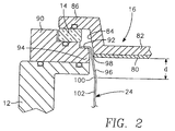
- FIG. 2 illustrates the region around the junction between the target 16 and the chamber wall 12. This figure illustrates neither the rotatable magnetron nor the cooling water bath used for sputtering cobalt.
- a cobalt target layer 80 is solder bonded or otherwise connected to a backing plate 82 composed of, for example, aluminum or copper. Both the target layer 80 and the backing plate 82 are formed with a bevel 84 inclined at about 15° outwardly from the front to the back of the target 14. The bevel angle may be designed to other values between 5° and 45°.
- the target backing plate 82 includes a rim 86 that is vacuum sealed to the ceramic isolator 16 providing electrical isolation between the powered target 16 and the grounded chamber wall 12.
- the isolator 14 is vacuum sealed to an aluminum adapter 90, which in turn is sealed to and electrically connected to the aluminum chamber wall 12.
- the adapter 90 provides flexibility in setting the distance between the target 16 and the wafer 20 and restricts wear to a less expensive and more easily replaced part.
- the shield 24 has an annular outer lip 92 resting on an inner ledge 94 of the adaptor 90 and is electrically connected to the adaptor 90 to be thereby electrically grounded.
- the shield 24 also includes a slanted portion 96 depending from the shield lip 92 and formed at the bevel angle of the target 16 to form a gap 98 between the slanted portion 96 of the shield 24 and the target 16.
- An exemplary thickness of the gap 98 is 80 mils (2mm).
- the gap 98 conveniently assumes a constant thickness when the slanted portion 96 and the target bevel 84 are fabricated with conical shapes.
- the slanted portion 96 extends downwardly and inwardly to a knee 100 below which the shield is formed in a cylindrically shaped straight portion 102.
- the knee 100 is located a distance d below the bottom of the target 16. When there is a gradual transition between the slanted and straight portions 98, 100, the knee is defined as the top of the straight portion 100.
- the straight portion 102 of the shield 24 extends several centimeters below the elevation of the wafer 16 before extending horizontally inwardly in a bowl portion 104 and then upwardly in another cylindrical portion 106, which terminates just below the level of the wafer 18 supported at the process position.
- the outer straight portion 100 acts as the anode for the plasma sputtering process.
- the shield 24 is typically composed of stainless steel, and its interior side may be bead blasted or coated with arc-sprayed aluminum to provide a rougher surface. Sputter deposited material adheres more strongly to a roughened surface, thereby reducing the potential of flaking of material deposited on the shield during the sputtering process.
- the gap 98 between the slanted portion 96 of the shield 24 and the target 16 forms a dark space because the gap 98 is thin enough at all positions adjacent the target 16 at the chamber pressures being used that no plasma is supported in the dark space 98.
- the effect is evident from an inspection of the well known Paschen's curve which shows a minimum of the voltage needed to strike a plasma as a function of the product of pressure and the gap size between electrodes.
- the dark space thus prevents a plasma from forming between the target cathode 16 and the grounded shield 24 in areas where the cathode 16 and shield 24 are separated by only a short distance.
- a plasma can form in areas of larger separations, but this occurs in the plasma processing area and contributes to the sputtering.
- the absence of a plasma in the dark space at the side of the target prevents that area of the target from being sputtered, in particular, the backing plate 82 which has a different composition than the material desired to be sputter deposited.
- the plasma ignition requires that a large number of electrons be emitted from the face of the target and that they ionize the argon gas and start the cascade of excitations resulting in the formation of the argon plasma. If during the ignition process, an excessive number of electrons are transported from the edge of the target to the upper part of the shield 24, their path is relatively short and they do not have an adequate opportunity to interact with the argon gas and ionize it sufficiently into a plasma.
- the electron path during ignition must be made longer on average so as to increase the interaction of the electrons and the argon atoms, which results in plasma ignition. Furthermore, if the dark space at the side of the target is too narrow, the dark current on the target side is much larger, thus draining electrons from the target face.
- the shield knee 100 is located a distance d of about 3mm below the target 16.
- d the distance between the shield knee 100 and the shield portion 102 below the knee 100 quickly becomes relatively far from the target 16.
- the electrons from the target mainly travel to the portion of the shield above the knee 100, and the volume of argon through which the electrons are transported is relatively small. Consequently, the electron loss from the forming plasma is concentrated near the outer periphery of the target 16 and involves too little argon to reliably result in ignition.
- the depth of the shield knee 100 below the target face should be increased above the 3mm of the prior art.
- Two shields have been fabricated for use with a planar target diameter of 329mm at its bottom face between the bevels, a diameter appropriate for sputtering onto a 200mm wafer.
- the first shield has a knee 100 at 9mm below the target 16 and an inner diameter inside of the straight shield portion 102 of 327mm.
- the second shield has a knee at 21mm and an inner diameter of 323mm.
- the shield with the 21mm knee has been tested for ignition with a cobalt target and an argon chamber pressure of 3.85 milliTorr. It produces no ignition delays.
- An ignition delay is defined as more than 3s of the previously described pulsing being required to ignite the plasma. In most cases, the plasma is struck in less than 1s.
- the sputtering shield have a knee located at least 9mm away from the target, more preferably at least 15mm, and most preferably at least 21mm.
- the knee should be located at a radial position with respect to the target center of more than 1mm inside the planar periphery of the target. It is preferred that the knee not be located more than 40mm, more preferably not more than 30mm, from the target and no more than 1cm radially inwardly of the target edge because of diminishing effects and target shadowing. Furthermore, an excessively low knee pinches the plasma too much inwardly and prevents sputtering from the target edge.
- the placement of the shield knee further away from the target face and inwardly of the target edge is also related to the knee placement relative to the magnetron. Since the magnetron creates the magnetic field lines that trap electrons and thus extends the plasma, the low and inward placement of shield knee pushes the plasma inwardly and extends it further from the target. Both effects promote ignition and ion transport to the wafer, but excessive pinching to the point of producing non-uniform target sputtering needs to be avoided.
- the invention has been tested with a cobalt target, it should be equally applicable to sputtering from targets of other ferromagnetic materials, such as nickel or nickel-chromium. It is of course understood, that alloying of the target materials by a few weight percent is not unusual, alloying percentages of less than 5 or 10 wt% being typical. However, even broader ferromagnetic alloy systems may advantageously use the invention. Ferromagnetic materials incorporating rare-earth metals are also being developed for semiconductor wafer fabrication. Such metals are also ferromagnetic. The shield of the invention may also be used with non-ferromagnetic materials, even the common aluminum and copper.
- the shield in the described example was grounded, it may be held at another predetermined DC potential with the same effects. Furthermore, electrically floating shields are sometimes used adjacent to the target.
- the invention thus increases the efficiency of sputtering, particularly reliability of plasma ignition, with on minor changes of a simple chamber part.
Abstract
Description
- The invention relates generally to plasma sputtering reactors. In particular, the invention relates to a chamber shield used to promote sputtering and to protect the side of the chamber.
- Sputtering, alternatively called physical vapor deposition (PVD), is the favored technique for depositing materials, particularly metals and metal-based materials, in the fabrication of semiconductor integrated circuits. Sputtering has a high deposition rate and, in most cases, uses relatively simple and inexpensive fabrication equipment and relatively inexpensive material precursors, targets in the case of PVD. The usual type of sputtering used in commercial applications is DC magnetron sputtering, which is limited to the sputtering of metallic target. Sputtering is widely used for the deposition of aluminum (Al) to form metallization levels in semiconductor integrated circuits. More recently, copper deposition by PVD has been developed. However, sputtering is applicable to a wider range of materials useful in the fabrication of semiconductor integrated circuits. Reactive sputtering is well known in which a target of a metal, such as titanium or tantalum, is sputtered in the presence of a reactive gas in the plasma, most typically nitrogen. Thereby, the sputtered metal atoms react with the reactive gas to deposit a metal compound on the wafer, most particularly, a metal nitride, such as titanium nitride using a titanium target in a nitrogen ambient or tantalum nitride using a tantalum target in a nitrogen ambient.
- Sputtering of yet other metals is also important in the fabrication of semiconductor integrated circuits. In a conventional process to contact a metallization of, for example, aluminum to silicon, a thin layer of titanium, typically of thickness less than 15nm, is deposited over narrow source and drain portions of a silicon substrate which have previously been implanted with p-type or n-type dopants such as boron or phosphorous. The wafer is then annealed, such as by rapid thermal processing (RTP), to cause the titanium and silicon near their interface to diffuse together to form a silicide, in this case titanium silicide. The silicide promotes the adhesion of metallization afterwards deposited over the silicide and also provides a more ohmic contact between the metallization and the semiconducting silicon.
- Titanium-based silicides, usually in the form of TiSi2, however, have some limitations. The temperature required to react titanium with silicon to form the silicide is relatively high, in the range of 600 to 900°C dependent upon the characteristics required. This is a relatively high temperature and may deleteriously cause the implanted dopants to diffuse away from the intended region of the junction. Furthermore, titanium silicide has shown a tendency to increase its resistivity as it is deposited into increasingly narrow source and drain widths. An acceptably low sheet resistance of 4Ω/□ is obtained at a line width of 1 µm, but the sheet resistance increases to about 20Ω/□ at 0.3µm.
- For these reasons, alternative silicides have been considered. Both cobalt and nickel silicides offer much promise. Their siliciding temperatures are lower by 50 to 200°C. They introduce less stress during the siliciding process. Their dependence of resistivity upon line width is negligible. Nickel silicide (NiSi) has some potential advantages in its low resistivity, low stress, and low consumption of silicon during siliciding. However, it has not been favored because it is stable only to about 750°C, versus 900° for TiSi2 and 1000° with CoSi2. For these reasons, cobalt silicide has been more extensively investigated as a replacement for titanium silicide.
- Cobalt can be sputtered in a DC magnetron sputter reactor of the type illustrated schematically in FIG. 1.
- A
conventional PVD reactor 10 is illustrated schematically in cross section in FIG. 1, and the illustration is based upon the Endura PVD Reactor available from Applied Materials, Inc. of Santa Clara, California. Thereactor 10 includes avacuum chamber 12 sealed through aceramic isolator 14 to aPVD target 16 composed of the material, usually a metal, to be sputter deposited on awafer 18 held on aheater pedestal electrode 20 by awafer clamp 22. Alternatively to thewafer clamp 22, an electrostatic chuck may be incorporated into thepedestal 20. The target material may be aluminum, copper, aluminum, titanium, tantalum, alloys of these metals or with alloying elements of up to a few percentages, or other metals amenable to DC sputtering. Ashield 24 held within the chamber protects thechamber wall 12 from the sputtered material and provides the anode grounding plane. A selectable and controllableDC power supply 26 negatively biases thetarget 16 to about -600VDC with respect to theshield 24. Conventionally, thepedestal 20 and hence thewafer 18 are left electrically floating, but it nonetheless develops some DC self-bias to attract positively charged ions from the plasma. - A
first gas source 34 supplies a sputtering working gas, typically argon, to thechamber 12 through amass flow controller 36. The can working gas can be admitted from various positions with thechamber 12 including from the bottom, as illustrated, with one or more inlet pipes supplying gas at the back of the shield. The gas penetrate the bottom of theshield 24 or through agap 42 between thewafer clamp 22 and theshield 24 and thepedestal 20. Avacuum system 44 connected to thechamber 12 through awide pumping port 46 maintains interior of thechamber 12 at a low pressure. Although the base pressure can be held to about 10-7Torr or even lower, the conventional pressure of the argon working gas is typically maintained at between about 1 and 1000mTorr. A computer-basedcontroller 48 controls the reactor including theDC power supply 26 and themass flow controller 36. - When the argon is admitted into the chamber, the DC voltage applied between the
target 16 and theshield 24 ignites the argon into a plasma, and the positively charged argon ions are attracted to the negativelycharged target 16. The ions strike thetarget 16 at a substantial energy and cause target atoms or atomic clusters to be sputtered from thetarget 16. Some of the target particles strike thewafer 18 and are thereby deposited on it, thereby forming a film of the target material. - To provide efficient sputtering, a
magnetron 50 is positioned in back of thetarget 14. It has opposedmagnets magnetic yoke 56 producing a magnetic field within the chamber in the neighborhood of themagnets density plasma region 58 within the chamber adjacent to themagnetron 50. To achieve full coverage in sputtering of thetarget 14, themagnetron 50 is usually rotated about thecenter 60 of thetarget 14 by ashaft 62 driven by an unillustrated motor. - Sputtering of the very thin cobalt layer needed for siliciding does not require a high deposition rate nor, as a result, a significantly high plasma density in the region beneath the magnetron. Therefore, the target power may be set to less than 1kW for a 200mm wafer, compared to 20kW or more for some types of aluminum or copper sputtering. For such thin layers required for siliciding, the layer thickness must be carefully controlled so that excessive silicon is not consumed in the siliciding process. Lower power for sputtering thin cobalt layers improves the thickness control.
- Sputtering of cobalt, though, presents some fundamentally different problems from the sputtering of aluminum, copper, or titanium. Cobalt is a ferromagnetic material. As a result, the magnetic field produced by the magnetron is at least partially shunted through the cobalt target and does not contribute to the formation of the high-density plasma region. Some diminution of the plasma density because of the reduced magnetic flux beneath the magnetron is not a major problem for cobalt sputtering because the cobalt deposition rate need not be all that high. However, ignition of the plasma with a ferromagnetic target does present a problem.
- Plasma ignition can present a significant problem, especially in the geometries representative of a commercially significant plasma reactor. The initial excitation of a plasma requires a high voltage, though with essentially no current, to cause the working gas to be excited into the electrons and positive ions of an electron. This condition must persist for a time period and over a space sufficient to support a low-resistance, essentially neutral plasma between the two electrodes in the case of a capacitively coupled plasma. The maintenance of a plasma requires a feedback condition in which at least as many argon atoms, if argon is the dominant gas, are excited into ions and electrons as are lost. Electron loss to the walls is the usual limiting factor. If too many electrons are lost, the plasma collapses or is never formed.
- It has been observed that plasma ignition with a cobalt plasma is very unreliable. Often ignition requires as much time as would be expended in the actual deposition of cobalt and requires several attempts at the ignition sequence.
- Hence, it is greatly desired that a means be provided for reliably igniting the plasma for sputtering cobalt and other materials, particularly ferromagnetic materials.
- A chamber shield for use in a DC magnetron plasma sputter reactor has a form favoring an extended dark space between the shield and the target. The shield extends downwardly from the target inside of the chamber walls to protect the walls from being coated with sputtered material. The shield is typically grounded with respect to the negatively biased target and thus also acts as an anode for the plasma discharge. The shield includes a slanted portion separated by a small constant gap from beveled edges on the side of the targets. The gap is small enough to act as a dark space preventing a plasma from forming across the dark space. The shield also includes a straight cylindrical portion extending between the target and wafer inside the chamber walls. The slanted portion transitions to the straight portion at a knee. According to the invention, the knee is disposed further away from the target than is normal for aluminum and copper sputtering, preferably more than 9mm and less than 20mm.
- The following is a description of some specific embodiments of the invention, reference being made to the accompanying drawings in which:
- FIG. 1 is a cross-sectional view of a DC magnetron sputter reactor.
- FIG. 2 is a cross-sectional view of an embodiment of a plasma sputtering shield of the invention usable with the sputter reactor of FIG. 1.
-
- The ignition of a plasma even with non-magnetic targets requires some care. The
DC power source 26 illustrated in FIG. 1 is typically a relatively complex electronic power supply system. It must be capable of supplying DC power of relatively high voltages but virtually no current during the ignition phase and then switching to supply DC power of reduced voltages but relatively high current after the plasma has ignited. An ignition voltage of-1500VDC is typical in commercial DC sputter reactors of the illustrated geometry. - Cobalt is usually deposited as part of a barrier or other interfacial layer, and thus its required thickness is relatively small. Therefore, sputtering deposition rates for cobalt are kept relatively low to better control the deposition thickness. Between about 500 to 1000W of DC power is typically used during the deposition stage to sputter deposit cobalt onto 200mm wafers. For wafers of other sizes, the power generally scales with the wafer area although deposition rates also depend upon other chamber characteristics. The power is typically supplied with a voltage of about -450VDC to -480VDC at a current in the vicinity of 2 to 5A. At these sputtering powers, cobalt of the desired thickness can be deposited in about 15s. The switching between these two modes is done partially by a soft output stage of the
DC power supply 26 and partially by active control circuitry, which measures the current being supplied. - Furthermore, for igniting a plasma with a cobalt target, the ignition sequence repetitively pulses the supplied DC voltage between zero and -1500VDC with a pulsing period of between 100 and 200ms. If during any pulse, the current rises above a predetermined level indicating plasma ignition, the ignition sequence is stopped, and the output of the
DC power supply 26 is switched to the deposition mode. - However, with cobalt targets, it has been observed than 4 to 10 seconds of ignition pulsing is often required. Sometimes, even after the lapse of 10 seconds, a plasma has failed to ignite, and a system fault may be declared requiring operator intervention. We believe that ignition is compromised by a concentration of electron loss at the corner of the target just inside of the dark space gap as the electrons are grounded to the shield. As a result, an insufficient volume of argon is ionized, particularly far away from the chamber wall shield.
- The cross-sectional view of FIG. 2 illustrates the region around the junction between the
target 16 and thechamber wall 12. This figure illustrates neither the rotatable magnetron nor the cooling water bath used for sputtering cobalt. Acobalt target layer 80 is solder bonded or otherwise connected to abacking plate 82 composed of, for example, aluminum or copper. Both thetarget layer 80 and thebacking plate 82 are formed with abevel 84 inclined at about 15° outwardly from the front to the back of thetarget 14. The bevel angle may be designed to other values between 5° and 45°. Thetarget backing plate 82 includes arim 86 that is vacuum sealed to theceramic isolator 16 providing electrical isolation between thepowered target 16 and the groundedchamber wall 12. Theisolator 14 is vacuum sealed to analuminum adapter 90, which in turn is sealed to and electrically connected to thealuminum chamber wall 12. Theadapter 90 provides flexibility in setting the distance between thetarget 16 and thewafer 20 and restricts wear to a less expensive and more easily replaced part. - The
shield 24 has an annularouter lip 92 resting on aninner ledge 94 of theadaptor 90 and is electrically connected to theadaptor 90 to be thereby electrically grounded. Theshield 24 also includes a slantedportion 96 depending from theshield lip 92 and formed at the bevel angle of thetarget 16 to form agap 98 between the slantedportion 96 of theshield 24 and thetarget 16. An exemplary thickness of thegap 98 is 80 mils (2mm). Thegap 98 conveniently assumes a constant thickness when the slantedportion 96 and thetarget bevel 84 are fabricated with conical shapes. - The slanted
portion 96 extends downwardly and inwardly to aknee 100 below which the shield is formed in a cylindrically shapedstraight portion 102. Theknee 100 is located a distance d below the bottom of thetarget 16. When there is a gradual transition between the slanted andstraight portions straight portion 100. - As illustrated in FIG. 1, the
straight portion 102 of theshield 24 extends several centimeters below the elevation of thewafer 16 before extending horizontally inwardly in abowl portion 104 and then upwardly in anothercylindrical portion 106, which terminates just below the level of thewafer 18 supported at the process position. The outerstraight portion 100 acts as the anode for the plasma sputtering process. Theshield 24 is typically composed of stainless steel, and its interior side may be bead blasted or coated with arc-sprayed aluminum to provide a rougher surface. Sputter deposited material adheres more strongly to a roughened surface, thereby reducing the potential of flaking of material deposited on the shield during the sputtering process. - The
gap 98 between the slantedportion 96 of theshield 24 and thetarget 16 forms a dark space because thegap 98 is thin enough at all positions adjacent thetarget 16 at the chamber pressures being used that no plasma is supported in thedark space 98. The effect is evident from an inspection of the well known Paschen's curve which shows a minimum of the voltage needed to strike a plasma as a function of the product of pressure and the gap size between electrodes. The dark space thus prevents a plasma from forming between thetarget cathode 16 and the groundedshield 24 in areas where thecathode 16 andshield 24 are separated by only a short distance. A plasma can form in areas of larger separations, but this occurs in the plasma processing area and contributes to the sputtering. The absence of a plasma in the dark space at the side of the target prevents that area of the target from being sputtered, in particular, thebacking plate 82 which has a different composition than the material desired to be sputter deposited. - The plasma ignition requires that a large number of electrons be emitted from the face of the target and that they ionize the argon gas and start the cascade of excitations resulting in the formation of the argon plasma. If during the ignition process, an excessive number of electrons are transported from the edge of the target to the upper part of the
shield 24, their path is relatively short and they do not have an adequate opportunity to interact with the argon gas and ionize it sufficiently into a plasma. The electron path during ignition must be made longer on average so as to increase the interaction of the electrons and the argon atoms, which results in plasma ignition. Furthermore, if the dark space at the side of the target is too narrow, the dark current on the target side is much larger, thus draining electrons from the target face. - The structure as already described above is conventional. For one type of shield used in sputtering aluminum, the
shield knee 100 is located a distance d of about 3mm below thetarget 16. Such a shield has proven unsatisfactory for cobalt sputtering. We believe the problem is that with ahigh shield knee 100 relatively close to thetarget 16, theshield portion 102 below theknee 100 quickly becomes relatively far from thetarget 16. As a result, the electrons from the target mainly travel to the portion of the shield above theknee 100, and the volume of argon through which the electrons are transported is relatively small. Consequently, the electron loss from the forming plasma is concentrated near the outer periphery of thetarget 16 and involves too little argon to reliably result in ignition. We believe reliable ignition is promoted when the electron loss during ignition is spread over a larger target area. When theshield knee 100 is lowered, there is a larger portion of theshield 24 above theknee 100 to which the electrons are attracted and from a larger area of thetarget 80. As a result, there is more argon in the electron path, and the argon is thereby more reliably ignited into a plasma. Although we believe the above explanation explains the behavior we observed, our invention is not limited by the above theory of its operation. - In order to make the ignition more reliable, the depth of the
shield knee 100 below the target face should be increased above the 3mm of the prior art. Two shields have been fabricated for use with a planar target diameter of 329mm at its bottom face between the bevels, a diameter appropriate for sputtering onto a 200mm wafer. The first shield has aknee 100 at 9mm below thetarget 16 and an inner diameter inside of thestraight shield portion 102 of 327mm. The second shield has a knee at 21mm and an inner diameter of 323mm. - The shield with the 21mm knee has been tested for ignition with a cobalt target and an argon chamber pressure of 3.85 milliTorr. It produces no ignition delays. An ignition delay is defined as more than 3s of the previously described pulsing being required to ignite the plasma. In most cases, the plasma is struck in less than 1s. We have observed some ignition delays with the two different shields having 9mm knees. We believe a shield with a 3mm knee will perform worse than that with the 9mm knee. At an intermediate value of, for example, 15mm, satisfactory performance should also be obtained.
- Accordingly, it is preferred that the sputtering shield have a knee located at least 9mm away from the target, more preferably at least 15mm, and most preferably at least 21mm. Alternatively stated, the knee should be located at a radial position with respect to the target center of more than 1mm inside the planar periphery of the target. It is preferred that the knee not be located more than 40mm, more preferably not more than 30mm, from the target and no more than 1cm radially inwardly of the target edge because of diminishing effects and target shadowing. Furthermore, an excessively low knee pinches the plasma too much inwardly and prevents sputtering from the target edge.
- The placement of the shield knee further away from the target face and inwardly of the target edge is also related to the knee placement relative to the magnetron. Since the magnetron creates the magnetic field lines that trap electrons and thus extends the plasma, the low and inward placement of shield knee pushes the plasma inwardly and extends it further from the target. Both effects promote ignition and ion transport to the wafer, but excessive pinching to the point of producing non-uniform target sputtering needs to be avoided.
- Although the invention has been tested with a cobalt target, it should be equally applicable to sputtering from targets of other ferromagnetic materials, such as nickel or nickel-chromium. It is of course understood, that alloying of the target materials by a few weight percent is not unusual, alloying percentages of less than 5 or 10 wt% being typical. However, even broader ferromagnetic alloy systems may advantageously use the invention. Ferromagnetic materials incorporating rare-earth metals are also being developed for semiconductor wafer fabrication. Such metals are also ferromagnetic. The shield of the invention may also be used with non-ferromagnetic materials, even the common aluminum and copper.
- Although the shield in the described example was grounded, it may be held at another predetermined DC potential with the same effects. Furthermore, electrically floating shields are sometimes used adjacent to the target.
- The invention thus increases the efficiency of sputtering, particularly reliability of plasma ignition, with on minor changes of a simple chamber part.
Claims (25)
- A metal shield for use in a sputter reactor including a target having a planar face and a beveled outer periphery, said shield comprising a slanted portion extending along and apart from the beveled outer periphery to form a plasma dark space and a straight portion extending away from said target and in a direction perpendicular to said planar face and jointed to said slanted portion by a knee, wherein said knee is located at least 9mm from said planar face.
- A shield as claimed in claim 1, wherein said target includes a ferromagnetic target portion.
- A shield as claimed in claim 2, wherein said ferromagnetic target portion comprises cobalt.
- A shield as claimed in any of claims 1 to 3, wherein said slanted portion is substantially conically shaped.
- A shield as claimed in any of claims 1 to 4, wherein said knee is located at least 21mm from said planar face.
- A shield as claimed in claim 5, wherein said knee is located no more than 40mm from said planar face.
- A shield as claimed in any of claims 1 to 6, wherein said knee is located more than 1mm radially inwardly of an edge of said target between said planar face and said beveled outer periphery.
- A shield as claimed in any of claims 1 to 7, further comprising:a bottom portion connected to said straight portion behind a substrate being sputter deposited and extending horizontally towards said substrate; anda second straight portion connected to said bottom portion and extending vertically towards said substrate.
- A metal shield for use in a sputter reactor including a target having a planar face and a beveled outer periphery, said shield comprising a slanted portion extending along and apart from the beveled outer periphery to form a plasma dark space and a straight portion extending away from said target and in a direction perpendicular to said planar face and joined to said slanted portion by a knee, wherein said knee is located at least 1mm radially inwardly from an edge of said target between said planar face and said beveled outer periphery.
- A shield as claimed in claim 9, wherein said target includes a ferromagnetic target portion.
- A shield as claimed in claim 10, wherein said ferromagnetic target portion comprises cobalt.
- A shield as claimed in any of claims 9 to 11, wherein said slanted portion is substantially conically shaped.
- A shield as claimed in any of claims 9 to 12, wherein said knee is located no more than 1cm radially inwardly of said edge.
- A shield as claimed in any of claims 9 to 13, wherein said knee is located at least 9mm away a face of said target.
- A shield as claimed in any of claims 9 to 14, further comprising:a bottom portion connected to said straight portion behind a substrate being sputter deposited and extending horizontally towards said substrate; anda second straight portion connected to said bottom portion and extending vertically towards said substrate.
- A sputter reactor, comprising:a vacuum chamber;a support within said chamber for holding on a support surface a substrate to be sputter coated;a target on a side of said chamber in opposition to said support surface comprising a material to be sputter deposited and configured to be connected to a power supply and including a beveled side edge;a metal shield within said chamber held at a predetermined potential and including:a slanted portion extending along and apart from said beveled side edge with a gap therebetween forming a plasma dark space, anda straight portion extending from said target to an elevation in back of said support surface and connected to said slanted portion at a knee,
wherein said knee is located at 9mm away from said target. - A reactor as claimed in claim 16, wherein said knee is located at least 21mm away from said target.
- A reactor as claimed in claim 16 or claim 17, wherein said knee is located no more than 40mm away from said target.
- A reactor as claimed in any of claims 16 to 18, wherein said knee is located more than 1mm radially inside of a corner of said target between a substantially planar face thereof and said beveled said edge.
- A reactor as claimed in claim 19, wherein said knee is located no more than 1cm radially inside of said corner.
- A reactor as claimed in any of claims 16 to 20, wherein said knee is located inwardly of the beveled side edge of said target.
- A reactor as claimed in any of claims 16 to 21, wherein said target comprises a ferromagnetic material.
- A reactor as claimed in claim 22, wherein said ferromagnetic material comprises cobalt.
- A reactor as claimed in claim 22, wherein said ferromagnetic material comprises nickel.
- A reactor as claimed in any of claims 16 to 24, wherein said target is biasable at a negative DC potential and said shield is grounded.
Applications Claiming Priority (2)
| Application Number | Priority Date | Filing Date | Title |
|---|---|---|---|
| US09/425,583 US6149784A (en) | 1999-10-22 | 1999-10-22 | Sputtering chamber shield promoting reliable plasma ignition |
| US425583 | 1999-10-22 |
Publications (1)
| Publication Number | Publication Date |
|---|---|
| EP1094496A2 true EP1094496A2 (en) | 2001-04-25 |
Family
ID=23687174
Family Applications (1)
| Application Number | Title | Priority Date | Filing Date |
|---|---|---|---|
| EP00308668A Withdrawn EP1094496A2 (en) | 1999-10-22 | 2000-10-03 | Sputtering chamber shield promoting reliable plasma ignition |
Country Status (6)
| Country | Link |
|---|---|
| US (1) | US6149784A (en) |
| EP (1) | EP1094496A2 (en) |
| JP (1) | JP4739502B2 (en) |
| KR (1) | KR100677718B1 (en) |
| SG (1) | SG93270A1 (en) |
| TW (1) | TW552310B (en) |
Cited By (10)
| Publication number | Priority date | Publication date | Assignee | Title |
|---|---|---|---|---|
| WO2008133876A2 (en) * | 2007-04-23 | 2008-11-06 | Applied Materials, Inc. | Cooling shield for substrate processing chamber |
| US7670436B2 (en) | 2004-11-03 | 2010-03-02 | Applied Materials, Inc. | Support ring assembly |
| US7762114B2 (en) | 2005-09-09 | 2010-07-27 | Applied Materials, Inc. | Flow-formed chamber component having a textured surface |
| US7910218B2 (en) | 2003-10-22 | 2011-03-22 | Applied Materials, Inc. | Cleaning and refurbishing chamber components having metal coatings |
| US7942969B2 (en) | 2007-05-30 | 2011-05-17 | Applied Materials, Inc. | Substrate cleaning chamber and components |
| US7981262B2 (en) | 2007-01-29 | 2011-07-19 | Applied Materials, Inc. | Process kit for substrate processing chamber |
| US8617672B2 (en) | 2005-07-13 | 2013-12-31 | Applied Materials, Inc. | Localized surface annealing of components for substrate processing chambers |
| US8790499B2 (en) | 2005-11-25 | 2014-07-29 | Applied Materials, Inc. | Process kit components for titanium sputtering chamber |
| US9127362B2 (en) | 2005-10-31 | 2015-09-08 | Applied Materials, Inc. | Process kit and target for substrate processing chamber |
| WO2021034736A1 (en) * | 2019-08-16 | 2021-02-25 | Applied Materials, Inc. | Methods and apparatus for physical vapor deposition (pvd) dielectric deposition |
Families Citing this family (30)
| Publication number | Priority date | Publication date | Assignee | Title |
|---|---|---|---|---|
| KR100412283B1 (en) * | 2001-06-28 | 2003-12-31 | 동부전자 주식회사 | Forming Method For Cobalt Thin Film |
| US6495000B1 (en) | 2001-07-16 | 2002-12-17 | Sharp Laboratories Of America, Inc. | System and method for DC sputtering oxide films with a finned anode |
| KR20030017753A (en) * | 2001-08-22 | 2003-03-04 | 삼성전자주식회사 | Chamber having a double inner sheild ring |
| WO2003021644A1 (en) * | 2001-08-28 | 2003-03-13 | Hyundai Semiconductor America, Inc. | Chamber shields for a plasma chamber |
| US6730174B2 (en) * | 2002-03-06 | 2004-05-04 | Applied Materials, Inc. | Unitary removable shield assembly |
| US6797131B2 (en) * | 2002-11-12 | 2004-09-28 | Applied Materials, Inc. | Design of hardware features to facilitate arc-spray coating applications and functions |
| US20040245098A1 (en) * | 2003-06-04 | 2004-12-09 | Rodger Eckerson | Method of fabricating a shield |
| US20050061857A1 (en) * | 2003-09-24 | 2005-03-24 | Hunt Thomas J. | Method for bonding a sputter target to a backing plate and the assembly thereof |
| US20070158188A1 (en) * | 2004-06-15 | 2007-07-12 | Ivanov Eugene Y | Metal foam shield for sputter reactor |
| US20070158187A1 (en) * | 2006-01-12 | 2007-07-12 | Wagner Andrew V | Cathode for a vacuum sputtering system |
| US7718045B2 (en) * | 2006-06-27 | 2010-05-18 | Applied Materials, Inc. | Ground shield with reentrant feature |
| US8221602B2 (en) * | 2006-12-19 | 2012-07-17 | Applied Materials, Inc. | Non-contact process kit |
| CN101567304B (en) * | 2008-04-23 | 2010-12-01 | 北京北方微电子基地设备工艺研究中心有限责任公司 | Gas distributing device and semiconductor processing device applying same |
| US20100181187A1 (en) * | 2009-01-16 | 2010-07-22 | Applied Materials, Inc. | Charged particle beam pvd device, shielding device, coating chamber for coating substrates, and method of coating |
| CN102356178A (en) * | 2009-01-16 | 2012-02-15 | 应用材料公司 | Charged particle beam pvd device, shielding device, coating chamber for coating substrates, and method of coating |
| US8795487B2 (en) * | 2010-03-31 | 2014-08-05 | Applied Materials, Inc. | Physical vapor deposition chamber with rotating magnet assembly and centrally fed RF power |
| US9834840B2 (en) * | 2010-05-14 | 2017-12-05 | Applied Materials, Inc. | Process kit shield for improved particle reduction |
| US8591709B1 (en) | 2010-05-18 | 2013-11-26 | WD Media, LLC | Sputter deposition shield assembly to reduce cathode shorting |
| US9865440B1 (en) | 2010-11-29 | 2018-01-09 | Seagate Technology Llc | Sputtering shield |
| CN103165375B (en) * | 2011-12-09 | 2016-06-01 | 中国科学院微电子研究所 | Semiconductor chamber preforming device |
| US8702918B2 (en) * | 2011-12-15 | 2014-04-22 | Applied Materials, Inc. | Apparatus for enabling concentricity of plasma dark space |
| US9404174B2 (en) | 2011-12-15 | 2016-08-02 | Applied Materials, Inc. | Pinned target design for RF capacitive coupled plasma |
| US9611539B2 (en) * | 2012-01-27 | 2017-04-04 | Applied Materials, Inc. | Crystalline orientation and overhang control in collision based RF plasmas |
| WO2015023945A1 (en) | 2013-08-16 | 2015-02-19 | Applied Materials, Inc. | Elongated capacitively coupled plasma source for high temperature low pressure environments |
| US9803274B2 (en) * | 2013-11-14 | 2017-10-31 | Taiwan Semiconductor Manufacturing Co., Ltd. | Process kit of physical vapor deposition chamber and fabricating method thereof |
| US9336997B2 (en) | 2014-03-17 | 2016-05-10 | Applied Materials, Inc. | RF multi-feed structure to improve plasma uniformity |
| WO2017091334A1 (en) * | 2015-11-24 | 2017-06-01 | Applied Materials, Inc. | Pre-coated shield for use in vhf-rf pvd chambers |
| US10157733B2 (en) | 2016-01-29 | 2018-12-18 | Applied Materials, Inc. | Methods for igniting a plasma in a substrate processing chamber |
| US11114288B2 (en) * | 2019-02-08 | 2021-09-07 | Applied Materials, Inc. | Physical vapor deposition apparatus |
| US11776793B2 (en) | 2020-11-13 | 2023-10-03 | Applied Materials, Inc. | Plasma source with ceramic electrode plate |
Family Cites Families (3)
| Publication number | Priority date | Publication date | Assignee | Title |
|---|---|---|---|---|
| US5824197A (en) * | 1996-06-05 | 1998-10-20 | Applied Materials, Inc. | Shield for a physical vapor deposition chamber |
| US5736021A (en) * | 1996-07-10 | 1998-04-07 | Applied Materials, Inc. | Electrically floating shield in a plasma reactor |
| EP0846786A3 (en) * | 1996-12-06 | 2001-11-07 | Applied Materials, Inc. | Modified physoical vapor deposition chamber and method of depositing materials at low pressure |
-
1999
- 1999-10-22 US US09/425,583 patent/US6149784A/en not_active Expired - Fee Related
-
2000
- 2000-10-02 SG SG200005625A patent/SG93270A1/en unknown
- 2000-10-02 TW TW089120499A patent/TW552310B/en active
- 2000-10-03 JP JP2000341151A patent/JP4739502B2/en not_active Expired - Fee Related
- 2000-10-03 EP EP00308668A patent/EP1094496A2/en not_active Withdrawn
- 2000-10-04 KR KR1020000058170A patent/KR100677718B1/en not_active IP Right Cessation
Cited By (15)
| Publication number | Priority date | Publication date | Assignee | Title |
|---|---|---|---|---|
| US7910218B2 (en) | 2003-10-22 | 2011-03-22 | Applied Materials, Inc. | Cleaning and refurbishing chamber components having metal coatings |
| US7670436B2 (en) | 2004-11-03 | 2010-03-02 | Applied Materials, Inc. | Support ring assembly |
| US9481608B2 (en) | 2005-07-13 | 2016-11-01 | Applied Materials, Inc. | Surface annealing of components for substrate processing chambers |
| US8617672B2 (en) | 2005-07-13 | 2013-12-31 | Applied Materials, Inc. | Localized surface annealing of components for substrate processing chambers |
| US7762114B2 (en) | 2005-09-09 | 2010-07-27 | Applied Materials, Inc. | Flow-formed chamber component having a textured surface |
| US9127362B2 (en) | 2005-10-31 | 2015-09-08 | Applied Materials, Inc. | Process kit and target for substrate processing chamber |
| US11658016B2 (en) | 2005-10-31 | 2023-05-23 | Applied Materials, Inc. | Shield for a substrate processing chamber |
| US10347475B2 (en) | 2005-10-31 | 2019-07-09 | Applied Materials, Inc. | Holding assembly for substrate processing chamber |
| US8790499B2 (en) | 2005-11-25 | 2014-07-29 | Applied Materials, Inc. | Process kit components for titanium sputtering chamber |
| US7981262B2 (en) | 2007-01-29 | 2011-07-19 | Applied Materials, Inc. | Process kit for substrate processing chamber |
| WO2008133876A2 (en) * | 2007-04-23 | 2008-11-06 | Applied Materials, Inc. | Cooling shield for substrate processing chamber |
| WO2008133876A3 (en) * | 2007-04-23 | 2009-01-29 | Applied Materials Inc | Cooling shield for substrate processing chamber |
| US8980045B2 (en) | 2007-05-30 | 2015-03-17 | Applied Materials, Inc. | Substrate cleaning chamber and components |
| US7942969B2 (en) | 2007-05-30 | 2011-05-17 | Applied Materials, Inc. | Substrate cleaning chamber and components |
| WO2021034736A1 (en) * | 2019-08-16 | 2021-02-25 | Applied Materials, Inc. | Methods and apparatus for physical vapor deposition (pvd) dielectric deposition |
Also Published As
| Publication number | Publication date |
|---|---|
| KR100677718B1 (en) | 2007-02-05 |
| TW552310B (en) | 2003-09-11 |
| JP2001181835A (en) | 2001-07-03 |
| KR20010039989A (en) | 2001-05-15 |
| US6149784A (en) | 2000-11-21 |
| JP4739502B2 (en) | 2011-08-03 |
| SG93270A1 (en) | 2002-12-17 |
Similar Documents
| Publication | Publication Date | Title |
|---|---|---|
| US6149784A (en) | Sputtering chamber shield promoting reliable plasma ignition | |
| US6358376B1 (en) | Biased shield in a magnetron sputter reactor | |
| US5897752A (en) | Wafer bias ring in a sustained self-sputtering reactor | |
| US6620296B2 (en) | Target sidewall design to reduce particle generation during magnetron sputtering | |
| US7294574B2 (en) | Sputter deposition and etching of metallization seed layer for overhang and sidewall improvement | |
| KR100843514B1 (en) | Self-ionized plasma for sputtering copper | |
| US6692617B1 (en) | Sustained self-sputtering reactor having an increased density plasma | |
| US6627050B2 (en) | Method and apparatus for depositing a tantalum-containing layer on a substrate | |
| US6352629B1 (en) | Coaxial electromagnet in a magnetron sputtering reactor | |
| US20080083610A1 (en) | Sputtering Chamber Having Auxiliary Backside Magnet to Improve Etch Uniformity and Magnetron Producing Sustained Self Sputtering of Ruthenium and Tantalum | |
| JP2002538309A (en) | Method and apparatus for ionized physical vapor deposition | |
| WO2009071667A1 (en) | Reactive sputtering with hipims | |
| WO2004061152A1 (en) | Pulsed magnetron target for sputter deposition | |
| WO2003008659A2 (en) | Collimated sputtering of cobalt | |
| US20030211758A1 (en) | Alignment mark shielding ring without arcing defect and method for using | |
| GB2191787A (en) | Process and arrangement for sputtering a material by means of high frequency | |
| JP3798316B2 (en) | Sputtering method using virtual shutter | |
| EP1101834A2 (en) | Method of depositing materials on substrates | |
| US20050233551A1 (en) | Method for depositing silicon by pulsed cathodic vacuum arc | |
| Fu et al. | Deposition of copper by using self-sputtering | |
| EP1076110A1 (en) | Cooling gas used with a self-sputtering method | |
| CN112210763B (en) | Method for depositing a metal layer on a wafer | |
| JP2002294441A (en) | Bias sputtering apparatus | |
| JPH0610345B2 (en) | Sputtering equipment | |
| JP5693175B2 (en) | Sputtering method |
Legal Events
| Date | Code | Title | Description |
|---|---|---|---|
| PUAI | Public reference made under article 153(3) epc to a published international application that has entered the european phase |
Free format text: ORIGINAL CODE: 0009012 |
|
| AK | Designated contracting states |
Kind code of ref document: A2 Designated state(s): AT BE CH CY DE DK ES FI FR GB GR IE IT LI LU MC NL PT SE |
|
| AX | Request for extension of the european patent |
Free format text: AL;LT;LV;MK;RO;SI |
|
| RIN1 | Information on inventor provided before grant (corrected) |
Inventor name: YANG, LISA L. Inventor name: FORSTER, JOHN C. Inventor name: YEE, NELSON A. Inventor name: SU, JINGANG Inventor name: NGAN, KENNY KING-TAI |
|
| STAA | Information on the status of an ep patent application or granted ep patent |
Free format text: STATUS: THE APPLICATION IS DEEMED TO BE WITHDRAWN |
|
| 18D | Application deemed to be withdrawn |
Effective date: 20040504 |