EP1094453A2 - Optical pickup assembly - Google Patents
Optical pickup assembly Download PDFInfo
- Publication number
- EP1094453A2 EP1094453A2 EP00308957A EP00308957A EP1094453A2 EP 1094453 A2 EP1094453 A2 EP 1094453A2 EP 00308957 A EP00308957 A EP 00308957A EP 00308957 A EP00308957 A EP 00308957A EP 1094453 A2 EP1094453 A2 EP 1094453A2
- Authority
- EP
- European Patent Office
- Prior art keywords
- bobbin
- objective lens
- tilt
- tilt coils
- driving
- Prior art date
- Legal status (The legal status is an assumption and is not a legal conclusion. Google has not performed a legal analysis and makes no representation as to the accuracy of the status listed.)
- Granted
Links
Images



Classifications
-
- G—PHYSICS
- G11—INFORMATION STORAGE
- G11B—INFORMATION STORAGE BASED ON RELATIVE MOVEMENT BETWEEN RECORD CARRIER AND TRANSDUCER
- G11B7/00—Recording or reproducing by optical means, e.g. recording using a thermal beam of optical radiation by modifying optical properties or the physical structure, reproducing using an optical beam at lower power by sensing optical properties; Record carriers therefor
- G11B7/08—Disposition or mounting of heads or light sources relatively to record carriers
-
- G—PHYSICS
- G11—INFORMATION STORAGE
- G11B—INFORMATION STORAGE BASED ON RELATIVE MOVEMENT BETWEEN RECORD CARRIER AND TRANSDUCER
- G11B7/00—Recording or reproducing by optical means, e.g. recording using a thermal beam of optical radiation by modifying optical properties or the physical structure, reproducing using an optical beam at lower power by sensing optical properties; Record carriers therefor
- G11B7/08—Disposition or mounting of heads or light sources relatively to record carriers
- G11B7/09—Disposition or mounting of heads or light sources relatively to record carriers with provision for moving the light beam or focus plane for the purpose of maintaining alignment of the light beam relative to the record carrier during transducing operation, e.g. to compensate for surface irregularities of the latter or for track following
- G11B7/0925—Electromechanical actuators for lens positioning
- G11B7/0935—Details of the moving parts
-
- G—PHYSICS
- G11—INFORMATION STORAGE
- G11B—INFORMATION STORAGE BASED ON RELATIVE MOVEMENT BETWEEN RECORD CARRIER AND TRANSDUCER
- G11B7/00—Recording or reproducing by optical means, e.g. recording using a thermal beam of optical radiation by modifying optical properties or the physical structure, reproducing using an optical beam at lower power by sensing optical properties; Record carriers therefor
- G11B7/08—Disposition or mounting of heads or light sources relatively to record carriers
- G11B7/09—Disposition or mounting of heads or light sources relatively to record carriers with provision for moving the light beam or focus plane for the purpose of maintaining alignment of the light beam relative to the record carrier during transducing operation, e.g. to compensate for surface irregularities of the latter or for track following
- G11B7/0925—Electromechanical actuators for lens positioning
- G11B7/0933—Details of stationary parts
-
- G—PHYSICS
- G11—INFORMATION STORAGE
- G11B—INFORMATION STORAGE BASED ON RELATIVE MOVEMENT BETWEEN RECORD CARRIER AND TRANSDUCER
- G11B7/00—Recording or reproducing by optical means, e.g. recording using a thermal beam of optical radiation by modifying optical properties or the physical structure, reproducing using an optical beam at lower power by sensing optical properties; Record carriers therefor
- G11B7/08—Disposition or mounting of heads or light sources relatively to record carriers
- G11B7/09—Disposition or mounting of heads or light sources relatively to record carriers with provision for moving the light beam or focus plane for the purpose of maintaining alignment of the light beam relative to the record carrier during transducing operation, e.g. to compensate for surface irregularities of the latter or for track following
- G11B7/095—Disposition or mounting of heads or light sources relatively to record carriers with provision for moving the light beam or focus plane for the purpose of maintaining alignment of the light beam relative to the record carrier during transducing operation, e.g. to compensate for surface irregularities of the latter or for track following specially adapted for discs, e.g. for compensation of eccentricity or wobble
- G11B7/0956—Disposition or mounting of heads or light sources relatively to record carriers with provision for moving the light beam or focus plane for the purpose of maintaining alignment of the light beam relative to the record carrier during transducing operation, e.g. to compensate for surface irregularities of the latter or for track following specially adapted for discs, e.g. for compensation of eccentricity or wobble to compensate for tilt, skew, warp or inclination of the disc, i.e. maintain the optical axis at right angles to the disc
Definitions
- the present invention relates to an optical pickup assembly, and more particularly, to an optical pickup assembly having an improved structure for tilt control of an objective lens.
- a disk player such as a CDP (compact disk player) or a DVDP (digital versatile disk player) which records information on or or reproduces information from a disk
- the optical pickup assembly is usually provided with a controlling means for driving a bobbin at which an optical system including an objective lens is mounted in a focusing direction and a tracking direction, to perform focusing and tracking control so that light passing through the objective lens can be focused at a precise position on the disk.
- a controlling means for driving a bobbin at which an optical system including an objective lens is mounted in a focusing direction and a tracking direction, to perform focusing and tracking control so that light passing through the objective lens can be focused at a precise position on the disk.
- an optical pickup assembly which can perform tilt control, in addition to focusing and tracking control is required. With tilt control, when a disk is inclined, the optical pickup assembly itself can be tilted corresponding to the inclination of the disk so that light is incident on the disk parallel to the normal.
- Figure 1 shows an optical pickup assembly having a conventional tilt control mechanism.
- an optical pickup assembly including an objective lens 11 is installed as a whole at a pivot shaft 21 of a base 20 to be capable of pivoting.
- a degree of inclination of a disk 1 is measured by sensors 12 and 13 and then a tilt motor 30 is driven to tilt the entire optical pickup assembly 10 by a corresponding angle.
- Reference numeral 40 denotes a feeding motor for reciprocating the base 20 across the disk 1.
- the tilt control mechanism having the above structure since the optical pickup assembly 10 is installed to pivot as a whole, and the tilt motor 30 is additionally installed outside the optical pickup assembly 10, the overall system is large and complicated, which is contrary to the current trend of making systems light and small. Thus, an optical pickup assembly having a light and small structure with which tilt control can be stably performed is required.
- an optical pickup assembly comprises a bobbin at which an objective lens is mounted, an elastic support member for supporting the bobbin to be capable of elastically moving with respect to a holder installed at a base, a focus coil and a tracking coil installed at the bobbin and forming a conducting path for driving the objective lens in a focusing direction and a tracking direction, tilt coils installed at one side of the bobbin and forming a conductive path for driving tilt of the objective lens, a first magnet and a first yoke for generating an electromagnetic force for driving the objective lens together with the current carrying focus coil and tracking coil, a second magnet and a second yoke for generating an electromagnetic force for driving the objective lens together with the current carrying tilt coils, a position detecting sensor for measuring relative inclination of the objective lens with respect to a disk, and a balance member coupled to the bobbin to balance the weight of the tilt coils by applying weight corresponding to the weight of the tilt coils at positions symmetrically opposite
- the balance member comprises: a base panel disposed under the bottom surface of the bobbin; and side panels perpendicularly extending from the base panel and disposed at the sides of the bobbin symmetrically opposite to the tilt coils.
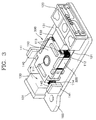
- a holder 120 is fixedly installed on a base 100, and a bobbin 110 at which an objective lens 111 is mounted is elastically and movably supported at the holder 120 by an elastic support member 121.
- a focus coil 112 and tracking coils 113 for aligning the objective lens 111 in a focusing direction and a tracking direction are installed at the bobbin 110.
- a first magnet 130 and a first yoke 131 for magnetic interaction with the current carrying the focus and tracking coils 112 and 113 are installed at the base 100.
- Tilt coils 114 for tilt driving the objective lens 111 in a direction indicated by an arrow of Figure 3 are installed at two adjacent corners of the bobbin 110.
- Pivoting in the direction indicated by the arrow is performed due to interaction between the current carrying the tilt coils 114 and the second magnets 140 and yokes 141 installed on the base 100.
- the second magnets 140 are formed in pairs and magnetized in the opposite directions to one another, as shown in Figure 4, and installed at the upper and lower portions of each of the yokes 141 to face the upper and lower portions of each of the tilt coils 114.
- Reference numeral 200 denotes a cover member for covering members including the bobbin 110 and the holder 120 installed on the base 100.
- First and second position detecting sensors 201 and 202 for measuring relative inclination between the objective lens 111 and a disk (not shown) are installed on the cover member 200.
- the first position detecting sensor 201 is installed on the upper and outer surface of the cover member 200 to measure inclination of the disk with respect to the cover member 200.
- the second position detecting sensor 202 is installed on the side and inner surface of the cover member 200 to measure inclination of the objective lens 111 with respect to the cover member 200. Thus, values measured by the sensors 201 and 202 are compared with each other to calculate relative inclination between the disk and the objective lens 111. Then, current is applied to the tilt coils 114 to perform tilt control.
- a balance member 300 for balancing the weight of the tilt coils 114 is installed under the bobbin 110.
- the balance member 300 consists of a base panel 310 disposed under the bottom of the bobbin 110 and side panels 320 disposed at the sides of the bobbin 110.
- the side panels 320 apply weight corresponding to the weight of the tilt coils 114 at the positions symmetrical to the positions of the tilt coils 114.
- the weight of the tilt coils 114 is balanced by the weight of the side panels 320 of the balance member 300 so that the bobbin 110 can be maintained in a balanced state.
- the reason for installing the balance member 300 is that, when the bobbin 110 loses its balance and is inclined in one direction due to the weight of the tilt coils 114, since the load on all control mechanism including focus control, tracking control and tilt control increases. Thus, when the balance member 300 is installed, the balance of the bobbin 110 is maintained so that the above controls can be stably performed.
- the side panel 320 of the balance member 300 can also be used as a reflection plate for measuring inclination of the second position detecting sensor 202.
- the assembly can be manufactured to be slim and light. Also, by installing the balance member to balance the weight distribution of the bobbin, control can be stably performed.
Landscapes
- Optical Recording Or Reproduction (AREA)
Abstract
Description
Claims (2)
- An optical pickup assembly including a bobbin (110) at which an objective lens (111) is mounted, an elastic support member (121) for supporting the bobbin (110) to be capable of elastically moving with respect to a holder (120) installed at a base (100), a focus coil (112) and a tracking coil (113) installed at the bobbin (110) and forming a conducting path for driving the objective lens (111) in a focusing direction and a tracking direction, and a first magnet (130) and a first yoke (131) for generating an electromagnetic force for driving the objective lens (111) together with the current carrying focus coil (112) and tracking coil (113), characterized by comprising tilt coils (114) installed at one side of the bobbin (110) and forming a conductive path for driving tilt of the objective lens (111), a second magnet (140) and a second yoke (141) for generating an electromagnetic force for driving the objective lens (111) together with the current carrying tilt coils (114), a position detecting sensor (201, 202) for measuring relative inclination of the objective lens (111) with respect to a disk, and a balance member (300) coupled to the bobbin (110) to balance the weight of the tilt coils by applying weight corresponding to the weight of the tilt coils (114) at positions symmetrically opposite to the positions of the tilt coils (114).
- The assembly as claimed in claim 1, wherein the balance member (300) comprises:a base panel (310) disposed under the bottom surface of the bobbin (110); andside panels (320) perpendicularly extending from the base panel (310) and disposed at the sides of the bobbin (110) symmetrically opposite to the tilt coils (114).
Applications Claiming Priority (2)
| Application Number | Priority Date | Filing Date | Title |
|---|---|---|---|
| KR1019990045847A KR100636103B1 (en) | 1999-10-21 | 1999-10-21 | Optical pickup assembly |
| KR9945847 | 1999-10-21 |
Publications (3)
| Publication Number | Publication Date |
|---|---|
| EP1094453A2 true EP1094453A2 (en) | 2001-04-25 |
| EP1094453A3 EP1094453A3 (en) | 2004-01-14 |
| EP1094453B1 EP1094453B1 (en) | 2006-03-15 |
Family
ID=36217516
Family Applications (1)
| Application Number | Title | Priority Date | Filing Date |
|---|---|---|---|
| EP00308957A Expired - Lifetime EP1094453B1 (en) | 1999-10-21 | 2000-10-11 | Optical pickup assembly |
Country Status (6)
| Country | Link |
|---|---|
| US (1) | US6466529B1 (en) |
| EP (1) | EP1094453B1 (en) |
| JP (1) | JP2001134969A (en) |
| KR (1) | KR100636103B1 (en) |
| CN (1) | CN1144192C (en) |
| DE (1) | DE60026672T2 (en) |
Cited By (1)
| Publication number | Priority date | Publication date | Assignee | Title |
|---|---|---|---|---|
| EP1675111A3 (en) * | 2004-12-22 | 2006-10-04 | Samsung Electronics Co., Ltd. | Optical pickup actuator and optical recording-reproducing apparatus |
Families Citing this family (19)
| Publication number | Priority date | Publication date | Assignee | Title |
|---|---|---|---|---|
| KR100580243B1 (en) * | 1999-10-21 | 2006-05-16 | 삼성전자주식회사 | Optical pickup assembly |
| KR100438276B1 (en) * | 2001-02-14 | 2004-07-02 | 엘지전자 주식회사 | Optical pick-up actuator for radial tilting drive |
| KR100436720B1 (en) * | 2001-08-28 | 2004-06-22 | 삼성전기주식회사 | Optical pick-up actuator |
| KR100436721B1 (en) * | 2001-08-31 | 2004-06-22 | 삼성전기주식회사 | Drive device of objective lens |
| JP2003123288A (en) * | 2001-10-12 | 2003-04-25 | Funai Electric Co Ltd | Device for supporting objective lens |
| JP2003242671A (en) * | 2002-02-15 | 2003-08-29 | Sanyo Electric Co Ltd | Device for installing suspension for actuator |
| KR20030093683A (en) * | 2002-06-05 | 2003-12-11 | 삼성전자주식회사 | Compatible optical pickup |
| US7272840B2 (en) * | 2002-08-24 | 2007-09-18 | Samsung Electronics Co., Ltd. | Objective lens driving apparatus used with an optical pickup |
| TW200405314A (en) * | 2002-08-24 | 2004-04-01 | Samsung Electronics Co Ltd | Objective lens driving apparatus for optical pickup |
| JP2004295932A (en) * | 2003-03-25 | 2004-10-21 | Funai Electric Co Ltd | Objective lens driving device for optical head |
| US7079329B2 (en) * | 2003-06-17 | 2006-07-18 | Lg Electronics Inc. | Micro actuator for controlling focal depth |
| JP2005018863A (en) * | 2003-06-25 | 2005-01-20 | Sankyo Seiki Mfg Co Ltd | Optical pickup device |
| JP3855977B2 (en) * | 2003-07-16 | 2006-12-13 | ソニー株式会社 | Optical pickup and disk drive device |
| KR100510538B1 (en) * | 2003-08-04 | 2005-08-26 | 삼성전자주식회사 | Optical pickup actuator |
| JP2006066048A (en) * | 2003-12-25 | 2006-03-09 | Nidec Sankyo Corp | Objective lens drive device and optical head device provided therewith |
| JP2006004484A (en) * | 2004-06-16 | 2006-01-05 | Hitachi Media Electoronics Co Ltd | Objective lens driving device and optical disk device |
| KR20060074443A (en) * | 2004-12-27 | 2006-07-03 | 엘지전자 주식회사 | Optical pickup actuator |
| US10320678B2 (en) * | 2014-03-21 | 2019-06-11 | Avago Technologies International Sales Pte. Limited | Mapping control protocol time onto a physical layer |
| TWI650587B (en) * | 2016-08-04 | 2019-02-11 | 台灣東電化股份有限公司 | Lens drive |
Family Cites Families (7)
| Publication number | Priority date | Publication date | Assignee | Title |
|---|---|---|---|---|
| US5430699A (en) * | 1993-02-24 | 1995-07-04 | Matsushita Electric Industrial Co., Ltd. | Optical reading and writing device |
| JP3323699B2 (en) * | 1995-07-05 | 2002-09-09 | 松下電器産業株式会社 | Objective lens drive |
| JPH09282693A (en) * | 1996-04-15 | 1997-10-31 | Nec Corp | Optical head device |
| JPH10261233A (en) * | 1997-01-14 | 1998-09-29 | Matsushita Electric Ind Co Ltd | Objective lens drive |
| US5905255A (en) * | 1997-01-14 | 1999-05-18 | Matsushita Electric Industrial Co., Ltd. | Objective lens driver |
| SG72954A1 (en) * | 1998-05-21 | 2000-05-23 | Samsung Electronics Co Ltd | Optical pickup |
| US6341104B1 (en) * | 1998-08-03 | 2002-01-22 | Matsushita Electric Industrial Co., Ltd. | Optical pickup apparatus of tilt control type |
-
1999
- 1999-10-21 KR KR1019990045847A patent/KR100636103B1/en not_active Expired - Fee Related
-
2000
- 2000-10-06 US US09/680,463 patent/US6466529B1/en not_active Expired - Fee Related
- 2000-10-10 JP JP2000309766A patent/JP2001134969A/en active Pending
- 2000-10-11 EP EP00308957A patent/EP1094453B1/en not_active Expired - Lifetime
- 2000-10-11 DE DE60026672T patent/DE60026672T2/en not_active Expired - Lifetime
- 2000-10-16 CN CNB001314475A patent/CN1144192C/en not_active Expired - Fee Related
Cited By (2)
| Publication number | Priority date | Publication date | Assignee | Title |
|---|---|---|---|---|
| EP1675111A3 (en) * | 2004-12-22 | 2006-10-04 | Samsung Electronics Co., Ltd. | Optical pickup actuator and optical recording-reproducing apparatus |
| US7668049B2 (en) | 2004-12-22 | 2010-02-23 | Samsung Electronics Co., Ltd. | Optical pickup actuator and optical recording/reproducing apparatus |
Also Published As
| Publication number | Publication date |
|---|---|
| DE60026672T2 (en) | 2006-09-07 |
| EP1094453B1 (en) | 2006-03-15 |
| KR20010038041A (en) | 2001-05-15 |
| DE60026672D1 (en) | 2006-05-11 |
| CN1144192C (en) | 2004-03-31 |
| KR100636103B1 (en) | 2006-10-18 |
| EP1094453A3 (en) | 2004-01-14 |
| CN1294381A (en) | 2001-05-09 |
| JP2001134969A (en) | 2001-05-18 |
| US6466529B1 (en) | 2002-10-15 |
Similar Documents
| Publication | Publication Date | Title |
|---|---|---|
| EP1094453A2 (en) | Optical pickup assembly | |
| US6449229B1 (en) | Optical pickup assembly with adjustable inclination | |
| US6295255B1 (en) | Optical pickup having a tilt mechanism to adjust an optical axis of an incident light beam | |
| KR100297771B1 (en) | Actuator for optical pickup | |
| EP1394784B1 (en) | Objective lens driving apparatus used with an optical pickup | |
| KR100970723B1 (en) | Objective lens driving device for optical pickup | |
| US7272840B2 (en) | Objective lens driving apparatus used with an optical pickup | |
| US7349295B2 (en) | Optical head device | |
| JP2851812B2 (en) | Lens drive | |
| EP1342236B1 (en) | Optical scanning device comprising a tiltable lens system | |
| JP2001110076A (en) | Optical pickup device | |
| JP3801517B2 (en) | Optical pickup | |
| KR100319857B1 (en) | Optical pickup device | |
| JPH05205283A (en) | Objective lens driver for optical pickup | |
| KR100518872B1 (en) | Optical pick-up system | |
| JP3371384B2 (en) | Two-axis actuator | |
| JPS6013332A (en) | Supporting device of optical system | |
| US7701812B2 (en) | Optical element driving apparatus | |
| KR20010038068A (en) | Optical pickup assembly | |
| JP2611058B2 (en) | Objective lens drive | |
| KR100220510B1 (en) | Super thin type optical pick up actuator | |
| US8171506B2 (en) | Optical-system driving device effecting switchover between objective lenses for achieving focal spots | |
| KR0177331B1 (en) | Optical pickup actuator for both CD and DVD | |
| JPH08203102A (en) | Objective lens drive | |
| JP2005337907A (en) | Optical sensor and actuator using it |
Legal Events
| Date | Code | Title | Description |
|---|---|---|---|
| PUAI | Public reference made under article 153(3) epc to a published international application that has entered the european phase |
Free format text: ORIGINAL CODE: 0009012 |
|
| 17P | Request for examination filed |
Effective date: 20001023 |
|
| AK | Designated contracting states |
Kind code of ref document: A2 Designated state(s): AT BE CH CY DE DK ES FI FR GB GR IE IT LI LU MC NL PT SE |
|
| AX | Request for extension of the european patent |
Free format text: AL;LT;LV;MK;RO;SI |
|
| PUAL | Search report despatched |
Free format text: ORIGINAL CODE: 0009013 |
|
| AK | Designated contracting states |
Kind code of ref document: A3 Designated state(s): AT BE CH CY DE DK ES FI FR GB GR IE IT LI LU MC NL PT SE |
|
| AX | Request for extension of the european patent |
Extension state: AL LT LV MK RO SI |
|
| RIC1 | Information provided on ipc code assigned before grant |
Ipc: 7G 11B 7/095 B Ipc: 7G 11B 7/09 A |
|
| 17Q | First examination report despatched |
Effective date: 20040429 |
|
| AKX | Designation fees paid |
Designated state(s): DE FR GB NL |
|
| GRAP | Despatch of communication of intention to grant a patent |
Free format text: ORIGINAL CODE: EPIDOSNIGR1 |
|
| GRAS | Grant fee paid |
Free format text: ORIGINAL CODE: EPIDOSNIGR3 |
|
| GRAA | (expected) grant |
Free format text: ORIGINAL CODE: 0009210 |
|
| AK | Designated contracting states |
Kind code of ref document: B1 Designated state(s): DE FR GB NL |
|
| REG | Reference to a national code |
Ref country code: GB Ref legal event code: FG4D |
|
| REF | Corresponds to: |
Ref document number: 60026672 Country of ref document: DE Date of ref document: 20060511 Kind code of ref document: P |
|
| ET | Fr: translation filed | ||
| PLBE | No opposition filed within time limit |
Free format text: ORIGINAL CODE: 0009261 |
|
| STAA | Information on the status of an ep patent application or granted ep patent |
Free format text: STATUS: NO OPPOSITION FILED WITHIN TIME LIMIT |
|
| 26N | No opposition filed |
Effective date: 20061218 |
|
| PGFP | Annual fee paid to national office [announced via postgrant information from national office to epo] |
Ref country code: GB Payment date: 20120920 Year of fee payment: 13 |
|
| PGFP | Annual fee paid to national office [announced via postgrant information from national office to epo] |
Ref country code: FR Payment date: 20120927 Year of fee payment: 13 |
|
| PGFP | Annual fee paid to national office [announced via postgrant information from national office to epo] |
Ref country code: NL Payment date: 20120920 Year of fee payment: 13 Ref country code: DE Payment date: 20120920 Year of fee payment: 13 |
|
| REG | Reference to a national code |
Ref country code: NL Ref legal event code: V1 Effective date: 20140501 |
|
| GBPC | Gb: european patent ceased through non-payment of renewal fee |
Effective date: 20131011 |
|
| PG25 | Lapsed in a contracting state [announced via postgrant information from national office to epo] |
Ref country code: GB Free format text: LAPSE BECAUSE OF NON-PAYMENT OF DUE FEES Effective date: 20131011 |
|
| REG | Reference to a national code |
Ref country code: FR Ref legal event code: ST Effective date: 20140630 |
|
| REG | Reference to a national code |
Ref country code: DE Ref legal event code: R119 Ref document number: 60026672 Country of ref document: DE Effective date: 20140501 |
|
| PG25 | Lapsed in a contracting state [announced via postgrant information from national office to epo] |
Ref country code: FR Free format text: LAPSE BECAUSE OF NON-PAYMENT OF DUE FEES Effective date: 20131031 Ref country code: NL Free format text: LAPSE BECAUSE OF NON-PAYMENT OF DUE FEES Effective date: 20140501 Ref country code: DE Free format text: LAPSE BECAUSE OF NON-PAYMENT OF DUE FEES Effective date: 20140501 |