EP1094286A1 - Verfahren und Vorrichtung zur Tieftemperaturzerlegung von Luft - Google Patents
Verfahren und Vorrichtung zur Tieftemperaturzerlegung von Luft Download PDFInfo
- Publication number
- EP1094286A1 EP1094286A1 EP00119941A EP00119941A EP1094286A1 EP 1094286 A1 EP1094286 A1 EP 1094286A1 EP 00119941 A EP00119941 A EP 00119941A EP 00119941 A EP00119941 A EP 00119941A EP 1094286 A1 EP1094286 A1 EP 1094286A1
- Authority
- EP
- European Patent Office
- Prior art keywords
- pressure column
- section
- condenser
- evaporator
- low
- Prior art date
- Legal status (The legal status is an assumption and is not a legal conclusion. Google has not performed a legal analysis and makes no representation as to the accuracy of the status listed.)
- Granted
Links
Images

Classifications
-
- F—MECHANICAL ENGINEERING; LIGHTING; HEATING; WEAPONS; BLASTING
- F25—REFRIGERATION OR COOLING; COMBINED HEATING AND REFRIGERATION SYSTEMS; HEAT PUMP SYSTEMS; MANUFACTURE OR STORAGE OF ICE; LIQUEFACTION SOLIDIFICATION OF GASES
- F25J—LIQUEFACTION, SOLIDIFICATION OR SEPARATION OF GASES OR GASEOUS OR LIQUEFIED GASEOUS MIXTURES BY PRESSURE AND COLD TREATMENT OR BY BRINGING THEM INTO THE SUPERCRITICAL STATE
- F25J3/00—Processes or apparatus for separating the constituents of gaseous or liquefied gaseous mixtures involving the use of liquefaction or solidification
- F25J3/02—Processes or apparatus for separating the constituents of gaseous or liquefied gaseous mixtures involving the use of liquefaction or solidification by rectification, i.e. by continuous interchange of heat and material between a vapour stream and a liquid stream
- F25J3/04—Processes or apparatus for separating the constituents of gaseous or liquefied gaseous mixtures involving the use of liquefaction or solidification by rectification, i.e. by continuous interchange of heat and material between a vapour stream and a liquid stream for air
- F25J3/04763—Start-up or control of the process; Details of the apparatus used
- F25J3/04866—Construction and layout of air fractionation equipments, e.g. valves, machines
- F25J3/04872—Vertical layout of cold equipments within in the cold box, e.g. columns, heat exchangers etc.
- F25J3/04878—Side by side arrangement of multiple vessels in a main column system, wherein the vessels are normally mounted one upon the other or forming different sections of the same column
-
- F—MECHANICAL ENGINEERING; LIGHTING; HEATING; WEAPONS; BLASTING
- F25—REFRIGERATION OR COOLING; COMBINED HEATING AND REFRIGERATION SYSTEMS; HEAT PUMP SYSTEMS; MANUFACTURE OR STORAGE OF ICE; LIQUEFACTION SOLIDIFICATION OF GASES
- F25J—LIQUEFACTION, SOLIDIFICATION OR SEPARATION OF GASES OR GASEOUS OR LIQUEFIED GASEOUS MIXTURES BY PRESSURE AND COLD TREATMENT OR BY BRINGING THEM INTO THE SUPERCRITICAL STATE
- F25J3/00—Processes or apparatus for separating the constituents of gaseous or liquefied gaseous mixtures involving the use of liquefaction or solidification
- F25J3/02—Processes or apparatus for separating the constituents of gaseous or liquefied gaseous mixtures involving the use of liquefaction or solidification by rectification, i.e. by continuous interchange of heat and material between a vapour stream and a liquid stream
- F25J3/04—Processes or apparatus for separating the constituents of gaseous or liquefied gaseous mixtures involving the use of liquefaction or solidification by rectification, i.e. by continuous interchange of heat and material between a vapour stream and a liquid stream for air
- F25J3/04006—Providing pressurised feed air or process streams within or from the air fractionation unit
- F25J3/04078—Providing pressurised feed air or process streams within or from the air fractionation unit providing pressurized products by liquid compression and vaporisation with cold recovery, i.e. so-called internal compression
- F25J3/0409—Providing pressurised feed air or process streams within or from the air fractionation unit providing pressurized products by liquid compression and vaporisation with cold recovery, i.e. so-called internal compression of oxygen
-
- F—MECHANICAL ENGINEERING; LIGHTING; HEATING; WEAPONS; BLASTING
- F25—REFRIGERATION OR COOLING; COMBINED HEATING AND REFRIGERATION SYSTEMS; HEAT PUMP SYSTEMS; MANUFACTURE OR STORAGE OF ICE; LIQUEFACTION SOLIDIFICATION OF GASES
- F25J—LIQUEFACTION, SOLIDIFICATION OR SEPARATION OF GASES OR GASEOUS OR LIQUEFIED GASEOUS MIXTURES BY PRESSURE AND COLD TREATMENT OR BY BRINGING THEM INTO THE SUPERCRITICAL STATE
- F25J3/00—Processes or apparatus for separating the constituents of gaseous or liquefied gaseous mixtures involving the use of liquefaction or solidification
- F25J3/02—Processes or apparatus for separating the constituents of gaseous or liquefied gaseous mixtures involving the use of liquefaction or solidification by rectification, i.e. by continuous interchange of heat and material between a vapour stream and a liquid stream
- F25J3/04—Processes or apparatus for separating the constituents of gaseous or liquefied gaseous mixtures involving the use of liquefaction or solidification by rectification, i.e. by continuous interchange of heat and material between a vapour stream and a liquid stream for air
- F25J3/04406—Processes or apparatus for separating the constituents of gaseous or liquefied gaseous mixtures involving the use of liquefaction or solidification by rectification, i.e. by continuous interchange of heat and material between a vapour stream and a liquid stream for air using a dual pressure main column system
- F25J3/04412—Processes or apparatus for separating the constituents of gaseous or liquefied gaseous mixtures involving the use of liquefaction or solidification by rectification, i.e. by continuous interchange of heat and material between a vapour stream and a liquid stream for air using a dual pressure main column system in a classical double column flowsheet, i.e. with thermal coupling by a main reboiler-condenser in the bottom of low pressure respectively top of high pressure column
-
- F—MECHANICAL ENGINEERING; LIGHTING; HEATING; WEAPONS; BLASTING
- F25—REFRIGERATION OR COOLING; COMBINED HEATING AND REFRIGERATION SYSTEMS; HEAT PUMP SYSTEMS; MANUFACTURE OR STORAGE OF ICE; LIQUEFACTION SOLIDIFICATION OF GASES
- F25J—LIQUEFACTION, SOLIDIFICATION OR SEPARATION OF GASES OR GASEOUS OR LIQUEFIED GASEOUS MIXTURES BY PRESSURE AND COLD TREATMENT OR BY BRINGING THEM INTO THE SUPERCRITICAL STATE
- F25J3/00—Processes or apparatus for separating the constituents of gaseous or liquefied gaseous mixtures involving the use of liquefaction or solidification
- F25J3/02—Processes or apparatus for separating the constituents of gaseous or liquefied gaseous mixtures involving the use of liquefaction or solidification by rectification, i.e. by continuous interchange of heat and material between a vapour stream and a liquid stream
- F25J3/04—Processes or apparatus for separating the constituents of gaseous or liquefied gaseous mixtures involving the use of liquefaction or solidification by rectification, i.e. by continuous interchange of heat and material between a vapour stream and a liquid stream for air
- F25J3/04763—Start-up or control of the process; Details of the apparatus used
- F25J3/04866—Construction and layout of air fractionation equipments, e.g. valves, machines
- F25J3/04872—Vertical layout of cold equipments within in the cold box, e.g. columns, heat exchangers etc.
- F25J3/04884—Arrangement of reboiler-condensers
-
- F—MECHANICAL ENGINEERING; LIGHTING; HEATING; WEAPONS; BLASTING
- F25—REFRIGERATION OR COOLING; COMBINED HEATING AND REFRIGERATION SYSTEMS; HEAT PUMP SYSTEMS; MANUFACTURE OR STORAGE OF ICE; LIQUEFACTION SOLIDIFICATION OF GASES
- F25J—LIQUEFACTION, SOLIDIFICATION OR SEPARATION OF GASES OR GASEOUS OR LIQUEFIED GASEOUS MIXTURES BY PRESSURE AND COLD TREATMENT OR BY BRINGING THEM INTO THE SUPERCRITICAL STATE
- F25J3/00—Processes or apparatus for separating the constituents of gaseous or liquefied gaseous mixtures involving the use of liquefaction or solidification
- F25J3/02—Processes or apparatus for separating the constituents of gaseous or liquefied gaseous mixtures involving the use of liquefaction or solidification by rectification, i.e. by continuous interchange of heat and material between a vapour stream and a liquid stream
- F25J3/04—Processes or apparatus for separating the constituents of gaseous or liquefied gaseous mixtures involving the use of liquefaction or solidification by rectification, i.e. by continuous interchange of heat and material between a vapour stream and a liquid stream for air
- F25J3/04763—Start-up or control of the process; Details of the apparatus used
- F25J3/04866—Construction and layout of air fractionation equipments, e.g. valves, machines
- F25J3/04896—Details of columns, e.g. internals, inlet/outlet devices
-
- F—MECHANICAL ENGINEERING; LIGHTING; HEATING; WEAPONS; BLASTING
- F25—REFRIGERATION OR COOLING; COMBINED HEATING AND REFRIGERATION SYSTEMS; HEAT PUMP SYSTEMS; MANUFACTURE OR STORAGE OF ICE; LIQUEFACTION SOLIDIFICATION OF GASES
- F25J—LIQUEFACTION, SOLIDIFICATION OR SEPARATION OF GASES OR GASEOUS OR LIQUEFIED GASEOUS MIXTURES BY PRESSURE AND COLD TREATMENT OR BY BRINGING THEM INTO THE SUPERCRITICAL STATE
- F25J5/00—Arrangements of cold exchangers or cold accumulators in separation or liquefaction plants
- F25J5/002—Arrangements of cold exchangers or cold accumulators in separation or liquefaction plants for continuously recuperating cold, i.e. in a so-called recuperative heat exchanger
- F25J5/005—Arrangements of cold exchangers or cold accumulators in separation or liquefaction plants for continuously recuperating cold, i.e. in a so-called recuperative heat exchanger in a reboiler-condenser, e.g. within a column
-
- F—MECHANICAL ENGINEERING; LIGHTING; HEATING; WEAPONS; BLASTING
- F25—REFRIGERATION OR COOLING; COMBINED HEATING AND REFRIGERATION SYSTEMS; HEAT PUMP SYSTEMS; MANUFACTURE OR STORAGE OF ICE; LIQUEFACTION SOLIDIFICATION OF GASES
- F25J—LIQUEFACTION, SOLIDIFICATION OR SEPARATION OF GASES OR GASEOUS OR LIQUEFIED GASEOUS MIXTURES BY PRESSURE AND COLD TREATMENT OR BY BRINGING THEM INTO THE SUPERCRITICAL STATE
- F25J2235/00—Processes or apparatus involving steps for increasing the pressure or for conveying of liquid process streams
- F25J2235/42—Processes or apparatus involving steps for increasing the pressure or for conveying of liquid process streams the fluid being nitrogen
-
- F—MECHANICAL ENGINEERING; LIGHTING; HEATING; WEAPONS; BLASTING
- F25—REFRIGERATION OR COOLING; COMBINED HEATING AND REFRIGERATION SYSTEMS; HEAT PUMP SYSTEMS; MANUFACTURE OR STORAGE OF ICE; LIQUEFACTION SOLIDIFICATION OF GASES
- F25J—LIQUEFACTION, SOLIDIFICATION OR SEPARATION OF GASES OR GASEOUS OR LIQUEFIED GASEOUS MIXTURES BY PRESSURE AND COLD TREATMENT OR BY BRINGING THEM INTO THE SUPERCRITICAL STATE
- F25J2235/00—Processes or apparatus involving steps for increasing the pressure or for conveying of liquid process streams
- F25J2235/50—Processes or apparatus involving steps for increasing the pressure or for conveying of liquid process streams the fluid being oxygen
-
- F—MECHANICAL ENGINEERING; LIGHTING; HEATING; WEAPONS; BLASTING
- F25—REFRIGERATION OR COOLING; COMBINED HEATING AND REFRIGERATION SYSTEMS; HEAT PUMP SYSTEMS; MANUFACTURE OR STORAGE OF ICE; LIQUEFACTION SOLIDIFICATION OF GASES
- F25J—LIQUEFACTION, SOLIDIFICATION OR SEPARATION OF GASES OR GASEOUS OR LIQUEFIED GASEOUS MIXTURES BY PRESSURE AND COLD TREATMENT OR BY BRINGING THEM INTO THE SUPERCRITICAL STATE
- F25J2250/00—Details related to the use of reboiler-condensers
- F25J2250/02—Bath type boiler-condenser using thermo-siphon effect, e.g. with natural or forced circulation or pool boiling, i.e. core-in-kettle heat exchanger
-
- F—MECHANICAL ENGINEERING; LIGHTING; HEATING; WEAPONS; BLASTING
- F25—REFRIGERATION OR COOLING; COMBINED HEATING AND REFRIGERATION SYSTEMS; HEAT PUMP SYSTEMS; MANUFACTURE OR STORAGE OF ICE; LIQUEFACTION SOLIDIFICATION OF GASES
- F25J—LIQUEFACTION, SOLIDIFICATION OR SEPARATION OF GASES OR GASEOUS OR LIQUEFIED GASEOUS MIXTURES BY PRESSURE AND COLD TREATMENT OR BY BRINGING THEM INTO THE SUPERCRITICAL STATE
- F25J2250/00—Details related to the use of reboiler-condensers
- F25J2250/04—Down-flowing type boiler-condenser, i.e. with evaporation of a falling liquid film
-
- F—MECHANICAL ENGINEERING; LIGHTING; HEATING; WEAPONS; BLASTING
- F25—REFRIGERATION OR COOLING; COMBINED HEATING AND REFRIGERATION SYSTEMS; HEAT PUMP SYSTEMS; MANUFACTURE OR STORAGE OF ICE; LIQUEFACTION SOLIDIFICATION OF GASES
- F25J—LIQUEFACTION, SOLIDIFICATION OR SEPARATION OF GASES OR GASEOUS OR LIQUEFIED GASEOUS MIXTURES BY PRESSURE AND COLD TREATMENT OR BY BRINGING THEM INTO THE SUPERCRITICAL STATE
- F25J2250/00—Details related to the use of reboiler-condensers
- F25J2250/10—Boiler-condenser with superposed stages
-
- F—MECHANICAL ENGINEERING; LIGHTING; HEATING; WEAPONS; BLASTING
- F25—REFRIGERATION OR COOLING; COMBINED HEATING AND REFRIGERATION SYSTEMS; HEAT PUMP SYSTEMS; MANUFACTURE OR STORAGE OF ICE; LIQUEFACTION SOLIDIFICATION OF GASES
- F25J—LIQUEFACTION, SOLIDIFICATION OR SEPARATION OF GASES OR GASEOUS OR LIQUEFIED GASEOUS MIXTURES BY PRESSURE AND COLD TREATMENT OR BY BRINGING THEM INTO THE SUPERCRITICAL STATE
- F25J2250/00—Details related to the use of reboiler-condensers
- F25J2250/20—Boiler-condenser with multiple exchanger cores in parallel or with multiple re-boiling or condensing streams
Definitions
- the invention relates to a method for the low-temperature separation of air with the Features of the preamble of claim 1.
- the rectification system of the invention can be a classic two column system be designed, but also as a three or multi-column system. It can be in addition to the columns for nitrogen-oxygen separation further devices for Obtaining other air components, in particular noble gases, for example argon production.
- a heat exchanger designed as a condenser-evaporator has evaporation and Liquefaction passages. There is a liquid in the evaporation passages evaporates. They are in heat exchange contact with the liquefaction passages, in which a gaseous fraction in indirect heat exchange with the evaporating Liquid condenses. For example, details about evaporation processes the monograph "Evaporation and its technical applications" by Billet (1981) refer to.
- a condenser vaporizer can consist of one or more Heat exchanger blocks are constructed.
- a condenser-evaporator system exhibits one or more condenser evaporators.
- Circulation evaporator used as a condenser evaporator.
- This type is a Heat exchanger block arranged in a bath of the liquid to be evaporated.
- the Evaporation passages are open at the top and bottom. Liquid from the bath is drained from entrained upwards by the evaporation gas (thermosiphon effect) and flows back into the liquid bath. This is a natural one Liquid circulation only through the evaporation process and without supply given mechanical energy.
- the invention is therefore based on the object of a method of the beginning Specified type and a corresponding device that is economical and are particularly economical to operate and in particular one have particularly low energy consumption.
- the in the falling film evaporator (first section of the Condenser-evaporator system) non-evaporated liquid (second oxygen-rich liquid) becomes like in the usual falling film evaporation Conveyor supplied, for example a pump; this transports the However, liquid does not return to the entrance of its evaporation passages Falling film evaporator, but on a second section of the condenser-evaporator system.
- the first section requires only a relatively small amount Part, for example 30 to 50%, preferably 38 to 42%, of the total Evaporation performance of the condenser-evaporator system to take over.
- the natural liquid portion at the outlet of the is correspondingly large Evaporation passages of the falling film evaporator.
- the Conveying device allows the liquid, which has not initially evaporated, to continue second section of the condenser-evaporator system flow. This is whole or partially designed as a circulation evaporator. That is where the problem of Therefore, the need for an artificial fluid circulation is not or only in to a lesser extent.
- the oxygen product is preferably from in the process according to the invention subtracted from the second section of the condenser-evaporator system, either as a gas or as a liquid.
- a gaseous pressurized oxygen product can be obtained, by adding oxygen-rich liquid in a liquid state to an increased pressure brought and then evaporated against air or nitrogen (so-called Internal compression).
- the first section of the condenser-evaporator system of the invention can be arranged within the low pressure column or in a separate container.
- the method according to the invention and the corresponding device can be used for any Type of nitrogen-oxygen separation can be used, especially independently from the product purities in the heads and swamps of the columns.
- the steam that is in the evaporation passages of the second section of the Condenser-evaporator system is preferably not produced drawn off exclusively or mainly as a gaseous oxygen product, but at least half introduced into the low pressure column and there as rising steam used. If the entire oxygen product is liquid won and / or internally compressed, the whole in the second section of the condenser-evaporator system generated gas into the low pressure column to be led back.
- a third oxygen-rich liquid remains in the second section of the condenser-evaporator system as a non-evaporated part of the second oxygen-rich Liquid. It preferably collects in the liquid bath of the or one Circulation evaporator. It is preferred in the method according to the invention at least partially in the low pressure column and / or to the evaporation passages of the first section of the condenser-evaporator system liquid returned.
- This return line can be conveniently shared with the above mentioned return of steam to the low pressure column can be carried out, by placing an appropriate line at the level of the bath is arranged. With this, the liquid level in the circulation evaporator is at the same time regulated without the need for additional adjusting or regulating devices.
- the second section is partially designed as a second falling film evaporator, can also the already existing conveyor between the first and second section additionally for the generation of a liquid circulation on the second falling film evaporator can be used.
- the condensing-evaporator system liquefaction passages are preferably connected to the two columns as in claim 4 is described. This means that pumps can be dispensed with at these points, and even if the pressure column and low pressure column are arranged side by side are. (In this case, it is beneficial if the first section of the condenser-evaporator system below the bottom of the low pressure column and the second section of the condenser-evaporator system above the top one Bottom of the pressure column are arranged.)
- the first section designed as a falling film evaporator is preferably so dimensioned that in it that amount of nitrogen-rich liquid Condensation of a nitrogen-rich gas fraction is generated from the pressure column, which is required as a return in the low pressure column (plus if necessary the as unpressurized liquid product withdrawn).
- This is one example Share 30 to 50%, preferably 38 to 42% of the total Heat transfer capacity of the condenser-evaporator system.
- the rest of the Heat transfer (50 to 70%, preferably 58 to 62%) is done in the second section the condenser-evaporator system carried out so that there generates at least the amount of liquid required as a return in the pressure column becomes.
- the heating surface due to the spatial distribution of the heating surface be cheaper, in the first section a larger proportion of nitrogen-rich Condense fraction as described above, in order to suit the heating surface from second section (usually at the head of the pressure column) to the first section (in the Usually shift in the sump of the low pressure column. In this case, part of the first nitrogen-rich liquid, which is formed in the first section, as a return is applied to the pressure column. If necessary, the use of a Liquid pump required.
- the nitrogen-rich gas fraction is generally the top nitrogen Pressure column formed.
- the first section of the condenser-evaporator system is preferred trained exclusively as falling film evaporators. With the help of the above It can be dimensioned particularly cheaply as a single, relatively compact block be realized, or in the form of several (for example four) particularly low Blocks that are arranged side by side. An order immediately in Bottom of the low pressure column is also favorable for a low installation height of the plant and their insulation (cold box).
- the second section of the condenser-evaporator system can by at least two sections connected in series on the evaporation side are formed, the first of which as a falling film evaporator and the second is designed as a circulation evaporator.
- the Liquid that realized the evaporation passages of the falling film evaporator Flows out section, for example, in the liquid bath of the or one section implemented as a recirculating evaporator.
- the falling film evaporator-circulation evaporator combination can, for example, with continuous Liquefaction passages, as described in EP 795349 A in detail is described.
- the liquid from the bath of the Circulation evaporator in the low pressure column or to exit the Evaporation passages of the first section of the condenser-evaporator system returned and to increase the amount of liquid in the falling film evaporator trained section of the second section can be used.
- the invention also relates to a device for the low-temperature separation of air According to claim 9. Particularly advantageous embodiments of the device are described in claims 10 to 13.
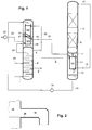
- gaseous feed air 1 which was previously compressed, cleaned and cooled to approximately dew point (not shown), is fed to the pressure column 2 immediately above the sump.
- the pressure column 2 is part of a rectification system, which also has a low pressure column 3 and a main condenser in the form of a condenser-evaporator system 101, 102, 103.
- the air is broken down into top nitrogen in the pressure column 2 and into an oxygen-enriched liquid.
- the latter is not drawn off from the sump as usual, but rather from theoretical or practical floors higher via line 5.
- the oxygen-enriched liquid 5 is fed into the low-pressure column via an unillustrated line at an intermediate point 3 throttled.
- the low pressure column 3 there are one or more in the upper area Nitrogen products withdrawn (not shown). Below the bottom Rectification section is oxygen in the purity required for the product won. It flows as the first oxygen-rich liquid from the bottom floor or packing section of the low pressure column 3 and is in one Collector 7 collected. The first oxygen-rich liquid continues to flow to the upper end of the first section 101 of the condenser-evaporator system and is introduced into its evaporation passages. The first section 101 is as Falling film evaporator trained. About 28 to 30% of the first evaporate there oxygen-rich liquid 7 in indirect heat exchange with a first part 8 the nitrogen-rich gas fraction 4 from the top of the pressure column 2. This condenses nitrogen-rich gas 8 to a first nitrogen-rich liquid 9.
- the vapor 11 that is in the first section 101 of the condenser-evaporator system generated flows back to the lowermost rectifying section of the low pressure column and participates in countercurrent mass transfer within this column.
- the liquid remaining portion 12 forms a second oxygen-rich liquid. This is about Line 13 withdrawn and by means of a pump 14 to the second section of the Condenser-evaporator performed by a combination of another Falling film evaporator 102 and a circulation evaporator 103 is formed as in EP 795349 A is described in detail.
- the second oxygen-rich liquid flows in the evaporation passages of the another falling film evaporator 102 down and evaporates there to about 40%.
- the steam 15 formed is completely fed into the low pressure column 3 via line 16 returned, since in the example no oxygen is released directly as a gaseous product is removed from the rectification system.
- the line 16 also serves for Keeping the liquid level in the liquid bath 18 constant by removing excess Liquid together with the vapor generated in the second section 102, 103 Low pressure column 3 is performed.
- the remaining liquid 17 from the section 102 flows into the liquid bath 18 of the circulation evaporator 103 and forms together with the liquid 19 knocked over in the circulation evaporator, a third oxygen-rich Liquid.
- This is obtained as an oxygen product by partially over Line 20 drawn off, internally compressed by means of a pump 21, to the known one Evaporated way under increased pressure and finally as a gaseous pressure product is brought out.
- the liquefied air stream 24 can an intermediate point are introduced into the pressure column 2.
- the liquefaction passages of the further falling film evaporator 102 and the Circulation evaporators 103 are designed continuously. You are from a second Part 22 of the nitrogen-rich gas fraction 4 from the pressure column 2 is applied. The Nitrogen first flows through the falling film evaporator 102 and then through the circulation evaporator 103 and condenses at least partially, preferably practically complete. The resulting second nitrogen-rich liquid 23 becomes completely abandoned as a return to the pressure column 2.
- FIG. 2 shows in detail the connection between line 16 and the outside space around the two condenser-evaporators 102, 103, which form the second section of the condenser-evaporator system.
- the dimensions of the line are essentially designed according to the amount of gas to be transported. It is arranged in such a way that liquid overflows from the liquid bath of the circulation evaporator 103 and can flow back as film 26 on the underside of the line 16 into the low-pressure column 3 or into the liquid sump below the first falling film evaporator 101. As a result, the liquid level of the liquid bath of the circulation evaporator 103 is kept at a constant level without special control measures.
- FIG. 3 differs from FIG. 1 by an additional line 301, via which part of the first nitrogen-rich liquid 9 can be fed as a return to the pressure column 2.
- a liquid pump 302 is necessary to overcome the static height between the first section 101 of the condenser-evaporator system and the upper region of the pressure column 2.
- more heating surface can be installed in the first section 101, which is designed here as a bottom evaporator of the low pressure column 3.
- less heating surface is required for the second section 102, 103, in the example at the head of the pressure column 2.
- This allows the spatial division of the condenser-evaporator system to be optimized. In many cases, the advantage of this optimization is greater than the expenditure for the additional line 301 and the liquid pump 302.
- the entire Heating surface of the section 102 can be integrated into the first section 101, so that the second section of the condenser-evaporator system consists of only one Circulation evaporator 103 exists.
Landscapes
- Engineering & Computer Science (AREA)
- Physics & Mathematics (AREA)
- Mechanical Engineering (AREA)
- Thermal Sciences (AREA)
- General Engineering & Computer Science (AREA)
- Health & Medical Sciences (AREA)
- Emergency Medicine (AREA)
- Separation By Low-Temperature Treatments (AREA)
Abstract
Description
Claims (13)
- Verfahren zur Tieftemperaturzerlegung von Luft, bei dem verdichtete und vorgereinigte Einsatzluft (1) in ein Rektifiziersystem zur Stickstoff-Sauerstoff-Trennung eingeleitet wird, daseine Drucksäule (2),eine Niederdrucksäule (3) undein Kondensator-Verdampfer-System (101, 102, 103) zur Beheizung der Niederdrucksäule (3)
aufweist, wobeidas Kondensator-Verdampfer-System einen ersten Abschnitt (101) aufweist, der als Fallfilmverdampfer ausgebildet ist,eine erste sauerstoffreiche Flüssigkeit (6) aus der Niederdrucksäule (3) in die Verdampfungspassagen des Fallfilmverdampfers (101) eingeleitet und dort teilweise verdampft wird, wobei ein sauerstoffreicher Dampf (11) und eine zweite sauerstoffreiche Flüssigkeit (12) gebildet werden, und wobeider sauerstoffreiche Dampf (11) mindestens zum Teil in die Niederdrucksäule (3) zurückgeleitet wird,
dadurch gekennzeichnet, daß das Kondensator-Verdampfer-System einen zweiten Abschnitt (102, 103) aufweist, der mindestens teilweise als Umlaufverdampfer (103) ausgebildet ist und daß die zweite sauerstoffreiche Flüssigkeit (12, 13) mindestens teilweise mittels einer Fördereinrichtung (14) zu den Verdampfungspassagen des zweiten Abschnitts (102, 103) des Kondensator-Verdampfer-Systems geleitet wird. - Verfahren nach Anspruch 1, dadurch gekennzeichnet, daß der in den Verdampfungspassagen des zweiten Abschnitts des Kondensator-Verdampfer-Systems erzeugte Dampf mindestens zur Hälfte in die Niederdrucksäule (3) eingeleitet (16) wird.
- Verfahren nach Anspruch 1 oder 2, dadurch gekennzeichnet, daß eine dritte sauerstoffreiche Flüssigkeit (18), die aus dem im zweiten Abschnitt (102, 103) des Kondensator-Verdampfer-Systems nicht verdampften Teil der zweiten sauerstoffreichen Flüssigkeit (12, 13) gebildet wird, mindestens teilweise in die Niederdrucksäule (3) und/oder zu den Verdampfungspassagen des ersten Abschnitts (101) des Kondensator-Verdampfer-Systems zurückgeleitet (16) wird.
- Verfahren nach einem der Ansprüche 1 bis 3, dadurch gekennzeichnet, daßim oberen Bereich der Drucksäule (2) eine stickstoffreiche Gasfraktion (4) erzeugt wird,ein erster Teil (8) der stickstoffreichen Gasfraktion (4) in die Verflüssigungspassagen des ersten Abschnitts (101) des Kondensator-Verdampfer-Systems eingeleitet und dort mindestens teilweise kondensiert wird, wobei eine erste stickstoffreiche Flüssigkeit (9) gebildet wird,ein zweiter Teil (22) der stickstoffreichen Gasfraktion (4) in die Verflüssigungspassagen des zweiten Abschnitts (102, 103) des Kondensator-Verdampfer-Systems eingeleitet und dort mindestens teilweise kondensiert wird, wobei eine zweite stickstoffreiche Flüssigkeit (23) gebildet wird,die erste stickstoffreiche Flüssigkeit (9) mindestens teilweise entspannt (10) und als Rücklauf auf die Niederdrucksäule (3) aufgegeben wird unddie zweite stickstoffreiche Flüssigkeit (23) mindestens teilweise als Rücklauf auf die Drucksäule (2) aufgegeben wird.
- Verfahren nach Anspruch 4, dadurch gekennzeichnet, daß ein Teil der ersten stickstoffreichen Flüssigkeit (9) als Rücklauf auf die Drucksäule (2) aufgegeben (301, 302) wird.
- Verfahren nach einem der Ansprüche 1 bis 5, dadurch gekennzeichnet, daß Drucksäule (2) und Niederdrucksäule (3) nebeneinander angeordnet sind, wobei der erste Abschnitt (101) des Kondensator-Verdampfer-Systems unterhalb des untersten Bodens beziehungsweise des untersten Packungsabschnitts der Niederdrucksäule (3) und/oder der zweite Abschnitt des Kondensator-Verdampfer-Systems oberhalb des obersten Bodens beziehungsweise des obersten Packungsabschnitts der Drucksäule (2) angeordnet sind.
- Verfahren nach einem der Ansprüche 1 bis 6, dadurch gekennzeichnet, daß der erste Abschnitt (101) des Kondensator-Verdampfer-Systems ausschließlich als Fallfilmverdampfer ausgebildet ist.
- Verfahren nach einem der Ansprüche 1 bis 7, dadurch gekennzeichnet, daß der zweite Abschnitt des Kondensator-Verdampfer-Systems durch mindestens zwei verdampfungsseitig seriell verbundene Teilabschnitte gebildet wird, von denen mindestens einer als Fallfilmverdampfer (102) und mindestens einer als Umlaufverdampfer (103) ausgebildet ist.
- Vorrichtung zur Tieftemperaturzerlegung von Luft mit einem Rektifiziersystem zur Stickstoff-Sauerstoff-Trennung, daseine Drucksäule (2),eine Niederdrucksäule (3) undein Kondensator-Verdampfer-System (101, 102, 103) zur Beheizung der Niederdrucksäule (3)
aufweist,wobei das Kondensator-Verdampfer-System einen ersten Abschnitt (101) aufweist, der als Fallfilmverdampfer ausgebildet ist,
und miteiner Einsatzluftleitung (1) zur Einleitung verdichteter und vorgereinigter Einsatzluft (1) in die Drucksäule (2),Mitteln zur Zuführung einer ersten sauerstoffreichen Flüssigkeit (6) aus der Niederdrucksäule (3) in die Verdampfungspassagen des Fallfilmverdampfers (101) undMitteln zur Rückführung von sauerstoffreichem Dampf (11) aus den Verdampfungspassagen des Fallfilmverdampfers (101) in die Niederdrucksäule (3),
dadurch gekennzeichnet, daß das Kondensator-Verdampfer-System einen zweiten Abschnitt (102, 103) aufweist, der mindestens teilweise als Umlaufverdampfer (103) ausgebildet ist und die Vorrichtung Mittel zur Einleitung einer zweiten sauerstoffreichen Flüssigkeit (12, 13) aus den Verdampfungspassagen des Fallfilmverdampfers (101) zu den Verdampfungspassagen des zweiten Abschnitts (102, 103) des Kondensator-Verdampfer-Systems aufweist, die eine Fördereinrichtung (14) umfassen. - Vorrichtung nach Anspruch 9, dadurch gekennzeichnet, daß Drucksäule (2) und Niederdrucksäule (3) nebeneinander angeordnet sind, wobei der erste Abschnitt (101) des Kondensator-Verdampfer-Systems unterhalb des untersten Bodens beziehungsweise des untersten Packungsabschnitts der Niederdrucksäule (3) und/oder der zweite Abschnitt des Kondensator-Verdampfer-Systems oberhalb des obersten Bodens beziehungsweise des obersten Packungsabschnitts der Drucksäule (2) angeordnet sind.
- Vorrichtung nach Anspruch 9 oder 10, dadurch gekennzeichnet, daß der erste Abschnitt (101) des Kondensator-Verdampfer-Systems ausschließlich als Fallfilmverdampfer ausgebildet ist.
- Vorrichtung nach einem der Ansprüche 9 bis 11, dadurch gekennzeichnet, daß der zweite Abschnitt des Kondensator-Verdampfer-Systems durch mindestens zwei verdampfungsseitig seriell verbundene Teilabschnitte gebildet wird, deren erster als Fallfilmverdampfer (102) und deren zweiter als Umlaufverdampfer (103) ausgebildet ist.
- Vorrichtung nach einem der Ansprüche 9 bis 11, dadurch gekennzeichnet, daß der Austritt (9) der Verflüssigungspassagen des ersten Abschnitts (101) des Kondensator-Verdampfer-Systems über eine Flüssigkeitsleitung (301) und gegebenenfalls über eine Flüssigpumpe (302) mit der Drucksäule (2) verbunden ist.
Priority Applications (1)
| Application Number | Priority Date | Filing Date | Title |
|---|---|---|---|
| EP00119941A EP1094286B1 (de) | 1999-10-20 | 2000-09-13 | Verfahren und Vorrichtung zur Tieftemperaturzerlegung von Luft |
Applications Claiming Priority (5)
| Application Number | Priority Date | Filing Date | Title |
|---|---|---|---|
| DE19950570A DE19950570A1 (de) | 1999-10-20 | 1999-10-20 | Verfahren und Vorrichtung zur Tieftemperaturzerlegung von Luft |
| DE19950570 | 1999-10-20 | ||
| EP00102564 | 2000-02-07 | ||
| EP00102564 | 2000-02-07 | ||
| EP00119941A EP1094286B1 (de) | 1999-10-20 | 2000-09-13 | Verfahren und Vorrichtung zur Tieftemperaturzerlegung von Luft |
Publications (2)
| Publication Number | Publication Date |
|---|---|
| EP1094286A1 true EP1094286A1 (de) | 2001-04-25 |
| EP1094286B1 EP1094286B1 (de) | 2005-06-15 |
Family
ID=34740582
Family Applications (1)
| Application Number | Title | Priority Date | Filing Date |
|---|---|---|---|
| EP00119941A Revoked EP1094286B1 (de) | 1999-10-20 | 2000-09-13 | Verfahren und Vorrichtung zur Tieftemperaturzerlegung von Luft |
Country Status (4)
| Country | Link |
|---|---|
| EP (1) | EP1094286B1 (de) |
| AT (1) | ATE298070T1 (de) |
| DE (1) | DE50010552D1 (de) |
| ES (1) | ES2243182T3 (de) |
Cited By (2)
| Publication number | Priority date | Publication date | Assignee | Title |
|---|---|---|---|---|
| EP1243882A1 (de) * | 2001-03-21 | 2002-09-25 | Linde Aktiengesellschaft | Argongewinnung mit einem Drei-Säulen-System zur Luftzerlegung und einer Rohargonsäule |
| EP3910274A1 (de) * | 2020-05-13 | 2021-11-17 | Linde GmbH | Verfahren zur tieftemperaturzerlegung von luft und luftzerlegungs anlage |
Citations (6)
| Publication number | Priority date | Publication date | Assignee | Title |
|---|---|---|---|---|
| US4006001A (en) * | 1974-01-18 | 1977-02-01 | Linde Aktiengesellschaft | Production of intermediate purity oxygen by plural distillation |
| EP0410832A1 (de) * | 1989-07-28 | 1991-01-30 | L'air Liquide, Societe Anonyme Pour L'etude Et L'exploitation Des Procedes Georges Claude | Verdampfer-Kondensator für eine Zweisäulenanlage zur Luftzerlegung |
| EP0469780A1 (de) * | 1990-07-31 | 1992-02-05 | The BOC Group plc | Tiefsieden von verflüssigtem Gas |
| EP0795349A1 (de) * | 1996-02-14 | 1997-09-17 | Linde Aktiengesellschaft | Vorrichtung und Verfahren zum Verdampfen einer Flüssigkeit |
| US5761927A (en) * | 1997-04-29 | 1998-06-09 | Air Products And Chemicals, Inc. | Process to produce nitrogen using a double column and three reboiler/condensers |
| US5775129A (en) * | 1997-03-13 | 1998-07-07 | The Boc Group, Inc. | Heat exchanger |
-
2000
- 2000-09-13 EP EP00119941A patent/EP1094286B1/de not_active Revoked
- 2000-09-13 AT AT00119941T patent/ATE298070T1/de active
- 2000-09-13 DE DE50010552T patent/DE50010552D1/de not_active Revoked
- 2000-09-13 ES ES00119941T patent/ES2243182T3/es not_active Expired - Lifetime
Patent Citations (6)
| Publication number | Priority date | Publication date | Assignee | Title |
|---|---|---|---|---|
| US4006001A (en) * | 1974-01-18 | 1977-02-01 | Linde Aktiengesellschaft | Production of intermediate purity oxygen by plural distillation |
| EP0410832A1 (de) * | 1989-07-28 | 1991-01-30 | L'air Liquide, Societe Anonyme Pour L'etude Et L'exploitation Des Procedes Georges Claude | Verdampfer-Kondensator für eine Zweisäulenanlage zur Luftzerlegung |
| EP0469780A1 (de) * | 1990-07-31 | 1992-02-05 | The BOC Group plc | Tiefsieden von verflüssigtem Gas |
| EP0795349A1 (de) * | 1996-02-14 | 1997-09-17 | Linde Aktiengesellschaft | Vorrichtung und Verfahren zum Verdampfen einer Flüssigkeit |
| US5775129A (en) * | 1997-03-13 | 1998-07-07 | The Boc Group, Inc. | Heat exchanger |
| US5761927A (en) * | 1997-04-29 | 1998-06-09 | Air Products And Chemicals, Inc. | Process to produce nitrogen using a double column and three reboiler/condensers |
Cited By (5)
| Publication number | Priority date | Publication date | Assignee | Title |
|---|---|---|---|---|
| EP1243882A1 (de) * | 2001-03-21 | 2002-09-25 | Linde Aktiengesellschaft | Argongewinnung mit einem Drei-Säulen-System zur Luftzerlegung und einer Rohargonsäule |
| EP1243881A1 (de) * | 2001-03-21 | 2002-09-25 | Linde Aktiengesellschaft | Drei-Säulen-System zur Tieftemperatur-Luftzerlegung |
| US6530242B2 (en) | 2001-03-21 | 2003-03-11 | Linde Aktiengesellschaft | Obtaining argon using a three-column system for the fractionation of air and a crude argon column |
| US6564581B2 (en) | 2001-03-21 | 2003-05-20 | Linde Aktiengesellschaft | Three-column system for the low-temperature fractionation of air |
| EP3910274A1 (de) * | 2020-05-13 | 2021-11-17 | Linde GmbH | Verfahren zur tieftemperaturzerlegung von luft und luftzerlegungs anlage |
Also Published As
| Publication number | Publication date |
|---|---|
| DE50010552D1 (de) | 2005-07-21 |
| EP1094286B1 (de) | 2005-06-15 |
| ATE298070T1 (de) | 2005-07-15 |
| ES2243182T3 (es) | 2005-12-01 |
Similar Documents
| Publication | Publication Date | Title |
|---|---|---|
| EP1243882B1 (de) | Argongewinnung mit einem Drei-Säulen-System zur Luftzerlegung und einer Rohargonsäule | |
| EP1308680B1 (de) | Verfahren und Vorrichtung zur Gewinnung von Krypton und/oder Xenon durch Tieftemperaturzerlegung von Luft | |
| EP2235460B1 (de) | Verfahren und vorrichtung zur tieftemperatur-luftzerlegung | |
| EP1482266B1 (de) | Verfahren und Vorrichtung zur Gewinnung von Krypton und/oder Xenon durch Tieftemperaturzerlegung von Luft | |
| EP1376037B1 (de) | Luftzerlegungsverfahren und -anlage mit Mischsäule und Krypton-Xenon-Gewinnung | |
| EP0669509A1 (de) | Verfahren und Vorrichtung zur Gewinnung von reinem Argon | |
| DE10334559A1 (de) | Verfahren und Vorrichtung zur Gewinnung von Krypton und/oder Xenon durch Tieftemperaturzerlegung von Luft | |
| WO2020169257A1 (de) | Verfahren und anlage zur tieftemperaturzerlegung von luft | |
| DE10332863A1 (de) | Verfahren und Vorrichtung zur Gewinnung von Krypton und/oder Xenon durch Tieftemperaturzerlegung von Luft | |
| EP1051588B1 (de) | Verfahren und vorrichtung zum verdampfen von flüssigem sauerstoff | |
| DE10302389A1 (de) | Verfahren und Vorrichtung zur Tieftemperaturzerlegung von Luft | |
| WO2016146246A1 (de) | Anlage zur erzeugung von sauerstoff durch tieftemperaturzerlegung von luft | |
| EP0768503A2 (de) | Dreifachsäulenverfahren zur Tieftemperaturzerlegung von Luft | |
| EP3980705A1 (de) | Verfahren und anlage zur tieftemperaturzerlegung von luft | |
| DE102005040508A1 (de) | Verfahren zur Gewinnung von Krypton und/oder Xenon durch Tieftemperaturzerlegung von Luft | |
| DE19950570A1 (de) | Verfahren und Vorrichtung zur Tieftemperaturzerlegung von Luft | |
| EP3067649A1 (de) | Destillationssäulen-system und verfahren zur erzeugung von sauerstoff durch tieftemperaturzerlegung von luft | |
| EP1231440A1 (de) | Verfahren und Vorrichtung zur Tieftemperaturzerlegung von Luft | |
| DE10232430A1 (de) | Verfahren und Vorrichtung zur Gewinnung von Krypton und/oder Xenon durch Tieftemperaturzerlegung von Luft | |
| EP1094286B1 (de) | Verfahren und Vorrichtung zur Tieftemperaturzerlegung von Luft | |
| DE10153919A1 (de) | Verfahren und Vorrichtung zur Gewinnung hoch reinen Sauerstoffs aus weniger reinem Sauerstoff | |
| WO2014067662A2 (de) | Verfahren zur tieftemperaturzerlegung von luft in einer luftzerlegungsanlage und luftzerlegungsanlage | |
| DE10152356A1 (de) | Verfahren und Vorrichtung zur Gewinnung von Argon und hoch reinem Sauerstoff durch Tieftemperatur-Zerlegung | |
| DE20319823U1 (de) | Vorrichtung zur Gewinnung von Krypton und/oder Xenon durch Tieftemperaturzerlegung | |
| DE60019198T2 (de) | Vorrichtung und Verfahren zur Luftzerlegung durch Tieftemperaturrektifikation |
Legal Events
| Date | Code | Title | Description |
|---|---|---|---|
| PUAI | Public reference made under article 153(3) epc to a published international application that has entered the european phase |
Free format text: ORIGINAL CODE: 0009012 |
|
| AK | Designated contracting states |
Kind code of ref document: A1 Designated state(s): AT BE CH CY DE DK ES FI FR GB GR IE IT LI LU MC NL PT SE |
|
| AX | Request for extension of the european patent |
Free format text: AL;LT;LV;MK;RO;SI |
|
| 17P | Request for examination filed |
Effective date: 20010928 |
|
| AKX | Designation fees paid |
Free format text: AT BE CH CY DE DK ES FI FR GB GR IE IT LI LU MC NL PT SE |
|
| 17Q | First examination report despatched |
Effective date: 20030521 |
|
| GRAP | Despatch of communication of intention to grant a patent |
Free format text: ORIGINAL CODE: EPIDOSNIGR1 |
|
| GRAS | Grant fee paid |
Free format text: ORIGINAL CODE: EPIDOSNIGR3 |
|
| GRAA | (expected) grant |
Free format text: ORIGINAL CODE: 0009210 |
|
| AK | Designated contracting states |
Kind code of ref document: B1 Designated state(s): AT BE CH CY DE DK ES FI FR GB GR IE IT LI LU MC NL PT SE |
|
| PG25 | Lapsed in a contracting state [announced via postgrant information from national office to epo] |
Ref country code: IE Free format text: LAPSE BECAUSE OF FAILURE TO SUBMIT A TRANSLATION OF THE DESCRIPTION OR TO PAY THE FEE WITHIN THE PRESCRIBED TIME-LIMIT Effective date: 20050615 Ref country code: FI Free format text: LAPSE BECAUSE OF FAILURE TO SUBMIT A TRANSLATION OF THE DESCRIPTION OR TO PAY THE FEE WITHIN THE PRESCRIBED TIME-LIMIT Effective date: 20050615 |
|
| REG | Reference to a national code |
Ref country code: GB Ref legal event code: FG4D Free format text: NOT ENGLISH Ref country code: CH Ref legal event code: EP |
|
| REF | Corresponds to: |
Ref document number: 50010552 Country of ref document: DE Date of ref document: 20050721 Kind code of ref document: P |
|
| REG | Reference to a national code |
Ref country code: IE Ref legal event code: FG4D Free format text: LANGUAGE OF EP DOCUMENT: GERMAN |
|
| PG25 | Lapsed in a contracting state [announced via postgrant information from national office to epo] |
Ref country code: CY Free format text: LAPSE BECAUSE OF FAILURE TO SUBMIT A TRANSLATION OF THE DESCRIPTION OR TO PAY THE FEE WITHIN THE PRESCRIBED TIME-LIMIT Effective date: 20050913 |
|
| PG25 | Lapsed in a contracting state [announced via postgrant information from national office to epo] |
Ref country code: DK Free format text: LAPSE BECAUSE OF FAILURE TO SUBMIT A TRANSLATION OF THE DESCRIPTION OR TO PAY THE FEE WITHIN THE PRESCRIBED TIME-LIMIT Effective date: 20050915 Ref country code: GR Free format text: LAPSE BECAUSE OF FAILURE TO SUBMIT A TRANSLATION OF THE DESCRIPTION OR TO PAY THE FEE WITHIN THE PRESCRIBED TIME-LIMIT Effective date: 20050915 |
|
| REG | Reference to a national code |
Ref country code: SE Ref legal event code: TRGR |
|
| PG25 | Lapsed in a contracting state [announced via postgrant information from national office to epo] |
Ref country code: LU Free format text: LAPSE BECAUSE OF NON-PAYMENT OF DUE FEES Effective date: 20050930 Ref country code: MC Free format text: LAPSE BECAUSE OF NON-PAYMENT OF DUE FEES Effective date: 20050930 Ref country code: CH Free format text: LAPSE BECAUSE OF NON-PAYMENT OF DUE FEES Effective date: 20050930 Ref country code: LI Free format text: LAPSE BECAUSE OF NON-PAYMENT OF DUE FEES Effective date: 20050930 |
|
| GBT | Gb: translation of ep patent filed (gb section 77(6)(a)/1977) |
Effective date: 20050926 |
|
| PG25 | Lapsed in a contracting state [announced via postgrant information from national office to epo] |
Ref country code: PT Free format text: LAPSE BECAUSE OF FAILURE TO SUBMIT A TRANSLATION OF THE DESCRIPTION OR TO PAY THE FEE WITHIN THE PRESCRIBED TIME-LIMIT Effective date: 20051124 |
|
| REG | Reference to a national code |
Ref country code: ES Ref legal event code: FG2A Ref document number: 2243182 Country of ref document: ES Kind code of ref document: T3 |
|
| REG | Reference to a national code |
Ref country code: IE Ref legal event code: FD4D |
|
| PLBI | Opposition filed |
Free format text: ORIGINAL CODE: 0009260 |
|
| ET | Fr: translation filed | ||
| PLAX | Notice of opposition and request to file observation + time limit sent |
Free format text: ORIGINAL CODE: EPIDOSNOBS2 |
|
| 26 | Opposition filed |
Opponent name: L'AIR LIQUIDE, S.A. A DIRECTOIRE ET CONSEIL DE S Effective date: 20060315 |
|
| REG | Reference to a national code |
Ref country code: CH Ref legal event code: PL |
|
| NLR1 | Nl: opposition has been filed with the epo |
Opponent name: L'AIR LIQUIDE, S.A. A DIRECTOIRE ET CONSEIL DE SUR |
|
| PLAF | Information modified related to communication of a notice of opposition and request to file observations + time limit |
Free format text: ORIGINAL CODE: EPIDOSCOBS2 |
|
| PLBB | Reply of patent proprietor to notice(s) of opposition received |
Free format text: ORIGINAL CODE: EPIDOSNOBS3 |
|
| RDAF | Communication despatched that patent is revoked |
Free format text: ORIGINAL CODE: EPIDOSNREV1 |
|
| APBP | Date of receipt of notice of appeal recorded |
Free format text: ORIGINAL CODE: EPIDOSNNOA2O |
|
| APAH | Appeal reference modified |
Free format text: ORIGINAL CODE: EPIDOSCREFNO |
|
| BECA | Be: change of holder's address |
Owner name: *LINDE A.G.LEOPOLDSTRASSE 252, D-80807 MUENCHEN Effective date: 20050615 |
|
| APAH | Appeal reference modified |
Free format text: ORIGINAL CODE: EPIDOSCREFNO |
|
| APBQ | Date of receipt of statement of grounds of appeal recorded |
Free format text: ORIGINAL CODE: EPIDOSNNOA3O |
|
| REG | Reference to a national code |
Ref country code: FR Ref legal event code: CA |
|
| PGFP | Annual fee paid to national office [announced via postgrant information from national office to epo] |
Ref country code: AT Payment date: 20080912 Year of fee payment: 9 Ref country code: FR Payment date: 20080915 Year of fee payment: 9 Ref country code: IT Payment date: 20080926 Year of fee payment: 9 Ref country code: NL Payment date: 20080903 Year of fee payment: 9 |
|
| PGFP | Annual fee paid to national office [announced via postgrant information from national office to epo] |
Ref country code: GB Payment date: 20080917 Year of fee payment: 9 |
|
| PGFP | Annual fee paid to national office [announced via postgrant information from national office to epo] |
Ref country code: DE Payment date: 20080926 Year of fee payment: 9 |
|
| PGFP | Annual fee paid to national office [announced via postgrant information from national office to epo] |
Ref country code: BE Payment date: 20080922 Year of fee payment: 9 Ref country code: ES Payment date: 20081021 Year of fee payment: 9 Ref country code: SE Payment date: 20080908 Year of fee payment: 9 |
|
| RAP2 | Party data changed (patent owner data changed or rights of a patent transferred) |
Owner name: LINDE AG |
|
| NLT2 | Nl: modifications (of names), taken from the european patent patent bulletin |
Owner name: LINDE AG Effective date: 20090819 |
|
| APBU | Appeal procedure closed |
Free format text: ORIGINAL CODE: EPIDOSNNOA9O |
|
| RDAG | Patent revoked |
Free format text: ORIGINAL CODE: 0009271 |
|
| STAA | Information on the status of an ep patent application or granted ep patent |
Free format text: STATUS: PATENT REVOKED |
|
| 27W | Patent revoked |
Effective date: 20100218 |
|
| GBPR | Gb: patent revoked under art. 102 of the ep convention designating the uk as contracting state |
Effective date: 20100218 |
|
| REG | Reference to a national code |
Ref country code: SE Ref legal event code: ECNC |
|
| PG25 | Lapsed in a contracting state [announced via postgrant information from national office to epo] |
Ref country code: IT Free format text: LAPSE BECAUSE OF NON-PAYMENT OF DUE FEES Effective date: 20090913 |
|
| PG25 | Lapsed in a contracting state [announced via postgrant information from national office to epo] |
Ref country code: ES Free format text: LAPSE BECAUSE OF NON-PAYMENT OF DUE FEES Effective date: 20090914 |