EP1093977A1 - Vehicle steering wheel - Google Patents
Vehicle steering wheel Download PDFInfo
- Publication number
- EP1093977A1 EP1093977A1 EP00122310A EP00122310A EP1093977A1 EP 1093977 A1 EP1093977 A1 EP 1093977A1 EP 00122310 A EP00122310 A EP 00122310A EP 00122310 A EP00122310 A EP 00122310A EP 1093977 A1 EP1093977 A1 EP 1093977A1
- Authority
- EP
- European Patent Office
- Prior art keywords
- steering wheel
- switch
- vehicle steering
- wheel according
- bearing part
- Prior art date
- Legal status (The legal status is an assumption and is not a legal conclusion. Google has not performed a legal analysis and makes no representation as to the accuracy of the status listed.)
- Granted
Links
Images

Classifications
-
- B—PERFORMING OPERATIONS; TRANSPORTING
- B60—VEHICLES IN GENERAL
- B60Q—ARRANGEMENT OF SIGNALLING OR LIGHTING DEVICES, THE MOUNTING OR SUPPORTING THEREOF OR CIRCUITS THEREFOR, FOR VEHICLES IN GENERAL
- B60Q5/00—Arrangement or adaptation of acoustic signal devices
- B60Q5/001—Switches therefor
- B60Q5/003—Switches therefor mounted on the steering wheel
Definitions
- the invention relates to a vehicle steering wheel, with a switch, which is movably mounted on the steering wheel, with a storage for the Switches, which a guide part and a surrounding the guide part Has storage part.
- Vehicle steering wheels are increasingly used with switches, the the largest switch in terms of area is the horn switch.
- the horn switch is aimed at that after Overcoming the usually provided pre-tension easily movable is.
- the invention provides a vehicle steering wheel in which the friction the movement of the guide part to the storage part is kept low.
- a vehicle steering wheel of the type mentioned achieved that the guide member has a free end with a free end, transverse to the direction of movement of the switch to the outside has expanding cone, with the end in the unactuated Switch position forms an end stop and on the bearing part is present.
- the cone-shaped end that puts the switch in its end position stops in the direction opposite to the direction of movement is achieved that with minimal actuation of the switch, the end of Bearing part completely detaches and almost no friction is present between the storage part and the guide part. Tilting too of the guide part and the bearing part can be prevented, such as this with a cylindrical free end that is in a cylindrical Sleeve is stored, could occur.
- the bearing part preferably also has a conical shape Contact surface against which the cone lies, which leads to an immediate, quick release of the adjacent surfaces when actuated leads.
- the full area system in the end stop is achieved in that the contact surface of the bearing part complementary to the conical End stop is formed.
- the switch is preferably on an airbag module housing stored, and so completely stored that switch and gas bag module housing form a separate pre-assembled unit, which then in the preferably foamed steering wheel skeleton is used.
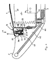
- FIG. 1 shows a vehicle steering wheel that is close to the steering wheel 3 and a steering wheel rim 5.
- the steering wheel hub is in lower area is provided in one piece with the steering wheel rim, front module cover 7 shown.
- the horn switch has a externally touchable actuator 14 with an outer Actuating surface 15.
- the cover 7 is the upper part 43 of a Airbag module housing 23, in which a gas generator 24 and an airbag 25 are housed.
- the operating surface is on the front 15 of the horn switch 13 is slightly opposite the module cover 7 in front.
- the horn switch 13 is motion decoupled from the cover.
- the interior of the gas bag module housing 23 forms a receiving space 27 for gas generator 24 and gas bag 25.
- linear bearings 45 are provided, of which only the is shown front and both attached to the actuator 14 are.
- the linear bearings 45 each consist of a bearing part 47 in the form of a single piece on the cover, more precisely on the upper part 43 molded hat-shaped lateral extension 48 and one by Protruding part on the underside of the actuating surface 15 screwed guide part 49.
- the guide part 49 has a upper end with a thread, which in a threaded bushing 51 in the Actuator 14 is screwed.
- the guide part 49 an opposite, lower free end 53 with a to the free end transverse to the direction of movement A of the horn switch cone widening outwards.
- the conical end 53 lies on one Complementally designed contact surface on the bearing part in the unactuated Switch position according to Figure 1 over the entire surface. Between the largest cross section of the conical end 53 and a peripheral wall 55 of the storage part there is play. On the underside of the peripheral wall 55, a cover 57 is attached to the mounting part 47, so that a space between the underside of the free end 53 and the cover 57 to accommodate a compression spring 59 arises.
- the pin-like is from below Guide part 49 inserted through the storage part 47 and into the threaded bush 51 screwed. Then the compression spring 49 in the associated room pressed and closed the room with the cover 57.
- the horn switch 13 is now completely on the module housing 23 stored.
- the unity formed in this way is finally integrated into the foamed steering wheel skeleton 63 inserted and fasteners, not shown detachably attached to it.
- the foam 62 of the steering wheel skeleton 63 with a corresponding one Provided recess 65 which includes the insertion of the storage part 47 Lid 57 allowed from above.
- the compression spring 59 ensures a defined unactuated switch position, by the guide part with its conical end, which forms an end stop against the contact surface of the bearing part 47 presses.
- the conical shape is released End 53 immediately completely of the storage part 47, so that no canting and no static friction occurs and the horn switch can be easily operated against even pressure.
- the Horn signal sounds as soon as the metal threaded bushing 51 two electrical Contacts 100 and 102 connects.
- the switch has 13 instead of contacts 100, 102 an electrical switching element, which is from the rear of the actuating element 14 is actuated.
- Switch 104 is positively embedded in a recess in the extension 48.
Abstract
Description
Die Erfindung betrifft ein Fahrzeuglenkrad, mit einem Schalter, der am Lenkrad beweglich gelagert ist, mit einer Lagerung für den Schalter, die ein Führungsteil und ein das Führungsteil umschließendes Lagerungsteil hat.The invention relates to a vehicle steering wheel, with a switch, which is movably mounted on the steering wheel, with a storage for the Switches, which a guide part and a surrounding the guide part Has storage part.
Fahrzeuglenkräder werden zunehmend mit Schaltern belegt, wobei der flächenmäßig größte Schalter der Hupenschalter ist.Vehicle steering wheels are increasingly used with switches, the the largest switch in terms of area is the horn switch.
Insbesondere beim Hupenschalter wird angestrebt, daß dieser nach Überwindung der üblicherweise vorgesehenen Vorspannung leicht beweglich ist.In particular, the horn switch is aimed at that after Overcoming the usually provided pre-tension easily movable is.
Die Erfindung schafft ein Fahrzeuglenkrad, bei dem die Reibung bei der Bewegung des Führungsteils zum Lagerungsteil gering gehalten wird. Dies wird bei einem Fahrzeuglenkrad der eingangs genannten Art dadurch erreicht, daß das Führungsteil ein freies Ende mit einem sich zum freien Ende, quer zur Bewegungsrichtung des Schalters nach außen erweiternden Konus aufweist, wobei das Ende in der unbetätigten Schalterstellung einen Endanschlag bildet und am Lagerungsteil anliegt. Durch das konusförmige Ende, das den Schalter in seine Endstellung in Richtung entgegen der Bewegungsrichtung hält, wird erreicht, daß bei minimaler Betätigung des Schalters sich das Ende vom Lagerungsteil vollständig löst und so gut wie keine Reibung mehr zwischen Lagerungsteil und Führungsteil vorhanden ist. Auch ein Verkanten von Führungsteil und Lagerungsteil kann verhindert werden, wie dies bei einem zylinderförmigen freien Ende, das in einer zylindrischen Hülse gelagert ist, auftreten könnte.The invention provides a vehicle steering wheel in which the friction the movement of the guide part to the storage part is kept low. This is in a vehicle steering wheel of the type mentioned achieved that the guide member has a free end with a free end, transverse to the direction of movement of the switch to the outside has expanding cone, with the end in the unactuated Switch position forms an end stop and on the bearing part is present. Through the cone-shaped end that puts the switch in its end position stops in the direction opposite to the direction of movement is achieved that with minimal actuation of the switch, the end of Bearing part completely detaches and almost no friction is present between the storage part and the guide part. Tilting too of the guide part and the bearing part can be prevented, such as this with a cylindrical free end that is in a cylindrical Sleeve is stored, could occur.
Vorzugsweise hat das Lagerungsteil ebenfalls eine konusförmige Anlagefläche, an der der Konus anliegt, was zu einem unmittelbaren, schnellen Lösen der aneinander anliegenden Flächen bei der Betätigung führt.The bearing part preferably also has a conical shape Contact surface against which the cone lies, which leads to an immediate, quick release of the adjacent surfaces when actuated leads.
Die vollflächige Anlage im Endanschlag wird dadurch erreicht, daß die Anlagefläche des Lagerungsteils komplementär zum konusförmigen Endanschlag ausgebildet ist.The full area system in the end stop is achieved in that the contact surface of the bearing part complementary to the conical End stop is formed.
Vorzugsweise ist quer zur Bewegungsrichtung ein Spiel zwischen dem Lagerungsteil und dem Endanschlag vorgesehen, das sicherstellen soll, daß tatsächlich unmittelbar nach der Betätigung ein Kontakt zwischen Führungsteil und Lagerungsteil vermieden wird.There is preferably a play between the transverse to the direction of movement Storage part and the end stop provided, which is to ensure that actually a contact between immediately after actuation Guide part and storage part is avoided.
Der Schalter ist vorzugsweise an einem Gassack-Modulgehäuse gelagert, und zwar so vollständig gelagert, daß Schalter und Gassack-Modulgehäuse eine separate vormontierte Einheit bilden, die dann in das vorzugsweise umschäumte Lenkradskelett eingesetzt wird.The switch is preferably on an airbag module housing stored, and so completely stored that switch and gas bag module housing form a separate pre-assembled unit, which then in the preferably foamed steering wheel skeleton is used.
Weitere Merkmale und Vorteile der Erfindung ergeben sich aus der
nachfolgenden Beschreibung und aus den nachfolgenden Zeichnungen, auf
die Bezug genommen wird. In den Zeichnungen zeigen:
In Figur 1 ist ein Fahrzeuglenkrad dargestellt, das eine Lenkradnahe
3 und einen Lenkradkranz 5 aufweist. In der Lenkradnabe ist im
unteren Bereich eine einstückig mit dem Lenkradkranz vorgesehene,
vorderseitige Modulabdeckung 7 dargestellt. An der Lenkradnabe sind
mehrere Schalter befestigt, zum Beispiel zur Telefon- oder
Radiobetätigung, sowie ein Hupenschalter 13. Der Hupenschalter hat ein
von außen berührbares Betätigungselement 14 mit einer äußeren
Betätigungsfläche 15. Die Abdeckung 7 ist das Oberteil 43 eines
Gassack-Modulgehäuses 23, in dem ein Gasgenerator 24 und ein Gassack
25 untergebracht sind. Zur Vorderseite hin steht die Betätigungsfläche
15 des Hupenschalters 13 geringfügig gegenüber der Modulabdeckung 7
vor. Der Hupenschalter 13 ist von der Abdeckung bewegungsentkoppelt.
Das Innere des Gassack-Modulgehäuses 23 bildet einen Aufnahmeraum 27
für Gasgenerator 24 und Gassack 25.FIG. 1 shows a vehicle steering wheel that is close to the
Im Bereich des oberen Randes der Betätigungsfläche 15, seitlich
des Aufnahmeraums 27 und am Oberteil 43 des Gassack-Modulgehäuses 23
sind zwei gleiche Linearlagerungen 45 vorgesehen, von denen nur die
vordere gezeigt ist und die beide am Betätigungselement 14 befestigt
sind. Die Linearlagerungen 45 bestehen jeweils aus einem Lagerungsteil
47 in Form eines einstückig an der Abdeckung, genauer am Oberteil 43
angeformten hutförmigen seitlichen Fortsatzes 48 und einem durch das
Lagerungsteil hindurchragenden, an der Unterseite der Betätigungsfläche
15 angeschraubten Führungsteils 49. Das Führungsteil 49 hat ein
oberes Ende mit einem Gewinde, welches in eine Gewindebuchse 51 in dem
Betätigungselement 14 eingeschraubt ist. Darüber hinaus hat das Führungsteil
49 ein entgegengesetztes, unteres freies Ende 53 mit einem
sich zum freien Ende quer zur Bewegungsrichtung A des Hupenschalters
nach außen erweiternden Konus. Das konusförmige Ende 53 liegt an einer
komplementär ausgeführten Anlagefläche am Lagerungsteil in der unbetätigten
Schalterstellung gemäß Figur 1 vollflächig an. Zwischen dem
größten Querschnitt des konusförmigen Endes 53 und einer Umfangswand
55 des Lagerungsteils besteht Spiel. Auf der Unterseite der Umfangswand
55 ist ein Deckel 57 am Lagerungsteil 47 angebracht, so daß
zwischen der Unterseite des freien Endes 53 und dem Deckel 57 ein Raum
zur Unterbringung einer Druckfeder 59 entsteht. Laterally in the area of the upper edge of the actuating
Zur Montage des Hupenschalters 13 wird von unten das stiftartige
Führungsteil 49 durch das Lagerungsteil 47 gesteckt und in die Gewindebuchse
51 geschraubt. Anschließend wird die Druckfeder 49 in den
zugehörigen Raum gedrückt und der Raum mit dem Deckel 57 verschlossen.To mount the
Der Hupenschalter 13 ist nun vollständig am Modulgehäuse 23
gelagert. Die so gebildete Einheit wird schließlich von oben in das
umschäumte Lenkradskelett 63 gesteckt und über nicht gezeigte Befestigungsmittel
an ihm lösbar angebracht. Im Bereich der Lenkradnabe ist
die Umschäumung 62 des Lenkradskeletts 63 mit einer entsprechenden
Ausnehmung 65 versehen, die das Einschieben des Lagerungsteils 47 samt
Deckel 57 von oben erlaubt.The
Die Druckfeder 59 sorgt für eine definierte unbetätigte Schalterstellung,
indem sie das Führungsteil mit seinem konusförmigen Ende,
welches einen Endanschlag bildet, gegen die Anlagefläche des Lagerteils
47 drückt.The
Bei der Betätigung des Hupenschalters 13 löst sich das konusförmige
Ende 53 sofort vollständig von dem Lagerungsteil 47, so daß
kein Verkanten und keine Haftreibung auftritt und der Hupenschalter
leicht gegen einen gleichmäßigen Druck betätigt werden kann. Das
Hupensignal ertönt, sobald die metallene Gewindebuchse 51 zwei elektrische
Kontakte 100 und 102 verbindet.When the
Wird der Gasgenerator betätigt, entfaltet sich der Gassack 25 und
reißt die vorderseitige Modulabdeckung 7 auf.If the gas generator is actuated, the
Bei der Ausführungsform nach Figur 2 hat der Schalter 13 anstatt
der Kontakte 100, 102 ein elektrisches Schaltglied, das von der Rückseite
des Betätigungselements 14 betätigt wird. Das Schaltglied 104
ist in eine Ausnehmung im Fortsatz 48 formschlüssig eingebettet.In the embodiment according to FIG. 2, the switch has 13 instead
of
Claims (10)
dadurch gekennzeichnet, daß
characterized in that
Applications Claiming Priority (2)
| Application Number | Priority Date | Filing Date | Title |
|---|---|---|---|
| DE29918483U | 1999-10-21 | ||
| DE29918483U DE29918483U1 (en) | 1999-10-21 | 1999-10-21 | Vehicle steering wheel |
Publications (2)
| Publication Number | Publication Date |
|---|---|
| EP1093977A1 true EP1093977A1 (en) | 2001-04-25 |
| EP1093977B1 EP1093977B1 (en) | 2003-07-23 |
Family
ID=8080528
Family Applications (1)
| Application Number | Title | Priority Date | Filing Date |
|---|---|---|---|
| EP00122310A Expired - Lifetime EP1093977B1 (en) | 1999-10-21 | 2000-10-20 | Vehicle steering wheel |
Country Status (4)
| Country | Link |
|---|---|
| US (1) | US6426473B1 (en) |
| EP (1) | EP1093977B1 (en) |
| DE (2) | DE29918483U1 (en) |
| ES (1) | ES2201987T3 (en) |
Families Citing this family (12)
| Publication number | Priority date | Publication date | Assignee | Title |
|---|---|---|---|---|
| SE517015C2 (en) * | 2000-07-14 | 2002-04-02 | Volvo Personvagnar Ab | Mounting module intended for a steering wheel in a vehicle and the procedure for mounting it |
| DE20105002U1 (en) | 2001-03-22 | 2001-07-26 | Trw Automotive Safety Sys Gmbh | Vehicle steering device |
| DE20112719U1 (en) * | 2001-08-01 | 2001-12-13 | Trw Automotive Safety Sys Gmbh | Steering wheel with movable gas bag module |
| DE20116306U1 (en) * | 2001-10-05 | 2002-02-14 | Trw Automotive Safety Sys Gmbh | vehicle steering wheel |
| EP1415857A2 (en) * | 2002-10-30 | 2004-05-06 | TRW Automotive Safety Systems GmbH | Vehicle steering wheel |
| DE20216755U1 (en) * | 2002-10-30 | 2003-03-20 | Trw Automotive Safety Sys Gmbh | steering wheel |
| US7077427B2 (en) * | 2003-07-16 | 2006-07-18 | Autoliv Asp, Inc. | Steering wheel assembly |
| DE102005019749B3 (en) * | 2005-04-28 | 2006-12-28 | Autoliv Development Ab | steering wheel |
| WO2008060193A1 (en) * | 2006-11-13 | 2008-05-22 | Autoliv Development Ab | An air-bag cover arrangement |
| TWI385090B (en) * | 2008-12-31 | 2013-02-11 | Metal Ind Res & Dev Ct | The Construction of Multi - modal Fixed - axis Steering Wheel and Its Control Method |
| DE102009030149B3 (en) | 2009-06-19 | 2010-12-30 | Takata-Petri Ag | Airbag module for a vehicle occupant restraint system |
| DE102009030151B3 (en) | 2009-06-19 | 2010-12-09 | Takata-Petri Ag | Airbag module for a vehicle occupant restraint system |
Citations (1)
| Publication number | Priority date | Publication date | Assignee | Title |
|---|---|---|---|---|
| US5957489A (en) * | 1995-02-27 | 1999-09-28 | Toyoda Gosei Co., Ltd. | Steering wheel |
Family Cites Families (6)
| Publication number | Priority date | Publication date | Assignee | Title |
|---|---|---|---|---|
| JPS60117238U (en) * | 1984-01-18 | 1985-08-08 | 日本プラスト株式会社 | steering wheel |
| US4872364A (en) * | 1987-10-27 | 1989-10-10 | Toyoda Gosei Co., Ltd. | Steering wheel |
| US5228362A (en) * | 1992-06-26 | 1993-07-20 | Chrysler Corporation | Vehicle steering wheel structure |
| JP3123166B2 (en) * | 1991-12-17 | 2001-01-09 | タカタ株式会社 | Module cover for airbag device |
| DE29720079U1 (en) * | 1997-11-12 | 1998-07-02 | Trw Repa Gmbh | Vehicle steering wheel with integrated gas bag module |
| DE29805210U1 (en) * | 1998-03-23 | 1998-06-04 | Trw Automotive Safety Sys Gmbh | Impact protection device |
-
1999
- 1999-10-21 DE DE29918483U patent/DE29918483U1/en not_active Expired - Lifetime
-
2000
- 2000-10-20 EP EP00122310A patent/EP1093977B1/en not_active Expired - Lifetime
- 2000-10-20 US US09/693,667 patent/US6426473B1/en not_active Expired - Fee Related
- 2000-10-20 DE DE50002973T patent/DE50002973D1/en not_active Expired - Lifetime
- 2000-10-20 ES ES00122310T patent/ES2201987T3/en not_active Expired - Lifetime
Patent Citations (1)
| Publication number | Priority date | Publication date | Assignee | Title |
|---|---|---|---|---|
| US5957489A (en) * | 1995-02-27 | 1999-09-28 | Toyoda Gosei Co., Ltd. | Steering wheel |
Also Published As
| Publication number | Publication date |
|---|---|
| EP1093977B1 (en) | 2003-07-23 |
| US6426473B1 (en) | 2002-07-30 |
| DE29918483U1 (en) | 2000-03-02 |
| DE50002973D1 (en) | 2003-08-28 |
| ES2201987T3 (en) | 2004-04-01 |
Similar Documents
| Publication | Publication Date | Title |
|---|---|---|
| EP1093977B1 (en) | Vehicle steering wheel | |
| EP1197402B1 (en) | Vehicle steering wheel | |
| DE10027446B4 (en) | Electrical switch | |
| EP1216893B1 (en) | Vehicle steering wheel | |
| EP1557852B1 (en) | Vehicle steering-wheel | |
| DE102009042053A1 (en) | damper | |
| EP1456060B1 (en) | Electric control device and method for the production thereof | |
| DE602005000803T2 (en) | Locking system of a tank flap assembly | |
| EP1690272B1 (en) | Switching device and arrangement for detecting various positions of a door element | |
| DE4034539A1 (en) | Car steering wheel with airbag unit - has built in diaphragm switch for horn operation | |
| DE4242157A1 (en) | ||
| EP1238868B1 (en) | Vehicle steering wheel | |
| DE60015245T2 (en) | Steering wheel with airbag device | |
| DE4117303C2 (en) | Horn control insert for a steering wheel | |
| DE10241048B4 (en) | Switching device for a vehicle horn | |
| DE10131500A1 (en) | Housing for a remote control of an electrical system | |
| DE3412318A1 (en) | Reference element of a device for adjusting the speed of travel of a vehicle | |
| DE102005059412A1 (en) | Storage compartment for a motor vehicle has a relocatable cover to seal the storage compartment in a closing position and to be held in a closing position by a locking mechanism | |
| EP0816156A2 (en) | Mechanism for hand operation of vehicle engine throttle | |
| DE19745017B4 (en) | Electric switch | |
| DE2700691B2 (en) | Push button switch for an electronic clock | |
| DE60215760T2 (en) | Electromechanical handle for opening a tailgate od. Like. A motor vehicle | |
| DE102006047817B4 (en) | Assembly with a steering wheel and an airbag for a vehicle | |
| DE19619124B4 (en) | Toggle switch, in particular for window regulators in a motor vehicle | |
| DE102006027563A1 (en) | Rocker |
Legal Events
| Date | Code | Title | Description |
|---|---|---|---|
| PUAI | Public reference made under article 153(3) epc to a published international application that has entered the european phase |
Free format text: ORIGINAL CODE: 0009012 |
|
| AK | Designated contracting states |
Kind code of ref document: A1 Designated state(s): DE ES FR GB IT |
|
| AX | Request for extension of the european patent |
Free format text: AL;LT;LV;MK;RO;SI |
|
| 17P | Request for examination filed |
Effective date: 20011015 |
|
| AKX | Designation fees paid |
Free format text: DE ES FR GB IT |
|
| GRAH | Despatch of communication of intention to grant a patent |
Free format text: ORIGINAL CODE: EPIDOS IGRA |
|
| RAP1 | Party data changed (applicant data changed or rights of an application transferred) |
Owner name: TRW AUTOMOTIVE SAFETY SYSTEMS GMBH |
|
| GRAH | Despatch of communication of intention to grant a patent |
Free format text: ORIGINAL CODE: EPIDOS IGRA |
|
| GRAA | (expected) grant |
Free format text: ORIGINAL CODE: 0009210 |
|
| AK | Designated contracting states |
Designated state(s): DE ES FR GB IT |
|
| REG | Reference to a national code |
Ref country code: GB Ref legal event code: FG4D Free format text: NOT ENGLISH |
|
| REF | Corresponds to: |
Ref document number: 50002973 Country of ref document: DE Date of ref document: 20030828 Kind code of ref document: P |
|
| GBT | Gb: translation of ep patent filed (gb section 77(6)(a)/1977) |
Effective date: 20031113 |
|
| REG | Reference to a national code |
Ref country code: ES Ref legal event code: FG2A Ref document number: 2201987 Country of ref document: ES Kind code of ref document: T3 |
|
| ET | Fr: translation filed | ||
| PLBE | No opposition filed within time limit |
Free format text: ORIGINAL CODE: 0009261 |
|
| STAA | Information on the status of an ep patent application or granted ep patent |
Free format text: STATUS: NO OPPOSITION FILED WITHIN TIME LIMIT |
|
| 26N | No opposition filed |
Effective date: 20040426 |
|
| PGFP | Annual fee paid to national office [announced via postgrant information from national office to epo] |
Ref country code: GB Payment date: 20050914 Year of fee payment: 6 |
|
| GBPC | Gb: european patent ceased through non-payment of renewal fee |
Effective date: 20061020 |
|
| PG25 | Lapsed in a contracting state [announced via postgrant information from national office to epo] |
Ref country code: GB Free format text: LAPSE BECAUSE OF NON-PAYMENT OF DUE FEES Effective date: 20061020 |
|
| PGFP | Annual fee paid to national office [announced via postgrant information from national office to epo] |
Ref country code: ES Payment date: 20081021 Year of fee payment: 9 |
|
| PGFP | Annual fee paid to national office [announced via postgrant information from national office to epo] |
Ref country code: IT Payment date: 20081018 Year of fee payment: 9 |
|
| PGFP | Annual fee paid to national office [announced via postgrant information from national office to epo] |
Ref country code: FR Payment date: 20081006 Year of fee payment: 9 |
|
| REG | Reference to a national code |
Ref country code: FR Ref legal event code: ST Effective date: 20100630 |
|
| PG25 | Lapsed in a contracting state [announced via postgrant information from national office to epo] |
Ref country code: FR Free format text: LAPSE BECAUSE OF NON-PAYMENT OF DUE FEES Effective date: 20091102 |
|
| REG | Reference to a national code |
Ref country code: ES Ref legal event code: FD2A Effective date: 20110307 |
|
| PG25 | Lapsed in a contracting state [announced via postgrant information from national office to epo] |
Ref country code: IT Free format text: LAPSE BECAUSE OF NON-PAYMENT OF DUE FEES Effective date: 20091020 |
|
| PG25 | Lapsed in a contracting state [announced via postgrant information from national office to epo] |
Ref country code: ES Free format text: LAPSE BECAUSE OF NON-PAYMENT OF DUE FEES Effective date: 20110304 |
|
| PG25 | Lapsed in a contracting state [announced via postgrant information from national office to epo] |
Ref country code: ES Free format text: LAPSE BECAUSE OF NON-PAYMENT OF DUE FEES Effective date: 20091021 |
|
| PGFP | Annual fee paid to national office [announced via postgrant information from national office to epo] |
Ref country code: DE Payment date: 20191031 Year of fee payment: 20 |
|
| REG | Reference to a national code |
Ref country code: DE Ref legal event code: R071 Ref document number: 50002973 Country of ref document: DE |